CMOSTEK CMT2219B User manual
AN166
Rev0.7 | 1/8
www.cmostek.com
Overview
This document discusses RSSI related registers and their usage as well as the calibration methods of the CMT2219B.
The product models covered in this document are shown in the below table.
Table 1. Product Models Covered in the Document
Product Model
Frequency Range
Modulation Type
Main Function
Configuration Mode
Packaging
CMT2219B
127 - 1020 MHz
(G)FSK/OOK
Receiver
Register
QFN16
Before reading this document, it is recommended to read the AN161-CMT2219B Quick Start Guide to understand the
basic information of the CMT2219B.
AN166
CMT2219B RSSI User Guide
Copyright © By CMOSTEK

AN166
Rev0.7 | 2/8
www.cmostek.com
Table of Contents
1RSSI Measurement and Comparison.............................................................................................. 3
1.1 RSSI Measurement Related Registers............................................................................................................... 3
1.2 RSSI Measurement and Comparison in FSK mode...........................................................................................4
1.3 RSSI Measurement and Comparison in OOK Mode ..........................................................................................5
1.4 RSSI Measurement Result Compensation.........................................................................................................6
2Revise History................................................................................................................................... 7
3Contacts............................................................................................................................................. 8
AN166
Rev0.7 | 3/8
www.cmostek.com
1 RSSI Measurement and Comparison
The purpose of RSSI measurement is to help users get the accurate value of the currently received signal strength. The
measurement value of the RSSI of a received signal can be regarded to some extent as the equivalence of the communication
distance at a constant transmission power.
In the procedure of RSSI comparison, it compares the current real-time RSSI value to a threshold to generate a signal indicating
whether the RSSI is valid. This indication signal can be mapped to the RSSI_VLD interrupt for application usage or sent to the
chip to implement super-low power (SLP) receiver.
1.1 RSSI Measurement Related Registers
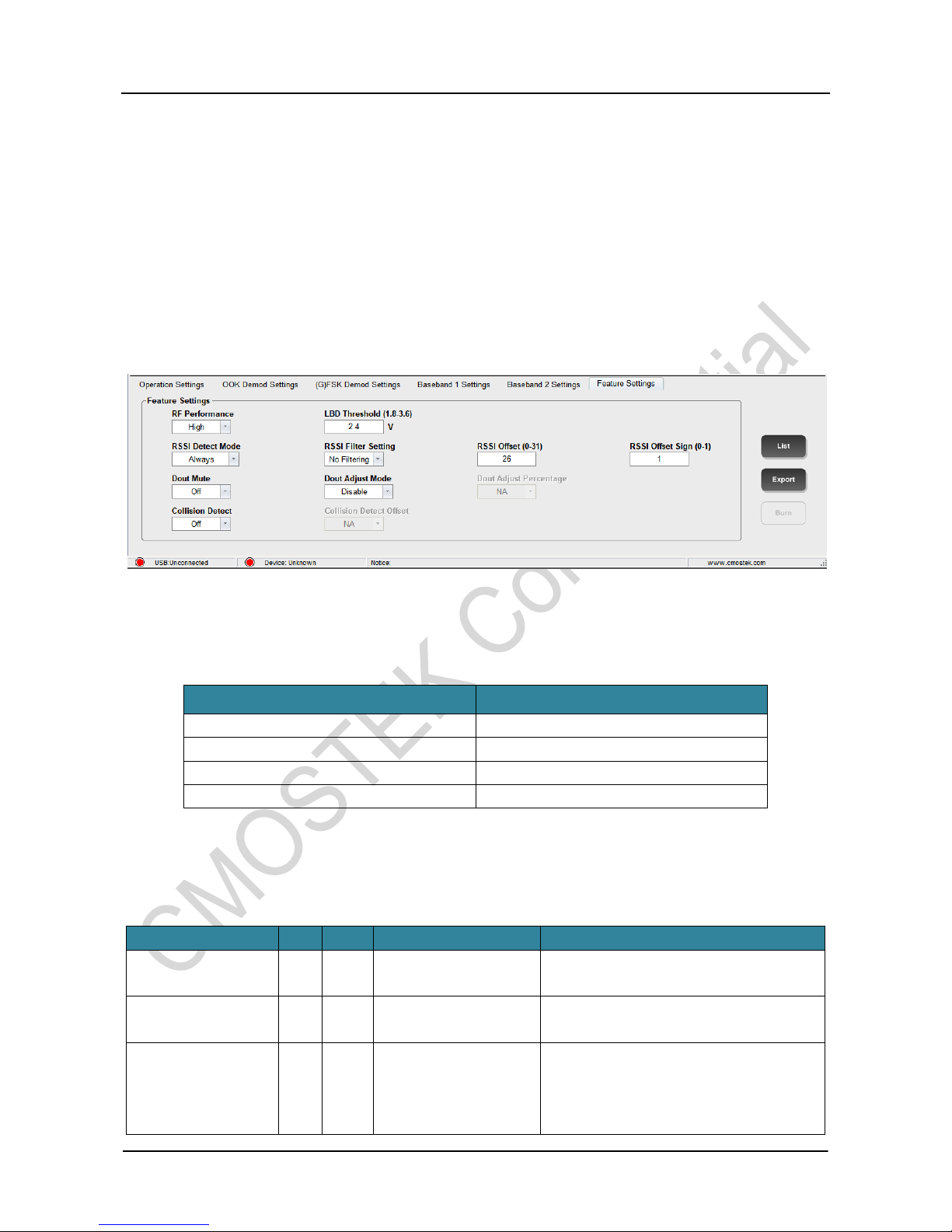
The corresponding RFPDK UI screen and parameters are shown in the below figure.
Figure 1. RFPDK UI Screen and Parameters for RSSI
Table 2. RSSI Related Bit Flags
Register Bit Flag for RFPDK
Register Bits
RSSI offset sign
RSSI_OFFSET_SIGN
RSSI offset
RSSI_OFFSET<4:0>
RSSI detection mode
RSSI_DET_SEL<1:0>
RSSI filter setting
RSSI_AVG_MODE<2:0>
See the below table for the register descriptions.
Table 3. Registers in Configuration Area
Name
Bits
R/W
Bit Flag
Description
CUS_CMT9 (0x08)
7
RW
RSSI_OFFSET_SIGN
The sign bit of the error compensation value for
RSSI measurement.
CUS_RSSI (0x0B)
7:3
RW
RSSI_OFFSET<4:0>
Error compensation value for RSSI
measurement.
CUS_SYS11 (0x16)
4:3
RW
RSSI_DET_SEL<1:0>
RSSI measurement time.
0: measure continuously
1: measure when PREAM_OK is active
2: measure when SYNC_OK is active

AN166
Rev0.7 | 4/8
www.cmostek.com
Name
Bits
R/W
Bit Flag
Description
3: measure when PKT_OK is active
2:0
RW
RSSI_AVG_MODE<2:0>
Average filtering order of RSSI measurement.
0: no filtering
1: 4th-order
2: 8th-order
3: 16th -order
4: 32nd order
Table 4. Registers in Control Area 2
Name
Bits
R/W
Bit Flag
Description
CUS_RSSI_CODE (0x6F)
7:0
RW
RSSI_CODE<7:0>
The read value of RSSI is an 8-bit code
without unit, which is the filtering output of
the SAR ADC.
CUS_RSSI_DBM (0x70)
7:0
RW
RSSI_DBM<7:0>
The read value of RSSI subtracted 128, with
a unit of dBm, is equivalent to the signal
power value at the input end of the antenna,
which is the output value of the SAR ADC
after filtering and unit conversion to dBm.
1.2 RSSI Measurement and Comparison in FSK mode
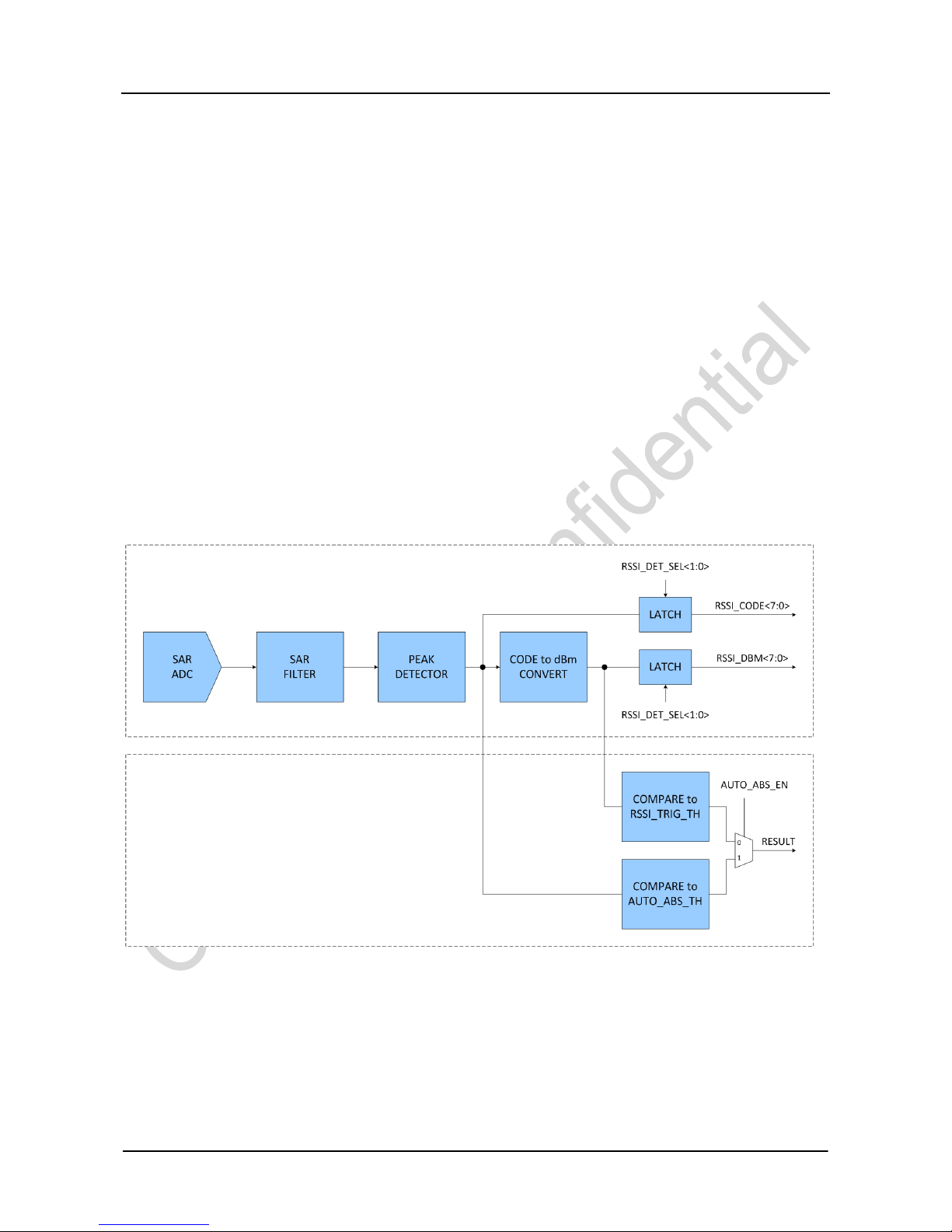
Figure 2. Structure Diagram of RSSI Measurement and Comparison in FSK mode
The RSSI measurement consists of following steps. First, through the SAR ADC, the real-time RSSI signal is converted to output
an 8-bit code value. Then first-order filtering is performed by SAR FILTER to obtain a relatively smooth RSSI code value. Then,
further smoothing is performed by the second-order RSSI AVG FILTER, with the order of the filtering set via
RSSI_AVG_MODE<2:0> by users. After the smoothing filtering, the code value is converted to a value in dBm. At last, the values
before and after the unit conversion are sent to the register for conditional latching with the latch condition configured by setting
RSSI Measurement
RSSI Comparison
AN166
Rev0.7 | 5/8
www.cmostek.com
RSSI_DET_SEL<1:0>. Users can read the register directly to obtain the final RSSI value.
In RSSI comparison procedure, the real-time RSSI value measured is compared to the threshold in dBm set by users in
RSSI_TRIG_TH<7:0>-128 and it outputs 1when it is greater than the threshold and outputs 0 when it is less. This output is used
as one of the RSSI_VLD signal sources.
The method of selecting smoothing filter order
The filtering order is equivalent to how many symbols passing through to obtained one correct RSSI value. The higher the order,
the longer the filtering time, and the more smooth the result is. However, the order is limited by the measurement condition as
well. For example, when RX_PREAM_SIZE is set as the length of 16 symbols, and RSSI_DET_SEL<1:0> is set to 1 (other words,
active PREAM_OK is set as the RSSI measurement condition), it can output a correct RSSI value only if the filtering order is set
not greater than 16. That is because, it receives PREAM_OK after receiving 16 symbols in a preamble, if the filtering order is set
as 16, it can exactly obtain one correct average value based on the 16 symbols received. Surely, a more stable measurement
result can be obtained if the order is set smaller than RX_PREAM_SIZE. Similarly, when the measurement condition is
SYNC_OK or PKT_OK, it needs to ensure the number of symbols received before the two interrupts occurring is greater than the
filtering order.
To accommodate different using habits of users, the CMT2219B provides both RSSI values in dBm and simple 8-bit code values.
RSSI values in dBm is recommended in general.
1.3 RSSI Measurement and Comparison in OOK Mode
Figure 3. Structure Diagram of RSSI Measurement and Comparison in OOK Mode
Since OOK is based on amplitude modulation, RSSI will show high and low transitions. However, users need a constant RSSI
value representing signal 1, therefore the PEAK DETECTOR is used in the circuit to pick up peak values (the RSSI value
representing 1) in the signal and output them to register.
Moreover, 2 RSSI comparison methods are available in OOK mode. One is the same as that of FSK mode, the other is called
automatic absolute threshold which is enabled by setting AUTO_ABS_EN. When it is enabled, the chip will generate a threshold
automatically for noise shielding and compared it to the output of PEAK DETECTOR with support of comparison result output.
RSSI Measurement
RSSI Comparison

AN166
Rev0.7 | 6/8
www.cmostek.com
The automatic absolute threshold has the advantage in automatic noise shielding, saying that, when there is no signal the
demodulation output is zero, with no noise impact. Moreover, the comparison results can also be used to help implement
super-low power (SLP) receiver, no need for users' manual measuring or debug to obtain appropriate thresholds. However, the
disadvantage is the loss of 12 dB of receiving sensitivity when automatic absolute threshold is used.
1.4 RSSI Measurement Result Compensation
The read value of RSSI_DBM minus 128 is the RSSI measurement result. Users can get the RSSI measurement result value this
way in general,
RSSI @ RF_Input = RSSI_dBm<7:0> -128
If a relatively high accurate measurement is required, it needs to perform further calibration after chip production or even after
chip being applied in user solutions.
These calibrations involve the use of the three registers mentioned above, RSSI_OFFSET<4:0>, RSSI_OFFSET_SIGN and
RSSI_CODE<7:0>. The calibration method is as follows: 1) let the chip enter the RX state with the configuration satisfying
application requirements. 2) set RSSI_OFFSET and RSSI_OFFSET_SIGN to 0. 3) add the sine wave RF signal with a in-band
signal strength of - 90 dBm to the RFIN end. 4) read the RSSI_CODE<7:0> value, calculate based on the following formula and
update the calculation result to the RSSI_OFFSET and RSSI_OFFSET_SIGN registers.
RSSI_OFFSET<4:0> = | RSSI_CODE<7:0> - 91|
RSSI_OFFSET_SIGN =
1, When RSSI_CODE<7:0> - 91 > 0
{0, When RSSI_CODE<7:0> - 91 < 0
After calibration, the RSSI measurement value is increasing monotonically from -128 dBm to 20 dBm. It shows fine linearity from
-100 to -50 dBm, reaching an accuracy of ±3dB.

AN166
Rev0.7 | 7/8
www.cmostek.com
2 Revise History
Table 2. Revise History Records
Version No.
Chapter
Description
Date
0.7
All
Initial version
2018-10-10
AN166
Rev0.7 | 8/8
www.cmostek.com
3 Contacts
CMOSTEK Microelectronics Co., Ltd. Shenzhen Branch
Address: 2/F Building 3, Pingshan Private Enterprise S.T. Park, Xili, Nanshan District, Shenzhen, Guangdong, China
Tel: +86-755-83231427
Post Code: 518057
Sales: sales@cmostek.com
Supports: sup[email protected]
Website: www.cmostek.com
The information furnished by CMOSTEK is believed to be accurate and reliable. However, no responsibility is assumed for
inaccuracies and specifications within this document are subject to change without notice. The material contained herein is
the exclusive property of CMOSTEK and shall not be distributed, reproduced, or disclosed in whole or in part without prior
written permission of CMOSTEK. CMOSTEK products are not authorized for use as critical components in life support
devices or systems without express written approval of CMOSTEK. The CMOSTEK logo is a registered trademark of
CMOSTEK Microelectronics Co., Ltd. All other names are the property of their respective owners.
Copyright. CMOSTEK Microelectronics Co., Ltd. All rights are reserved.
Other manuals for CMT2219B
1
Table of contents
Other CMOSTEK Receiver manuals


