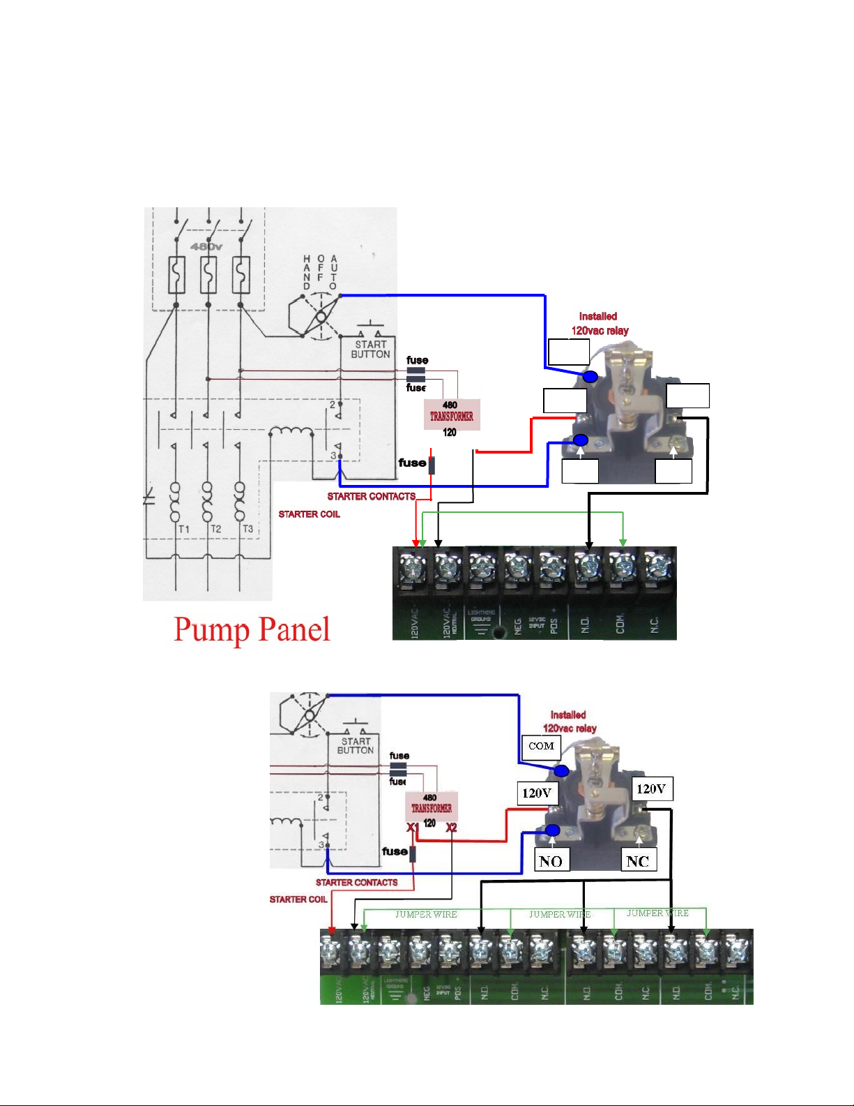
Hot Shot 810-R Plus User manual

IRRIGATION
810-R PLUS
RECEIVER GUIDE
Pg.
2 HOT SHOT OVERVIEW
3 RECEIVER INDICATOR LEDS
4 FUNCTION SWITCH SETTINGS
4 SUPERVISION FEATURE
4 SUPERVISION FAIL SAFE FEATURE
4 ENGINE STARTUP MODE
4 LOAD SHARING FEATURE
5 MULTIPLE RELAY OUTPUT CONTROL
6 RECEIVER HOOKUP TO ELECTRIC WELL
7 RECEIVER HOOKUP TO ELECTRIC WELL DIAGRAM
8 RECEIVER HOOKUP TO ENGINE DRIVEN WELL
Version : 1006
Hot Shot Systems Inc. will no longer sell or warranty its products for the use in controlling or monitoring pollut-
ants. However, the use of these controllers in non pollutant applications such as water tanks, water pumps, pivots,
irrigation systems and any other monitoring or control applications that do not involve pollutants are suitable for
these products.

2
ATTENTION: Depending upon the style of system that your are going to control with
the Hot Shot Wireless Controller you may need to supply additional parts. Such as relays,
step-down transformers, Murphy switches etc. These items are suggested in the wiring
guides that follow in this manual.
NOTE: This equipment has been tested and found to comply with the limits for a Class B
digital device, pursuant to part 15 of the FCC Rules. These limits are designed to provide
reasonable protection against harmful interference in a residential installation. This
equipment generates, uses and can radiate radio frequency energy and, if not installed
and used in accordance with the instructions, may cause harmful interference to radio
communications. However, there is no guarantee that interference will not occur in a par-
ticular installation. If this equipment does cause harmful interference to radio or televi-
sion reception, which can be determined by turning the equipment off and on, the user is
encouraged to try to correct the interference by one or more of the following measures:
Reorient or relocate the receiving antenna.
Increase the separation between the equipment and receiver.
Connect the equipment into an outlet on a circuit different from that to which the
receiver is connected.
Consult the dealer or an experienced radio/TV technician for help.
15.21 INFORMATION to USER:
The users manual or instruction manual for an intentional or unintentional radiator shall
caution the user that changes or modifications not expressly approved by the party re-
sponsible for compliance could void the user’s authority to operate the equipment.
HOW IT WORKS
Think of the HOT SHOT system as a control wire going from the transmitter site to the receiver
site. When the Hot Shot Transmitter’s SENSOR ON-OFF Input is connected to COM, a 10
second delay timer is started. After the delay timer has expired, the transmitter will send the
(Relay ON) command to the receiver. This will close the relay contacts between N.O. and
COM. When the SENSOR ON-OFF input at the transmitter is opened it will send the (Relay
OFF) command to the receiver switching the relay back to N.C. connected to COM. Battery
backup in the transmitter will still allow the HOT SHOT to work in case of power outage. Each
system is coded with its own four digit code so it will not interfere with other systems in the
same area. The following manual has been prepared to provide details for Transmitter installa-
tion and Receiver installation.
FCC License is not required. This device operates on frequencies authorized for
use in the Multi-Use Radio Service (MURS). MURS frequencies are available for unli-
censed business or personal use. Any changes or modifications may void the user’s au-
thority granted by the FCC to operate this radio and should not be made. Use of this ra-
dio outside the country where it was intended to be distributed is subject to government
regulations and may be prohibited.
ATTENTION: All Hot Shot units have a designated GROUND Terminal. Hot Shot units must have
there ground terminal connected to a proper ground or grounding system as per the NEC (National Electri-
cal Code) and or your local and state electrical code guidelines.

3
MOUNTING
Cabinets are a weatherproof UV protected NEMA 4X cabinet with mounting ears on top and
bottom. The cabinet can be mounted on the side of a control panel, pole or any other surface as
long as the antenna does not have metal running within 12” of the antenna whip. If longer range
is needed, an external long range antenna can be used. Do not mount the HOT SHOT receiver
to the well engine or cover because the strong vibrations can be harmful to the unit.
CODE SWITCH SETTINGS
All transmitters and receivers will be shipped from the factory with preprogrammed field codes. This ensures
that your neighbor will not duplicate the same field code as your unit. Your field codes already match, so you do
not need to program any codes. If you ever need to replace a unit due to servicing, the field code can be pro-
grammed to match the existing or new add on units. FOLLOW THE EXAMPLE BELOW…
FOR CODE QUESTIONS? CALL 785-623-1500
8 9
7
EXAMPLE: CODE 6789
KEY
7
8 9
0
5
63
4
6
OFF ON
Use the # KEY to the left
to make each digit of the
code. It takes three of the
switches to make one num-
ber of the code.
Use switches 1,2,3 for the
first # in the code. Switches
4,5,6 for the second #.
Switches 7,8,9 for the third
#. Switches 10,11,12 for the
fourth #.
Transmitter Code
Switches
INDICATOR LEDS
POWER Signals that the Receiver has power and is ready to receive the code from the Transmitter.
STROBE Used for troubleshooting, this LED flashes once for each of the four correct digits of the code
received. The LED will stay on steady for one second if an incorrect digit of the code is received.
Example: If the LED flashes two times and then goes on steady it is indicating that the third digit
doesn’t match. If the LED flashes one time and goes on steady it is indicating that the second
digit doesn’t match. If the LED comes on steady right away it is indicating that the first digit
doesn’t match.
RELAY When this LED is on it indicates that its corresponding relay has been activated.
SUPERVISION When this LED is flashing it indicates that it has not received its correct code from the
transmitter in the past 3hrs. Sliding function switch #8 to its OFF position will turn off this
indicator LED.

4
ENGINE STARTUP MODE
With function switch 6 on turn on the power to the receiver to enable the Engine Startup Mode. When activated the Supervi-
sion LED will come on and bypass the Murphy switch to allow the engine to start and stay running until the transmitter has sent
its relay ON command to the receiver thus ending the bypass timer and taking control of the receiver and turning off the Super-
vision LED. If the transmitter has not sent the relay ON command within 15 min the receiver will kill the engine and you will
have to turn the receiver off and then back on again to get it into Engine Startup Mode again.
SUPERVISION FEATURE
The Supervision Feature is a great way for checking at a glance the integrity of communications between the transmitter and
receivers. The supervision feature is designed to work with only one transmitter per system as the supervision feature’s timer
can operate on multiple receivers at the same time. When function 9 (Refresh) is turned on in the transmitter, it will send out a
check-in signal (technically it’s a command telling each receiver on the system to reset it’s supervision timer, i.e. system is
working properly) every 45 minutes. If the check-in signal is not heard by the receiver before the internal supervision timer
expires, due to transmitter or receiver issues, the receiver will then look at its function switches (7, 8 or 9) and take the selected
course of supervision action. See below.
FAIL-SAFE OPERATION
RELAY 1 OUTPUT ONLY
This feature works with the Supervision
feature as described above but lets us
take safety a step further. Fail-Safe
mode allows the receiver to control the
#1 internal relay by activating or deacti-
vating itself if the transmitter is not
working properly.
SCENARIO 1
Turning on Function switch 7 will
make the receiver’s internal #1 relay
energize if there is a system failure
(closing N.O. to COM.).
SCENARIO 2
Turning on Function Switch 9 will
make the receiver’s internal #1 relay de-
energize if there is a system failure
(closing N.C. to COM.).
LOAD SHARING
Different delay times on the receivers
can help with large electrical current
pulls in the same field on start up.
SWITCH# FUNCTION SWITCH SETTINGS
FOR RELAY #1 OUTPUT ONLY
1 ON WILL ACTIVATE MOMENTARY FOR 10 SEC.
2 ON INVERTED RELAY OUTPUT CONTROL
3 ON ACTIVATION OF RELAY DELAYED BY 10 SEC. (See Load Sharing below)
4ON ACTIVATION OF RELAY DELAYED BY 5 SEC. (See Load Sharing below)
5 NOT USED
6ON ACTIVATES ENIGNE STARTUP MODE - WITH 15MIN BY-PASS TIMER (See below)
7ON ACTIVATES FAIL-SAFE MODE - SCENERIO 1 (See FAIL-SAFE OPERTAION below)
8 ON ACTIVATES THE SUPERVISION MODE - LED ONLY.
9 ON ACTIVATES FAIL-SAFE MODE - SCENERIO 2 (See FAIL-SAFE OPERTAION below)

5
BASIC MULTIPLE PUMP OR RELAY CONTROL WIRING DIAGRAM
USING 1 HOT SHOT 810-R PLUS TO CONTROL UP TO 6 PUMPS OR RELAYS.
This style of receiver is convenient when the pumps or relays are located close together or when their power sup-
ply comes from the same circuit box. This will save money and time in eliminating the need for extra receivers at
each relay. See diagram below.
JUMPER WIRE
WELL #1 WELL #2 WELL #3
USING THE MULTIPLE RELAY OUTPUT TERMINALS
When a Hot Shot Receiver 810-R PLUS is going to be used with a
Hot Shot 810-T transmitter using it’s #1,2,3,4,5, OR 6 SENSOR
INPUT or the Pump Selector Kit the receiver’s going to be used will
need to use the corresponding transmitter SENSOR INPUT termi-
nals to control the pump or relay outputs accordingly. The #1 Sen-
sor Input on the transmitter will only turn ON and OFF the #1 Relay
Terminals on the receiver. The same goes for the #2 Sensor Input on
the transmitter will only turn ON and OFF the #2 Relay Terminals
on the receiver and so on for all the sensor inputs and corresponding
relay outputs. The picture shows the layout of the Relay Terminals
on the 810-R PLUS receiver.
#1
RELAY
#2
RELAY
#3
RELAY
#6
RELAY
#5
RELAY
#4
RELAY
JUMPER WIRE
WELL #4 WELL #5 WELL #6

6
ELECTRIC WELL HOOKUP
Mount a 480v-120v step-down transformer to supply 120v to the receiver. The Hot Shot Re-
ceiver only requires 1 watt of power to operate. Hot Shot Systems suggest using a minimum of
a single phase 60 hertz 0.050kVA transformer. They are available for purchase through Hot
Shot Systems, just request when ordering.
Mount a 3 terminal fuse block and a 120vac relay. Hot Shot Systems suggest using a 115V AC
coil relay. They are available for purchase through Hot Shot Systems, just request when or-
dering.
Wire two, 480v conductors through the first two fuses (1/2 or 1 amp each) to the primary side
of the step-down transformer. Terminals may be different according to the transformer
installed.
Wire the 120v X1 terminal of the step-down transformer through the remaining fuse (1 amp)
which then goes to the first 120vac input of the Hot Shot Receiver (120 volt polarity does not
matter).
Wire the 120v X2 terminal of the step-down transformer to the neutral 120vac input of the Hot
Shot Receiver (see diagram on the next page).
Add a jumper from the first 120vac terminal to the Hot Shot Receivers relay COM. terminal
(see diagram on the next page).
Wire the NO. terminal on the Hot Shot Receiver to one side of the 120v relay coil.
Connect the other side of the relay coil to the X2 terminal of the step-down transformer.
Connect a wire from the Ground terminal of the Hot Shot Receiver to a central grounding
system (ground rod).
CAUTION: Never switch any voltage greater than 120v with the Hot Shot Receivers internal
relays. This will ruin the relay and void all manufacturer warranties. Use an externally
mounted 120v coil relay to switch all voltages greater than 120v. This will be shown later in
Electric Well Hookup section.
HOT SHOT RECEIVERS NEED TO BE TURNED ON BEFORE THE HOT SHOT TRANSMITTERS
ARE TURNED ON. HOT SHOT TRANSMITTERS ONLY TRANSMITT FOR 1 MINUTE. IF THE RE-
CEIVER IS TURNED ON AFTER THE TRANSMITTER IT WILL NOT OPERATE CORRECTLY UN-
TIL THE TRANSMITTER IS SET TO TRANSMITT AGAIN.

7
Relay
Coil
NCNO
120V 120V
COM
JUMPER WIRE
ELECTRIC WELL HOOKUP DIAGRAM
OBJECT: WHEN THE HOT SHOT TRANSMITTER’S RELAY INPUT TO COMMON IS CLOSED IT
SENDS OUT THE RELAY ON COMMAND TO THE RECEIVER. WHEN THE HOT SHOT
RECEIVER GETS THE ON SIGNAL IT WILL CLOSE ITS N.O. TO COMMON CONTACTS.
THIS WILL ENERGIZE THE 120V RELAY TO CLOSE THE 480V CONTACTOR.
ELECTRIC WELL HOOKUP DIAGRAM W/ 3 RELAYS IN PARALLEL
This diagram illustrates
how to let an electric
pump stay operating
until all the transmitters
have sent their turn off
command. It is a sim-
ple way of wiring all
the receiver relays in
parallel so that the
pump stays operating
until all the relays have
opened.
X1
X2

8
TYPICAL HOT SHOT RECEIVER HOOKUP TO SHUTDOWN
A ENGINE DRIVEN WELL
HOT SHOT RECEIVERS NEED TO BE TURNED ON BEFORE THE HOT SHOT TRANSMITTERS
ARE TURNED ON. HOT SHOT TRANSMITTER ONLY TRANSMITT FOR 1 MINUTE. IF THE RE-
CEIVER IS TURNED ON AFTER THE TRANSMITTER IT WILL NOT OPERATE CORRECTLY
UNTIL THE TRANSMITTER IS SET TO TRANSMITT AGAIN.
AT THE ENGINE
DO NOT mount the HOT SHOT Receiver unit to the well engine or engine cover because strong vibra-
tions can be harmful to the unit.
The diagrams below show a simple way to control an engine driven well using a simple 117 or 518 Murphy kill
switch. Supply power to the receiver by hooking up the 12v positive input on the receiver to the 12v positive
terminal on the battery. Run a wire from the Negative input on the receiver to the negative terminal on the bat-
tery or to a good ground connection. Install a jumper wire connecting the negative terminal to the COM terminal
on the receiver. Connect a wire from the N.C. terminal on the Hot Shot receiver to the S or the SW1 terminal on
the Murphy kill switch. Turn on function switch 6 and turn on the power to the receiver to enable the Engine
Startup Mode (for details see pg 4). When activated the Supervision LED will come on and bypass the Murphy
switch to allow the engine to start and stay running until the transmitter has sent its relay ON command to the
receiver thus ending the bypass timer and taking control of the receiver and turning off the Supervision LED. If
the transmitter has not sent the relay ON command within 15 min the receiver will kill the engine and you will
have to turn the receiver off and then back on again to get it into Engine Startup Mode again. Now when the
pivot is finished or the safety is tripped the receiver will be sent a stop water signal, the receiver’s relay will
close COM to NC. This shorts the Sterminal to ground and kills the engine. Other variations and Murphy Kill
switches will work as well.
Engine Driven Well Hookup Diagrams
JUMPER WIRE
BATTERY
+ -
COIL
DISTR.
BATTERY
+ -
COIL
DISTR.
117 518
JUMPER WIRE
MURPHY 117 SWITCH MURPHY 518 SWITCH

9
HOT SHOT GROUNDING
FOR SAFETY AND PEAK PERFORMANCE
Hot Shot wireless systems are equipped with a GROUND terminal that
needs to be connected to an NEC approved ground rod. A Hot Shot has
various lightning and static protection devices incorporated on the cir-
cuit board that require proper grounding to operate. Any equipment or
device panels operating with or near the Hot Shot should also be con-
nected to the grounding system. A good ground will enhance the trans-
mit and receive range of the Hot Shot System.
GROUNDING
PER NATIONAL
ELECTRICAL CODE
DEVICE
PANEL

10
APPENDIX
SUPERVISION FEATURE
The Supervision Feature is a great way for checking at a glance the integrity of communications between the trans-
mitter and receivers. The supervision feature is designed to work with only one transmitter per system as the su-
pervision feature’s timer can operate on multiple receivers at the same time. When function 9 (Refresh) is turned
on in the transmitter, it will send out a check-in signal (technically it’s a command telling each receiver on the
system to reset it’s supervision timer, i.e. system is working properly) every 45 minutes. If the check-in signal is
not heard by the receiver before the internal supervision timer expires, due to transmitter or receiver issues, the
receiver will then look at its function switches (7, 8 or 9) and take the selected course of supervision action. See
below.
Receiver’s Supervision/Fail Safe action:
If Function 8 is on in the receiver and the supervision timer does not get reset by the transmitter’s check-
in signal the supervision LED will begin to blink continuously. No action will be performed by the receivers re-
lay. The supervision LED will continue to blink until either the receiver receives the transmitter’s check-in signal
or the receiver is reset by pressing the reset button, if equipped, or by cycling the power to the receiver.
If Function 7 (Fail Safe Scenario 1) is on in the receiver and the supervision timer does not get reset by
the transmitter’s check-in signal the supervision LED will begin to blink continuously. This will also activate the
receivers relay which will close or open your contacts, (N.C. / N.O.) possibly triggering an alarm, call out system,
deactivate an external relays coil or trip a tattletale circuit to stop the device it is controlling. The supervision LED
will continue to blink and the receivers relay will stay activated until either the receiver receives the transmitter’s
check-in signal, a relay reset command from the transmitter or the receiver is reset by pressing the reset button, if
equipped, or by cycling or losing power to the receiver.
Operational Note: When using Fail Safe Scenario 1, the receiver’s relay is energized and if power is lost
while the receiver is in Fail Safe operation, the receiver’s relay will de-energize. When power is restored, the re-
ceivers relay will not immediately go back into Fail Safe operation. The receivers relay will remain de-energized
and the device it is controlling may restart. The receiver will not go into Fail Safe operation again until it’s super-
vision timer has expired again. If this situation occurs, a tattletale device that does not recycle when the power
comes back on, should be installed to hold the circuit as needed for your situation.
If Function 9 (Fail Safe Scenario 2) is on in the receiver and the supervision timer does not get reset by
the transmitter’s check-in signal the supervision LED will begin to blink continuously. This will also deactivate
the receiver’s relay, if currently activated, which will close or open your contacts, (N.C. / N.O.) possibly trigger-
ing an alarm, call out system, deactivate any external relays coil or trip a tattletale circuit to stop the device it is
controlling. The supervision LED will continue to blink until either the receiver receives the transmitter’s check-
in signal or a relay ON or OFF command from the transmitter.
Transmitter Setting for Supervision/Fail Safe Operation at the Receiver:
Function 9 (Refresh - sends checking in signal every 45 min.)
This function must be turned on in the transmitter so the transmitter will send out the signal to make the receiver(s)
supervision timer reset. IF the transmitter does not have this function turned on the absence of the refresh/check in
signal will cause the reciver(s) to go into Supervision or a Fail Safe action.
Testing Supervision/Fail Safe Operation:
A good way to test the Supervision/ Fail Safe Operation is to turn off function switch 9 on the transmitter,
so it will no longer send the refresh/check-in signal. Once the receiver’s supervision timer has expired, (may take
up to 3 hrs depending on the version of software the receiver is operating) the Supervision LED will begin to blink
and depending upon the Fail Safe scenario you have chosen, the receivers relay will activate or de-active.
Table of contents
Other Hot Shot Receiver manuals