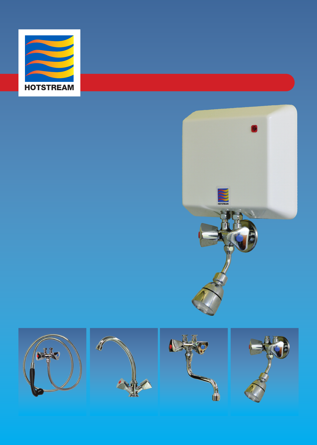
HOTSTREAM TAPWARE - OPEN VENTED HOTSTREAM Installation Instructions
1. ELECTRICAL REQUIREMENTS
• This appliance must be earthed.
• Cold water resistivity rating 1300 Ohm.cm at 15°C.
• This appliance must be wired and connected by a registered
electrician in accordance with local wiring regulations.
WARNING: A supply isolation switch MUST be tted.
• Electrician to check for cable size to prevent voltage drop.
• Using the hot tap, air must be bled from heater before electrical
power is switched on.
•This is an open outlet appliance. Pressure rating 0 pa.
ONLY HOTSTREAM TAPS AND FITTINGS MUST BE USED
2. PLUMBING REQUIREMENTS
1. Minimum water pressure: 240 kPa (35psi)
Maximum water pressure: 517 kPa (72psi)
2. All units must be installed by a registered Plumber.
3. The Hotstream heater is an open outlet appliance. The
outlet acts as a vent and must always remain open to the
atmosphere. For this reason, only Hotstream taps and
fittings must be used.
4. All air must be bled from heater and pipes by turning
on the hot tap and letting run for 5 minutes BEFORE
the electricity is switched on. This procedure must be
followed whenever the water supply is interrupted, turned
off or whenever there is a risk of air pockets being present
in the water supply. In areas prone to air locks in the water
supply, an air eliminator valve should be fitted.
5. In New Zealand: an insolating stop-cock must be fitted
to the cold water supply for all models.
6. Take care during installation of heaters. Unnecessary force
can result in breakage.
7. For multiple installations where all units are likely to be
in operation at the same time (e.g. bank of showers,
washrooms, hairdressing salons etc) it is CRITICAL that
the plumbing allows for sufcient water ow, regardless
of pressure. In general, the diameter of the cold water
pipe must increase proportionately as the number of units
increases, in order to compensate for pressure drops when
all units are operating. As an example, for a bank of 8 units,
a 1½” feed pipe would generally be required rather than a
½” pipe, depending upon pressure.
8. We recommend tting a 350 kPa pressure limiting valve
to all installations where the incoming pressure exceeds
500 kPa.
WARNING: Water heater must not be switched on if there is a possibility that the water in the heater is frozen.
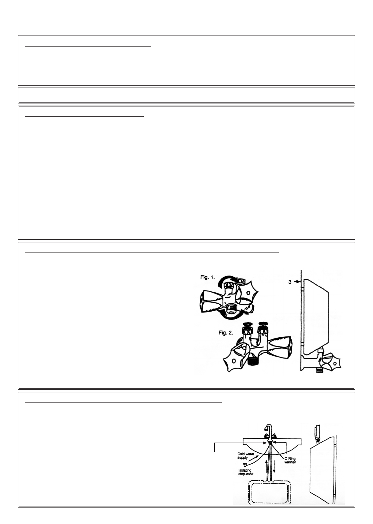
3. FOR HEATERS INSTALLED ABOVE THE BASIN OR IN SHOWERS
1. For new installations one ½”/15mm BSP female threaded
cold water supply socket is required.
2. Screw the mixing tap into the water main nishing in a
horizontal position as illustrated in Fig. 1.
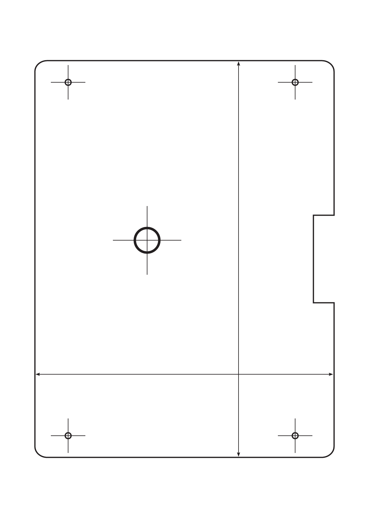
3. Temporarily mount heater unit minus front cover. Ensure
distance of mixing tap from wall surface is compatible
with distance required to attach the unit directly a at wall
surface. If this is not possible - see attachment.
4. Place the supplied washer in to each connecting nut and
mount the heater into position. When tightening hexagonal
nuts on mixer do not apply excessive force.
5. Turn on the water mains supply.
6. Bleed all air from heater and pipes by turning on
the HOT tap and let run for 5 minutes BEFORE the
electricity is switched on.
7. A packer may be necessary to allow the unit to be screwed
back with even pressure, with no excess pressure on the
heater unit (NB: excess pressure on the back mounting
cover will cause the unit to leak.
4. FOR HEATERS INSTALLED BENEATH THE BASIN
1. Fix the three-way combination tap securely to the hand
basin or kitchen bench, ensuring that the sealing washers
supplied are tted correctly.
2. Turn off the water mains supply and close both taps of the
mixer.
3. Connect the short pipe to the cold water mains control tap.
4. Connect the long pipe (with the blue arrow pointing
downwards) to the inlet side of the heater as shown by
the arrow on the heater. (This is the cold water supply to
the heater).
5. Connect the pipe with the red arrow to the outlet of the
heater. Do not forget the washers.
6. Turn on the water mains supply.
7. Bleed all air from the heater and pipes by turning
on HOT tap and let run for 5 minutes BEFORE the
electricity is switched on.
Hot inlet
Cold inlet
O Ring
Right to left