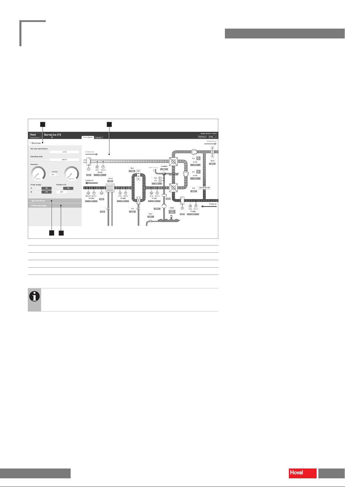
3.2 Specifications
BMS/Local set value specications
Displaying the set value specications for BMS operation, displaying and setting
the set value specications for local operation:
– Temperature (supply air)
– Humidity (supply air)
– Flowrate (supply air)
– Enabling (unit)
■In each case, click on the icon.
■Enter the desired value.
■Click the icon to save the value.
CPS
Dene the target temperature for the Condensation Prevention System to prevent
condensation of moisture in the recirculation air ow:
– Temperature (fresh air after admixture of exhaust air)
Time program Winter operation
Dene the period in which the unit runs in the 'Winter' operating mode.
■In each case, click on the icon.
■Enter the on and o dates for winter operation.
■Click the icon to save the value.
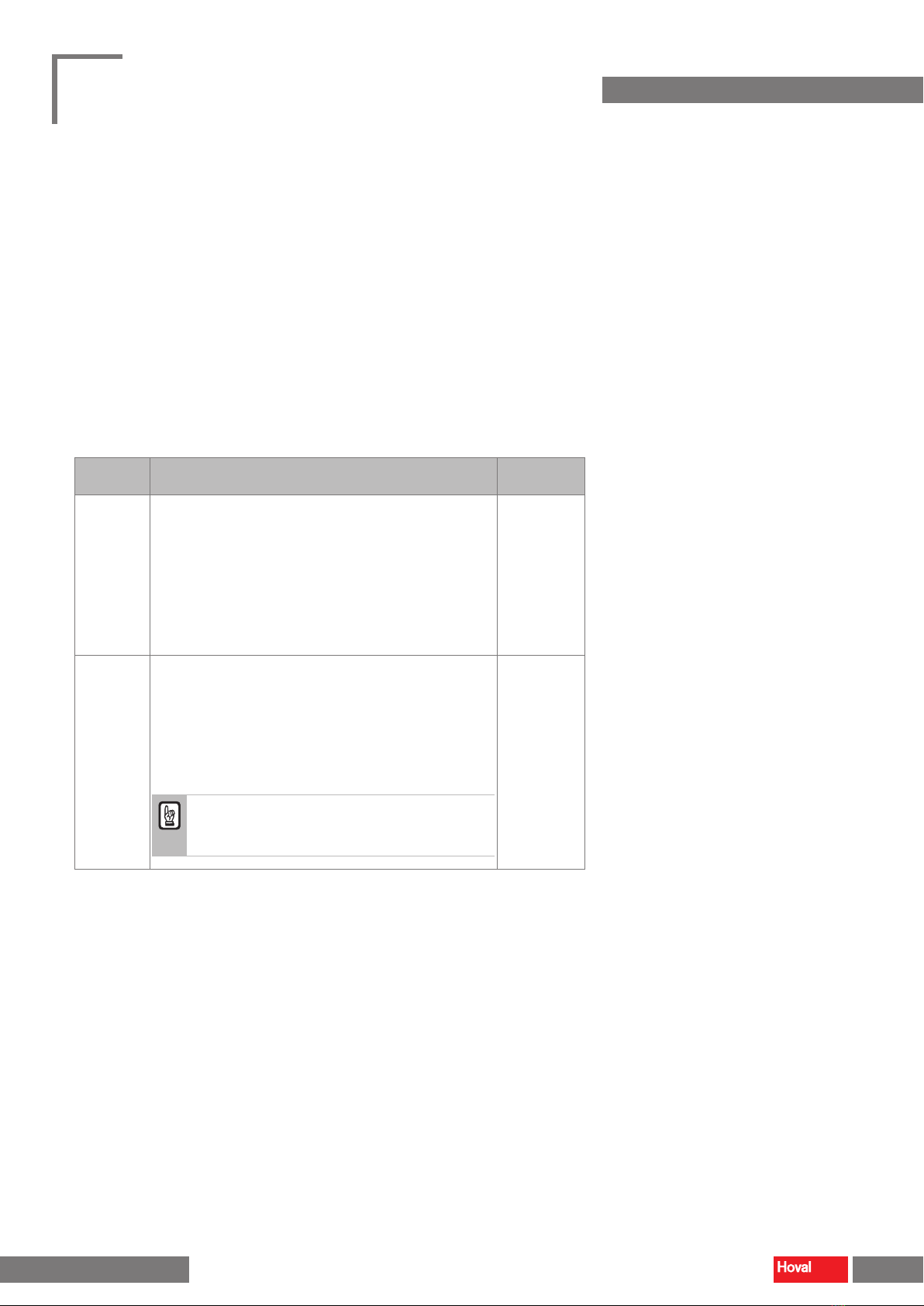
Attention
When switching to winter operation, ensure that the adiabatic system is
drained and frost-proofed.
3.3 Fault messages
The list of fault messages shows all faults with date and time of their occurrence:
– Active faults appear in red.
– Corrected faults appear in green.
■Click on 'Reset' to acknowledge faults.
Notice
The list of past faults is successively loaded by the unit controller.
For data that is further back in time, the loading times may be longer.
9
System control for ServeCool Process diagram
4 219 126-en-01