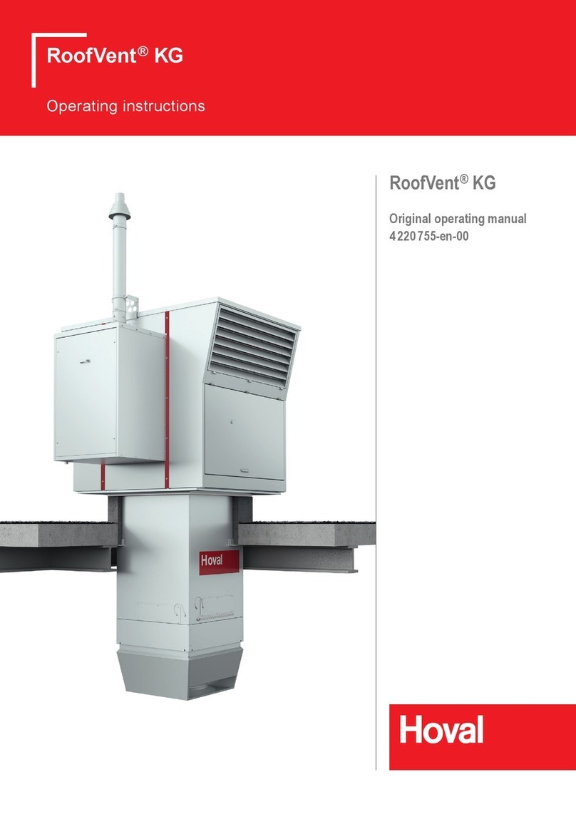
Hoval RoofVent RH Series Installation instructions

RoofVent®RH |RC |RHC |R
Art.No. 4 214 745-en-04 / Page 1
RoofVent®RH
RoofVent®RC
RoofVent®RHC
RoofVent®R
Original operating manual

1 Use 3
1.1 Intended use 3
1.2 User group 3
2 Safety 4
2.1 Symbols 4
2.2 Operational safety 4
3 Construction and operation 5
3.1 Construction 5
3.2 Air distribution with the Air-Injector 5
3.3 Function diagram 7
3.4 Operating modes 8
4 Unit type reference 10
5 Technical data 12
5.1 Application limits 12
5.2 Heat recovery system (HRS) 12
5.3 Air ltration 12
5.4 Flow rate, product parameters 13
5.5 Heat output 14
5.6 Cooling capacities 15
5.7 Dimensions and weights of the RoofVent® RH 16
5.8 Dimensions and weights of the RoofVent® RC 18
5.9 Dimensions and weights of the RoofVent® RHC 20
5.10 Dimensions and weights of the RoofVent® R 22
6 Options 24
6.1 Oil-proof design 24
6.2 Design for high extract air humidity 24
6.3 Corrosion-protected design 24
6.4 Corrosion-protected design
for high extract air humidity 24
6.5 Connection module 25
6.6 Design with 2 Air-Injectors 25
6.7 Design without Air-Injector 25
6.8 Paint nish of below-roof unit 25
6.9 Fresh air silencer 26
6.10 Exhaust air silencer 26
6.11 Supply air and extract air silencers 27
6.12 Hydraulic assembly diverting system 27
6.13 Mixing valve 27
6.14 Condensate pump 27
6.15 Socket 28
6.16 Energy monitoring 28
6.17 Return temperature sensor 28
6.18 Pump control for mixing or injection system 28
7 Transport and installation 29
7.1 Delivery 29
7.2 Requirements for the installation site 31
7.3 Installation 32
7.4 Connecting air ducts and Air-Injectors 38
7.5 Hydraulic installation 39
7.6 Condensate connection 40
7.7 Electrical installation 42
8 Operation 43
8.1 Initial commissioning 43
8.2 Operation 43
9 Maintenance and repair 44
9.1 Safety 44
9.2 Maintenance 45
9.3 Repair 47
10 Dismantling 47
11 Disposal 47
RoofVent®RH |RC |RHC |R
Art.No. 4 214 745-en-04 / Page 2

1 Use
1.1 Intended use
RoofVent® units are supply and extract air handling units for use in tall, single-oor
halls. They have the following functions:
■ Fresh air supply
■ Extract air removal
■ Energy recovery with highly efcient plate heat exchanger
■ Filtering of the fresh air and the extract air
■ Air distribution with adjustable Air-Injector
Additional functions depending on unit type:
■ Heating (with connection to a hot water supply)
■ Cooling (with connection to a water chiller)
A system usually consists of several RoofVent® units. These are installed distrib-
uted throughout the hall roof. The individual units are regulated individually and
controlled based on zones. The system exibly adjusts to local requirements.
RoofVent® units comply with all the requirements of the Ecodesign Directive
relating to environmentally friendly design of ventilation systems. They are
systems of the 'non-residential ventilation unit' (NRVU) and 'bidirectional ventila-
tion unit' (BVU) type.
Intended use also includes compliance with the operating instructions. Any usage
over and above this use is considered to be not as intended. The manufacturer
can accept no liability for damage resulting from improper use.
1.2 User group
The units are only allowed to be installed, operated and maintained by authorised
and instructed personnel who are well acquainted with the units and are informed
about possible dangers.
The operating instructions are for operating engineers and technicians as well as
specialists in building, heating and ventilation technology.
RoofVent®RH |RC |RHC |R
Use
Art.No. 4 214 745-en-04 / Page 3

2 Safety
2.1 Symbols
Caution
This symbol warns against risk of injury. Please heed all instructions desig-
nated by this symbol to prevent injuries and/or death.
Attention
This symbol warns against property damage. Please heed the respective
instructions to prevent risk of damage to the unit and its functions.
Notice
This symbol denotes information about the economic use of the equipment
or special tips.
2.2 Operational safety
The unit is built to conform to the state-of-the-art and is operationally safe. Despite
every precaution being taken, potential and not immediately obvious risks always
remain, for example:
■ Dangers when working with the electrical system
■ Parts (e.g. tools) can fall down below when working on the ventilation unit.
■ Dangers from working on the roof
■ Damage to devices or components due to lightning
■ Malfunctions as a result of defective parts
■ Hazards from hot water when working on the hot water supply
■ Water penetration through the roof unit if the access panels are not closed
correctly
Therefore:
■ Please read the operating instructions before unpacking, installing, commis-
sioning and before maintaining the equipment.
■ Store the operating instructions so that they are easily accessible.
■ Observe any attached information and warning signs.
■ Immediately replace damaged or removed informational and warning signs.
■ Follow the local safety and accident prevention regulations at all times.
■ When working in the unit, take precautions against unprotected, sharp metal
edges.
■ The unit may only be installed, operated and serviced by authorised, trained
and instructed skilled personnel:
– Specialists as dened by these operating instructions are those persons
who, based on their training, knowledge and experience as well as their
knowledge of the relevant regulations and guidelines, can carry out the work
assigned to them and recognise potential hazards.
■ Unauthorised reconguration or modication of the unit is not permitted.
RoofVent®RH |RC |RHC |R
Safety
Art.No. 4 214 745-en-04 / Page 4

3 Construction and operation
3.1 Construction
RoofVent® units consist of the following components:
■ Roof unit with energy recovery
■ Below-roof unit
The components are bolted together and can be dismantled. The connections of
the coil are located under the extract air grille as standard. The heating/cooling
section can also be mounted on the connection module turned round.
3.2 Air distribution with the Air-Injector
The patented air distributor – called the Air-Injector – is the core element. The air
discharge angle is set by means of the innitely variable guide vanes. It depends
on the air ow rate, the mounting height and the temperature difference between
the supply air and room air. The air is therefore blown into the room vertically
downward, conically or horizontally. This ensures that:
■ with each RoofVent® unit a large area of the hall can be reached,
■ the occupied area is draught-free,
■ the temperature stratication in the room is reduced, thus saving energy.
a
b
d
c
Roof unit with energy recovery
Below-roof unit
a Connection module
b Heating section (RoofVent® RH, RHC only)
c Cooling section (RoofVent® RC, RHC only)
d Air-Injector
Fig. 1: Components of RoofVent®units
RoofVent®RH |RC |RHC |R
Construction and operation
Art.No. 4 214 745-en-04 / Page 5

Condensate separator
(RoofVent® RC, RHC only)
Cooling coil
(RoofVent® RC, RHC only)
Heating coil
(RoofVent® RH, RHC only)
Access panel, coil
Access panel, connection box
Supply air fans
Supply air access door
Control block
Exhaust air access door
Exhaust air fans
Plate heat exchanger with bypass
(for performance control and as
recirculation bypass)
Fresh air damper with actuator
Bypass damper with actuator
Fresh air lter
Fresh air access door
Extract air and recirculation
dampers with actuator
Extract air access door
Extract air lter
Extract air grille
Frost controller
(RoofVent® RH, RC, RHC only)
Condensate connection
(RoofVent® RC, RHC only)
Actuator of the Air-Injector
Fig. 2: Structure of the RoofVent®units
RoofVent®RH |RC |RHC |R
Construction and operation
Art.No. 4 214 745-en-04 / Page 6

3.3 Function diagram
Fresh air
Fresh air lter with differential pressure switch
Temperature sensor air inlet ER (optional)
Bypass damper with actuator
Exhaust air temperature sensor
Exhaust air fans with ow rate monitoring
Exhaust air
Fresh air damper with actuator
Plate heat exchanger
Extract air temperature sensor
Extract air damper with actuator
Recirculation damper (opposed to the extract air
damper)
Temperature sensor air outlet ER (optional)
Extract air lter with differential pressure switch
Supply air fans with ow rate monitoring
Extract air
Heating coil (RoofVent® RH, RHC only)
Frost controller (RoofVent® RH, RC, RHC only)
Cooling coil (RoofVent® RC, RHC only)
Condensate separator (RoofVent® RC, RHC only)
Air-Injector with actuator
Supply air sensor
Supply air
Fig. 3: Function diagram
RoofVent®RH |RC |RHC |R
Construction and operation
Art.No. 4 214 745-en-04 / Page 7

3.4 Operating modes
The units have the following operating modes:
■ Ventilation
■ Ventilation (reduced)
■ Air quality
■ Recirculation (
depending on unit type
)
■ Exhaust air
■ Supply air
■ Standby
■ Forced heating
The TopTronic® C control system regulates these operating modes automatically
for each control zone in accordance with the specications in the calendar. The
following points also apply:
■ The operating mode of a control zone can be switched over manually.
■ Each RoofVent® unit can operate individually in a local operating mode: Off,
Recirculation, Supply air, Exhaust air, Ventilation.
Code Operating mode Description
VE Ventilation
The unit blows fresh air into the room and exhausts polluted room air. The
room temperature set value day is active. Depending on the temperature
conditions, the system continuously controls:
■ the energy recovery
■ the heating/cooling
Supply air fan................... on *)
Exhaust air fan................. on *)
Energy recovery............... 0-100 %
Extract air damper............ open
Recirculation damper ....... closed
Heating/cooling ................ 0-100 %
*) Adjustable ow rate
VEL Ventilation (reduced)
As VE, but the unit only operates with the set minimum values for the
supply and exhaust air volumes
Supply air fan................... MIN
Exhaust air fan................. MIN
Energy recovery............... 0-100 %
Extract air damper............ open
Recirculation damper ....... closed
Heating/cooling ................ 0-100 %
AQ Air quality
This is the operating mode for demand-controlled ventilation of the room.
The room temperature set value day is active. Depending on the tempera-
ture conditions, the system continuously controls:
■ the energy recovery
■ the heating/cooling
Depending on the room air quality, the system operates in one of the
following operating states:
AQ_REC
■Air quality Recirculation:
When air quality is good, the unit heats or cools in recirculation
operation.
Like REC
AQ_ECO
■Air quality Mixed air:
When ventilation requirements are medium, the unit heats or cools in
mixed air operation. The supply/exhaust air volume is based on the air
quality.
Supply air fan................... MIN-MAX
Exhaust air fan................. MIN-MAX
Energy recovery............... 0-100 %
Extract air damper............ 50 %
Recirculation damper ....... 50 %
Heating/cooling ................ 0-100 %
AQ_VE
■Air quality Ventilation:
When ventilation requirements are high, the unit heats or cools in pure
ventilation operation. The supply/exhaust air volume is based on the air
quality.
Supply air fan................... MIN-MAX
Exhaust air fan................. MIN-MAX
Energy recovery............... 0-100 %
Extract air damper............ open
Recirculation damper ....... closed
Heating/cooling ................ 0-100 %
RoofVent®RH |RC |RHC |R
Construction and operation
Art.No. 4 214 745-en-04 / Page 8

Code Operating mode Description
REC Recirculation
On/Off recirculation operation with TempTronic algorithm: During heat
or cool demand, the unit draws in room air, heats or cools it and blows it
back into the room. The room temperature set value day is active. The
ow rate is controlled in 2 stages.
Supply air fan................... 0 / Speed 1 / Speed 2 *)
Exhaust air fan................. off
Energy recovery............... 0 %
Extract air damper............ closed
Recirculation damper ....... open
Heating/cooling ................ on *)
*) Depending on heat or cool demand
EA Exhaust air
The unit extracts spent room air. There is no room temperature control.
Unltered fresh air enters the room through open windows and doors or
another system provides air supply.
Supply air fan................... Off
Exhaust air fan................. on *)
Energy recovery............... 0 %
Extract air damper............ open
Recirculation damper ....... closed
Heating/cooling ................ off
*) Adjustable ow rate
SA Supply air
The unit blows fresh air into the room. The room temperature set value
day is active. Depending on the temperature conditions, the system
controls the heating/cooling.
Spent room air passes through open windows and doors or another
system provides extraction.
Supply air fan................... on *)
Exhaust air fan................. off
Energy recovery............... 0 % **)
Extract air damper............ open
Recirculation damper ....... closed
Heating/cooling ................ 0-100 %
*) Adjustable ow rate
**) Fresh air and bypass dampers are open
ST Standby
The unit is normally switched off.
The following functions remain active:
CPR
■ Cooling protection:
If the room temperature drops below the set value for cooling protec-
tion, the unit heats up the room in recirculation operation.
Supply air fan................... MAX
Exhaust air fan................. off
Energy recovery............... 0 %
Extract air damper............ closed
Recirculation damper ....... open
Heating/cooling ................ on
OPR
■ Overheating protection:
If the room temperature rises above the set value for overheating
protection, the unit cools down the room in recirculation operation. If
the temperatures also permit fresh air cooling, the units automatically
switches to night cooling (NCS) to save energy.
NCS
■ Night cooling:
If the room temperature exceeds the set value for night cooling and
the current fresh air temperature permits it, the unit blows cool fresh air
into the room and extracts warmer room air.
Supply air fan................... on *)
Exhaust air fan................. on *)
Energy recovery............... 0 %
Extract air damper............ open
Recirculation damper ....... closed
Heating/cooling ................ off
*) Adjustable ow rate
L_OFF Off (local operating mode)
The unit is switched off. Frost protection remains active.
Supply air fan................... Off
Exhaust air fan................. off
Energy recovery............... 0 %
Extract air damper............ closed
Recirculation damper ....... open
Heating/cooling ................ off
– Forced heating
The unit draws in room air, warms it and blows it back into the room.
Forced heating is activated by inserting a wire jumper in the control
block. For example, it is suitable for heating the hall before taking the
control system into operation or if the controller fails during the heating
period. Connecting a room thermostat makes it possible to specify a room
temperature set value.
Supply air fan................... MAX
Exhaust air fan................. off
Energy recovery............... 0 %
Extract air damper............ closed
Recirculation damper ....... open
Heating ............................ on
Table 1: Operating modes of the RoofVent®units
RoofVent®RH |RC |RHC |R
Construction and operation
Art.No. 4 214 745-en-04 / Page 9

4 Unit type reference
RHC - 9 B C - RX / ST . -- / V0 . D1 . LU / AF . SI / Y . KP . -- . SD / TC . EM . PH . RF / S---
Unit type
RoofVent® RH | RC | RHC | R
Unit size
6 or 9
Heating section
- without heating section
B with coil type B
C with coil type C
D with coil type D
Heating/cooling section
- without heating/cooling section
C with coil type C
D with coil type D
Heat recovery
RX Temperature efciency ErP 2018
Design
ST Standard
OE Oil-proof design
HA Design for high extract air humidity
KG Corrosion-protected design
KA Corrosion-protected design for high extract air humidity
Reserve
Connection module
V0 Standard
V1 Length + 250 mm
V2 Length + 500 mm
V3 Length + 1000 mm
Air outlet
D1 Design with 1 Air-Injector
D2 Design with 2 Air-Injectors
D0 Design without Air-Injector
Paint nish
- without
LU Paint nish of below-roof unit
RoofVent®RH |RC |RHC |R
Unit type reference
Art.No. 4 214 745-en-04 / Page 10

RHC - 9 B C - RX / ST . -- / V0 . D1 . LU / AF . SI / Y . KP . -- . SD / TC . EM . PH . RF / S---
Silencers outside
- without
A- Fresh air silencer
-F Exhaust air silencer
AF Fresh air and exhaust air silencer
Silencers inside
- without
SI Supply air and extract air silencer
Hydraulics
- without
Y Hydraulic assembly diverting system
M Mixing valve
Condensate pump
- without
KP Condensate pump
Socket
- without
SD Socket in the unit
CH Socket in the unit Switzerland
Control system
TC TopTronic® C
Energy monitoring
- without
EM Energy monitoring
Pump control
- without
PH Heating pump
PK Heating or cooling pump
PP Heating pump and cooling pump
Return temperature sensor
- without
RF Return temperature sensor
Special project
Marking for customer-specic adaptations
Table 2: Unit type reference
RoofVent®RH |RC |RHC |R
Unit type reference
Art.No. 4 214 745-en-04 / Page 11

5 Technical data
5.1 Application limits
Extract air temperature max. 50 °C
Extract air relative humidity max. 60 %
Moisture content of extract air max. 12.5 g/kg
Fresh air temperature min. -30 °C
Temperature of the heating medium max. 90 °C
Pressure of the heating/cooling medium max. 800 kPa
Supply air temperature max. 60 °C
Air ow rate Size 6:
Size 9:
min.
min.
3100
5000
m³/h
m³/h
Condensate quantity Size 6:
Size 9:
max.
max.
90
150
kg/h
kg/h
Table 3: Application limits
5.2 Heat recovery system (HRS)
Unit size 6 9
Temperature efciency, dry %77 78
Temperature efciency, wet %89 90
Table 4: Thermal transfer level of the plate heat exchanger
5.3 Air filtration
Filter Fresh air Extract air
Class acc. to ISO 16890 ePM1 55 % ePM10 65 %
Class acc. to EN 779 F7 M5
Factory setting of differential pressure switches 250 Pa 250 Pa
Table 5: Air ltration
RoofVent®RH |RC |RHC |R
Technical data
Art.No. 4 214 745-en-04 / Page 12

5.4 Flow rate, product parameters
Unit size 6 9
Nominal air ow rate m³/h 5500 8000
m³/s 1.53 2.22
Floor area reached m² 480 797
Specic fan power SFPint
W/(m³/s)
920 940
Face velocity m/s 2.69 2.98
Static efciency of the fans %62 63
Internal pressure drop of ventilation
components
Fresh air/supply air Pa 270 268
Extract air/exhaust air Pa 300 316
Maximum leakage rate
External %0.45 0.25
Internal %1.50 1.20
Unit type RH-6 RH-9
Coil type BCBCD
Nominal external
pressure
Supply air Pa 220 180 300 260 230
Extract air Pa 190 190 300 300 300
Effective electric power input kW 2.01 2.09 3.10 3.24 3.34
Unit type RC-6 RC-9
Coil type CCD
Nominal external
pressure
Supply air Pa 110 220 190
Extract air Pa 190 300 300
Effective electric power input kW 2.18 3.38 3.49
Unit type RHC-6 RHC-9
Coil type BC CC BC BD CC CD DC DD
Nominal external
pressure
Supply air Pa 80 50 170 140 130 100 100 40
Extract air Pa 190 190 300 300 300 300 300 300
Effective electric power input kW 2.27 2.33 2.90 3.60 3.63 3.74 3.74 3.98
Unit type R-6 R-9
Nominal external
pressure
Supply air Pa 260 330
Extract air Pa 190 300
Effective electric power input kW 1.93 2.99
Table 6: Technical data of the RoofVent®units
RoofVent®RH |RC |RHC |R
Technical data
Art.No. 4 214 745-en-04 / Page 13

5.5 Heat output
Unit Q QTG Hmax tS∆pWmW
Size Type kW kW m°C kPa l/h
6B30.3 19.7 16.0 28.7 5 1300
C50.0 39.5 11.6 39.3 6 2150
9
B43.2 28.8 16.4 28.7 41856
C73.8 59.5 11.7 40.1 6 3172
D91.0 76.6 10.5 46.4 6 3908
Legend: Type = Type of coil
Q = Coil heat output
QTG = Output to cover fabric heat losses
Hmax = Maximum mounting height
tS = Supply air temperature
∆pW = Water pressure drop
mW = Water quantity
Reference: Fresh air: -15 °C
Room air: 18 °C
Extract air: 20 °C / 20 % rel. humidity
Heating medium: 60/40 °C
Fig. 4: Heat output of the RoofVent®RH / RC / RHC
RoofVent®RH |RC |RHC |R
Technical data
Art.No. 4 214 745-en-04 / Page 14

5.6 Cooling capacities
Unit Qsen Qtot QTG tS∆pWmWmC
Size Type kW kW kW °C kPa l/h kg/h
6 C 24.5 34.5 19.1 15.7 39 4943 14.7
9C36.0 49.6 28.2 15.5 36 7105 20.0
D44.2 66.6 36.4 12.5 40 9542 33.0
Legend: Type = Type of coil
Qsen = Sensible cooling capacity
Qtot = Total cooling capacity
QTG = Output for coverage of transmission sensible gains (→ sensible cooling load)
tS = Supply air temperature
∆pW = Water pressure drop
mW = Water quantity
mC = Condensate quantity
Reference: Fresh air: 32 °C / 40 % rel. humidity
Room air: 26 °C
Extract air: 28 °C / 50 % rel. humidity
Cooling medium: 6/12 °C
Fig. 5: Cooling capacity of RoofVent®RC / RHC
RoofVent®RH |RC |RHC |R
Technical data
Art.No. 4 214 745-en-04 / Page 15

5.7 Dimensions and weights of the RoofVent®RH
I
200
20077
W
DH
E
J
F
L
S
B
G310
C
V
K
U
T
2380
1950
2080
47
A
Roof unit with energy recovery
Connection module
Access panel, coil
Access panel, connection box
Heating section
Air-Injector
Return
Flow
Fig. 6: Dimensional drawing for RoofVent®RH (dimensions in mm)
RoofVent®RH |RC |RHC |R
Technical data
Art.No. 4 214 745-en-04 / Page 16

Unit type RH-6 RH-9
Amm 1400 1750
B mm 1040 1240
C mm 848 1048
F mm 410 450
Gmm 470 670
H mm 270 300
S mm 490 570
T mm 500 630
U mm 767 937
V mm 900 1100
Connection module V0 V1 V2 V3 V0 V1 V2 V3
D mm 940 1190 1440 1940 980 1230 1480 1980
E mm 530 780 1030 1530 530 780 1030 1530
Wmm 1700 1950 2200 2700 1850 2100 2350 2850
Table 7: Dimensions of the RoofVent®RH
Unit type RH-6B RH-6 RH-9B RH-9C RH-9D
I mm 78 78 78 78 95
Jmm 101 101 111 111 102
Kmm 758 758 882 882 882
L (internal thread) "Rp 1¼ Rp 1¼ Rp 1½ Rp 1½ Rp 2
Water content of the coil l 3.1 6.2 4.7 9.4 14.2
Table 8: Dimensions for hydraulic connection
Unit type RH-6B RH-6 RH-9B RH-9C RH-9D
Total kg 842 849 1094 1104 1123
Roof unit kg 700 700 900 900 900
Below-roof unit kg 142 149 194 204 223
Air-Injector kg 37 37 56 56 56
Heating section kg 30 37 44 54 73
Connection module V0 kg 75 94
Additional weight V1 kg + 11 + 13
Additional weight V2 kg + 22 + 26
Additional weight V3 kg + 44 + 52
Table 9: Weights of the RoofVent®RH
RoofVent®RH |RC |RHC |R
Technical data
Art.No. 4 214 745-en-04 / Page 17

5.8 Dimensions and weights of the RoofVent®RC
N
R
200
W
DM
E
O
F
Q
S
B C
V
P
80
U
T
G310
20077
2380
1950
2080
47
A
Roof unit with energy recovery
Connection module
Access panel, coil
Access panel, connection box
Heating/cooling section
Air-Injector
Return
Flow
Condensate connection G1" (external)
Fig. 7: Dimensional drawing for RoofVent®RC (dimensions in mm)
RoofVent®RH |RC |RHC |R
Technical data
Art.No. 4 214 745-en-04 / Page 18

Unit type RC-6 RC-9
Amm 1400 1750
B mm 1040 1240
C mm 848 1048
F mm 410 450
Gmm 470 670
M mm 620 610
S mm 490 570
T mm 500 630
U mm 767 937
V mm 900 1100
Connection module V0 V1 V2 V3 V0 V1 V2 V3
D mm 940 1190 1440 1940 980 1230 1480 1980
E mm 530 780 1030 1530 530 780 1030 1530
Wmm 2050 2300 2550 3050 2160 2410 2660 3160
Table 10: Dimensions of the RoofVent®RC
Unit type RC-6-C RC-9-C RC-9-D
Nmm 78 78 95
Omm 123 92 83
P mm 758 882 882
Q (internal thread) "Rp 1¼ Rp 1½ Rp 2
R mm 54 53 53
Water content of the coil l 6.2 9.4 14.2
Table 11: Dimensions for hydraulic connection
Unit type RC-6-C RC-9-C RC-9-D
Total kg 882 1152 1171
Roof unit kg 700 900 900
Below-roof unit kg 182 252 271
Air-Injector kg 37 56 56
Heating/cooling section kg 70 102 121
Connection module V0 kg 75 94 94
Additional weight V1 kg + 11 + 11 + 11
Additional weight V2 kg + 22 + 22 + 22
Additional weight V3 kg + 44 + 44 + 44
Table 12: Weights of the RoofVent®RC
RoofVent®RH |RC |RHC |R
Technical data
Art.No. 4 214 745-en-04 / Page 19

5.9 Dimensions and weights of the RoofVent®RHC
N
R
200
W
DM
E
O
F
Q
S
B C
V
P
80
U
T
G
H
I
J
L
K
20077
2380
1950
2080
47
A
310
Roof unit with energy recovery
Connection module
Access panel, coil
Access panel, connection box
Heating section
Cooling section
Air-Injector
Heating circuit return
Heating circuit ow
Cooling circuit return
Cooling circuit ow
Condensate connection G1" (external)
Fig. 8: Dimensional drawing for RoofVent®RHC (dimensions in mm)
RoofVent®RH |RC |RHC |R
Technical data
Art.No. 4 214 745-en-04 / Page 20
This manual suits for next models
3
Table of contents
Other Hoval Air Handler manuals
Popular Air Handler manuals by other brands

BLAUBERG
BLAUBERG KOMFORT Roto EC S400 user manual

Webasto
Webasto BlueCool A-Series operating instructions

Trane
Trane Horizon OADG Series Installation, operation and maintenance

Salda
Salda VEKA INT W EKO Installation instruction

Lennox
Lennox CBX27UH installation instructions

Exhausto
Exhausto VEX200 series Mechanical assembly

MrCool
MrCool U-match MDUI18060 owner's manual

Mars
Mars TGRX Series Installation and maintenance instructions

BLAUBERG Ventilatoren
BLAUBERG Ventilatoren KOMFORT EC S5B 270 user manual

Goodman
Goodman AEPF manual

Trane
Trane BCHE Installation, operation and maintenance

IV Produkt
IV Produkt Envistar Compact Assembly instructions