manuals.online logo
Brands
  1. Home
  2. •
  3. Brands
  4. •
  5. Hovr
  6. •
  7. Indoor Furnishing
  8. •
  9. Hovr HOVR-94X1.5 Installation guide

Hovr HOVR-94X1.5 Installation guide

BASIC INSTALLATION GUIDEBASIC INSTALLATION GUIDE
INSTALLATION HARDWAREINSTALLATION HARDWARE
8 x 2 1/2” Pan Head Screws (per 4 ft
of bracket)
25 x 1 1/4” Pan Head Screws (per 4
ft of bracket)
4 x 3/4” Set Screws (per 4 ft of
bracket minimum)
1 x 3/16” Cobalt Drill Bit
1 x Hex Key
BITS REQUIREDBITS REQUIRED
17/64” HSS Steel Drill Bit (Set
Screw Install)
5/16” #18 HSS H3 Tap Bit (Set
Screw Install)
Epoxy Glue (Glue Install)
TOOLS REQUIREDTOOLS REQUIRED
Tape Measure
Electric Drill
Level
Stud Finder
(Router)
(Table Saw)
hovrsolutions.com/learn
Hovr Strong Solutions (the “Company”) makes no representation or warranty as to the suitability of its products for any particular purpose, use, or installation, nor does it make any suggestion as to the method by
which any of its products should be installed. The Company makes no suggestion nor shall be taken to provide any instruction on any tools, equipment or machinery used in any way in connection with its products,
and strongly suggests that the consumer consult with and abide by any user manuals or instructions provided by the manufacturer of any utilized tools, equipment or machinery and at any time they are used, that
such use is conducted in a safe and lawful manner. It is the responsibility of the consumer to ensure the correct usage of any tools, equipment, or machinery utilized at any time in connection with any Company
products.
The information provided in any video by the Company is not intended as, and shall not be understood or construed as, advice or instruction in the operation of any tools, equipment, or machinery for use in connection
with any Company products. Neither the Company, nor any of its employees, agents or anyone else for whom it is at law responsible shall be held liable or responsible for any loss, damage, or injury stemming from the
use of any tool, equipment, or machinery utilized by a consumer in connection with any Company products.
BASIC INSTALLATION GUIDEBASIC INSTALLATION GUIDE
[email protected]
(844) 574-2307
WHAT YOU NEEDWHAT YOU NEED
There are 3 methods to create the channel: Hand chisel, router,
or, for the professionals, using a dado blade/table saw. The
most common method is to router out the back of your shelf to
make the room for the female bracket. It is important to note
that the bottom of the bracket is .80mm longer than the top. We
recommend having the the top of the bracket .40mm (a fingernail)
recessed from the shelf & a .40mm overhang for the bottom. This
is to allow for the bracket to slightly embed itself into the drywall
to prevent any unwanted rocking once installed.
STEP 1 - CREATE CHANNELSTEP 1 - CREATE CHANNEL
Use the 1 1/4” pan head screws to secure the bracket to your
shelf. Please use 1 screw per hole.
STEP 2 - ATTACH FEMALE BRACKETSTEP 2 - ATTACH FEMALE BRACKET
Option 1: You will need to drill & tap the holes in the bottom of the
shelf to accommodate the threaded set screws for the bracket that
we will be using to secure the two components together towards
the end of the installation process.
Option 2: You either can use epoxy glue only to secure both brack-
ets together later in the installation or combine both methods.
Epoxy is a more permanent installation.
STEP 3 - DRILL SET SCREW HOLESSTEP 3 - DRILL SET SCREW HOLES
You will need to drill the necessary holes into the male bracket.
Please use the 3/16” tapper bit. The reason we don’t predrill
the bracket is due to the vast variety in stud separation in each
individual case. It is recommended to find a minimum of 2 studs.
Mark your studs on the bracket & ensure you drill your holes
centered on the provided top & bottom dyelines on the bracket.
STEP 4 - PREPARING THE MALE BRACKETSTEP 4 - PREPARING THE MALE BRACKET
Have a question? Visit our help
center! hovrsolutions.com/learn
Hovr Strong Solutions (the “Company”) makes no representation or warranty as to the suitability of its products for any particular purpose, use, or installation, nor does it make any suggestion as to the method by
which any of its products should be installed. The Company makes no suggestion nor shall be taken to provide any instruction on any tools, equipment or machinery used in any way in connection with its products,
and strongly suggests that the consumer consult with and abide by any user manuals or instructions provided by the manufacturer of any utilized tools, equipment or machinery and at any time they are used, that
such use is conducted in a safe and lawful manner. It is the responsibility of the consumer to ensure the correct usage of any tools, equipment, or machinery utilized at any time in connection with any Company
products.
The information provided in any video by the Company is not intended as, and shall not be understood or construed as, advice or instruction in the operation of any tools, equipment, or machinery for use in connection
with any Company products. Neither the Company, nor any of its employees, agents or anyone else for whom it is at law responsible shall be held liable or responsible for any loss, damage, or injury stemming from the
use of any tool, equipment, or machinery utilized by a consumer in connection with any Company products.
BASIC INSTALLATION GUIDEBASIC INSTALLATION GUIDE
When attaching the male bracket to the wall, please use #8 -
2½” long panhead screws. Start by drilling one screw using the
top hole but not tightening all the way. Then use a level, make
sure the bracket is leveled before drilling your second screw into
the other stud. Tighten the screw (but not so much the bracket
bends) then go back and tighten the first one. Then screw in the
bottom screws in each stud.
It’s important to make sure you do not over-tighten. One “click”
or hand-tight is plenty. If the screws are too tight, it will cause the
bracket to bend, compromising the integrity of the Hovr Bracket
System.
STEP 5 - ATTACH MALE BRACKET TO WALLSTEP 5 - ATTACH MALE BRACKET TO WALL
Tilt your shelf downward at a 15° angle to begin engaging the 2
brackets together. Hook the upper part of your female bracket
onto the upper part of the male bracket. Once you feel the
grooves begin to interlock, pull the shelf down into place and
connect the two components.
STEP 6 - COMBINE BOTH BRACKETSSTEP 6 - COMBINE BOTH BRACKETS
Insert the set screws into the pre-drilled & tapped holes. Screw
them in by hand until they are finger tight, and then finish secur-
ing them with the provided Allen key. The tighter the better.
Alternatively, there is the method of using Epoxy glue instead of
set screws. This will reduce the load the shelf can handle.
Combining both methods together gives the strongest results.
You can find out more at hovrsolutions.com/learn.
STEP 7 - SECURE BRACKETS TOGETHERSTEP 7 - SECURE BRACKETS TOGETHER
In the case the brackets are not fully engaged initially, apply 2-3
solid taps at the back of the shelf where the brackets sit. This
should cause the brackets to snap fully into place, leaving a level
shelf.
It is important that the male bracket is flush against the wall. If
you bend it, it will fail to engage correctly with the female bracket,
resulting in a failed installation.
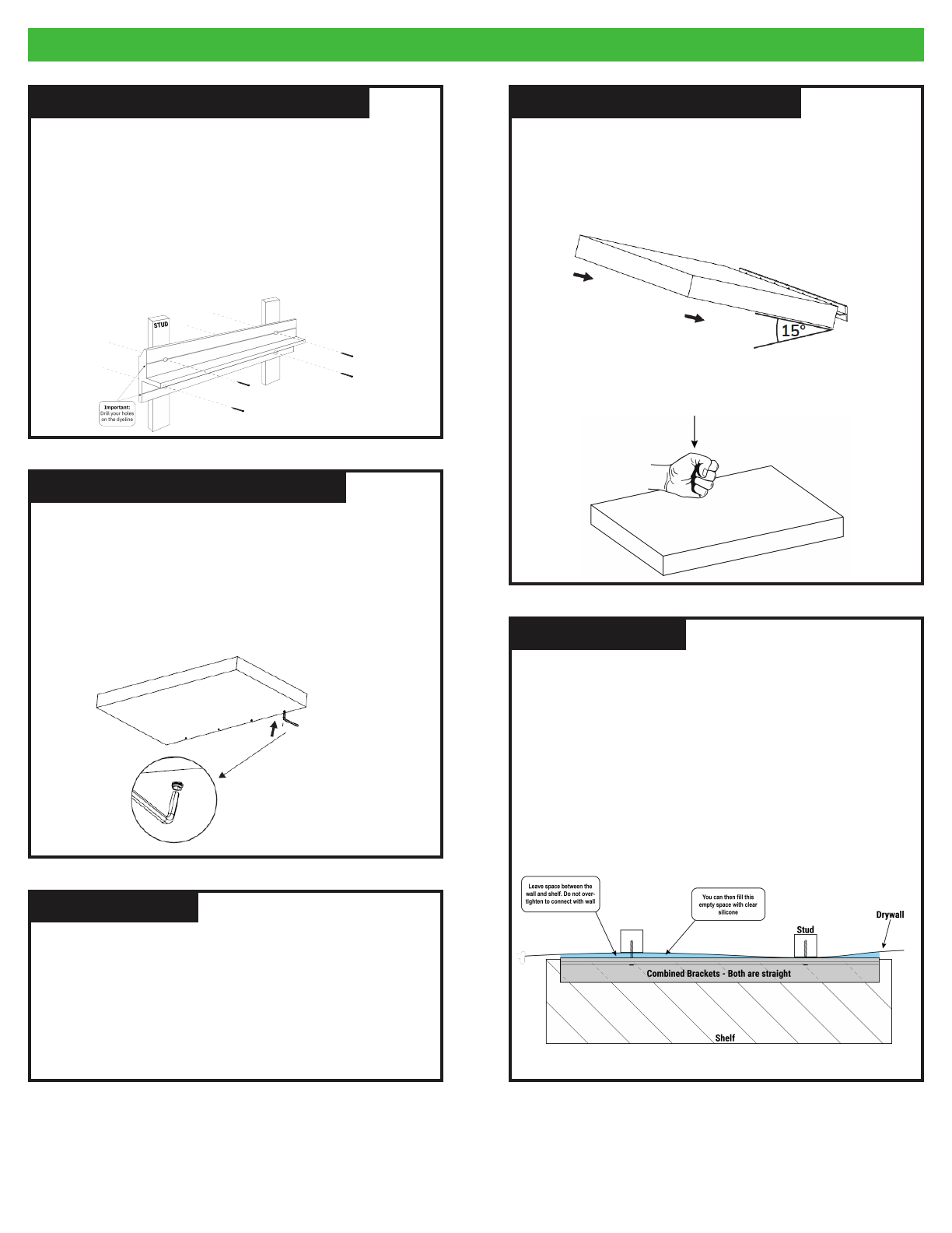
With that said, not all walls are straight. The female bracket in the
shelf is straight, so the male bracket on the wall must be straight
as well for them to engage. You can leave up to 1/4 of an inch
space between the back of the male bracket & the wall without
the integrity or holding capacity being compromised.
There are options here on how to deal with that extra space, all of
which you can find in our knowledge base online. For now, see the
below diagrams for help on dealing with a bowed wall.
IMPORTANT TIP #2IMPORTANT TIP #2
Please use the specified hardware described in this installation
guide. By not using the specific items, you may cause a loss
of integrety of the Hovr Bracket System and/or decreased
performance.
For any additional questions, please visit our help center
hovrsolutions.com/learn
IMPORTANT TIP #1IMPORTANT TIP #1

Popular Indoor Furnishing manuals by other brands

Case Hierve Vitrina quick guide

Case

Case Hierve Vitrina quick guide

IKEA FLÄRKE TV UNIT 25X17" instructions

IKEA

IKEA FLÄRKE TV UNIT 25X17" instructions

Next OHARA 315487 Assembly instructions

Next

Next OHARA 315487 Assembly instructions

Zenox Zeus PRO Series installation manual

Zenox

Zenox Zeus PRO Series installation manual

Cooper Lighting StairLite II installation instructions

Cooper Lighting

Cooper Lighting StairLite II installation instructions

2K Furniture Designs C1288 Assembly instructions

2K Furniture Designs

2K Furniture Designs C1288 Assembly instructions

Wholesale Interiors BBT6569 Assembly instructions

Wholesale Interiors

Wholesale Interiors BBT6569 Assembly instructions

Kvik H960-060 Assembly manual

Kvik

Kvik H960-060 Assembly manual

OSP MET8624 operating instructions

OSP

OSP MET8624 operating instructions

Presidential Billiards CARMEL Assembly instructions

Presidential Billiards

Presidential Billiards CARMEL Assembly instructions

Lightolier CWL specification

Lightolier

Lightolier CWL specification

Argos 411/7023 Assembly instructions

Argos

Argos 411/7023 Assembly instructions

Furniture of America CM-BK600A Assembly instructions

Furniture of America

Furniture of America CM-BK600A Assembly instructions

LF allen+roth TENBROOK ALC02917 manual

LF

LF allen+roth TENBROOK ALC02917 manual

CHITA DC71266 Assembly manual

CHITA

CHITA DC71266 Assembly manual

Safavieh Furniture ACC5707 quick start guide

Safavieh Furniture

Safavieh Furniture ACC5707 quick start guide

Forma Ideale SMART 3k2f Assembling Instruction

Forma Ideale

Forma Ideale SMART 3k2f Assembling Instruction

Dieter Knoll Collection ELVAS 992 564 Assembly instructions

Dieter Knoll Collection

Dieter Knoll Collection ELVAS 992 564 Assembly instructions

manuals.online logo
manuals.online logoBrands
  • About & Mission
  • Contact us
  • Privacy Policy
  • Terms and Conditions

Copyright 2025 Manuals.Online. All Rights Reserved.