manuals.online logo
Brands
  1. Home
  2. •
  3. Brands
  4. •
  5. Sauder
  6. •
  7. Indoor Furnishing
  8. •
  9. Sauder 411836 User manual

Sauder 411836 User manual

PLEASE CONTACT US
BEFORE RETURNING
YOUR UNIT TO THE STORE
1-800-523-3987
www.sauder.com
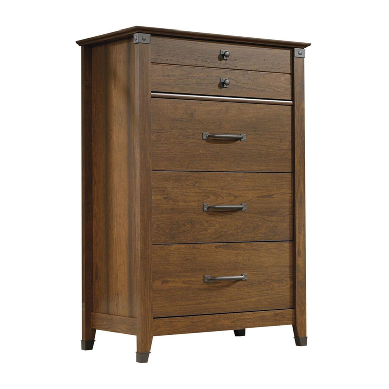
411836
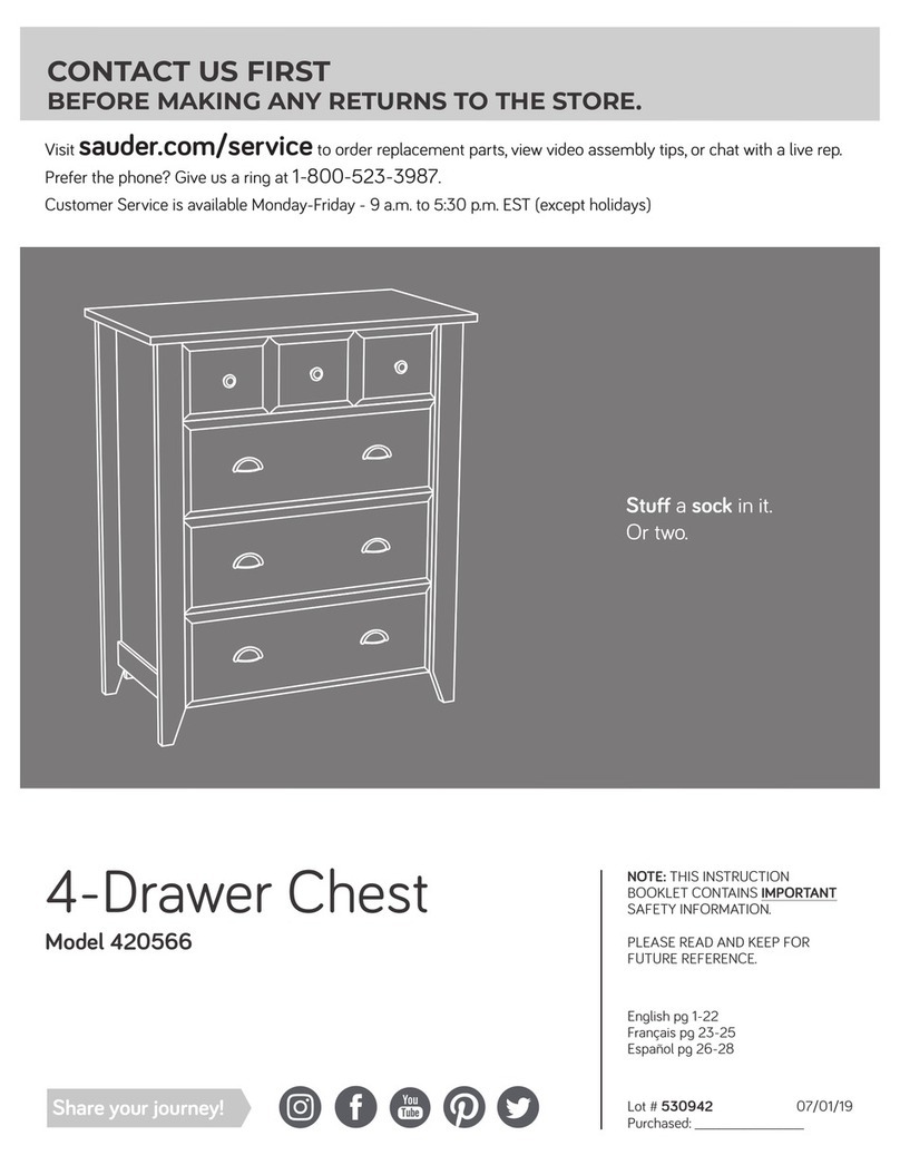
4-Drawer Chest
Palladia Collection
English.................... Page 1-24
Français...............Pages 25-28
Espanol.............Páginas 29-32
Made in the USA
Archbold, OH
NOTE: THIS INSTRUCTION BOOKLET CONTAINS
IMPORTANT SAFETY INFORMATION.
PLEASE READ AND KEEP FOR FUTURE REFERENCE.
Lot #: 353119 05 / 08 / 13
Date Purchased: ____________________
WARNING
CHOKING HAZARD - Small Parts
Not for children under 3 years.
Adult assembly required.
TABLE OF CONTENTS
Part Identification.......................3
Hardware Identification .........4-5
Assembly Steps....................6-24
Français..............................25-28
Espanol...............................29-32
Safety .................................33-34
Warranty...................................35
Page 2 www.sauder.com/services 411836
ASSEMBLY TOOLS REQUIRED
Hammer
No. 2 Phillips Screwdriver
Tip Shown Actual Size
ADULT ASSEMBLY REQUIRED
PART IDENTIFICATION: While not all parts are labeled, some of the parts will have a label or an inked
letter on the edge to help distinguish similar parts from each other. Use this PART IDENTIFICATION to help
identify similar parts.
A RIGHT END 1
B LEFT END 1
C TOP 1
D BOTTOM 1
E BACK 1
F DRAWER BRACE 4
G BASE 1
HLARGE DRAWER
FRONT 3
I LARGE DRAWER BACK 3
J LARGE DRAWER SIDE 6
K DRAWER BOTTOM 4
LSMALL DRAWER
FRONT 1
M RIGHT MOLDING 1
N LEFT MOLDING 1
O SMALL DRAWER BACK 1
P SMALL DRAWER SIDE 2
Q FRONT MOLDING 1
R2 PLINTH 2
S BOTTOM MOLDING 1
TDRAWER FRONT
MOLDING 1
U BALLAST 1
V BRACE 1
A
B
C
D
E
G
H
IJ
JK
K
L
M
N
OP
P
Q
R2
R2
S
T
U
F
F
V
Page 3
www.sauder.com/services411836
HARDWARE IDENTIFICATION
SAFETY BRACKET - 1
II
TIE PLATE - 2
EE
METAL
BRACKET - 5
JJ
HIDDEN CAM - 9
1F
TWIST-LOCK® FASTENER - 10
AA
MOLDING CONNECTOR - 2
NN
METAL PIN - 2
DD
CAM SCREW - 9
8F
GG SAFETY STOP - 4
QQ WARNING LABEL - 1
(Refer to the last step for proper location and application)
WARNING
!
Serious or fatal crushing injuries can
occur from furniture tip-over. To help
prevent tip-over:
• Place heaviest items in the lowest drawers.
• Unless specifically designed to accommodate, do not
set TVs or other heavy objects on top of this product.
• Never allow children to climb or hang on drawers,
doors, or shelves.
• Never open more than one drawer at a time.
• If equipped with a drawer interlock system, do not
defeat or remove it.
Use of tip-over restraints may only reduce,
but not eliminate, the risk of tip-over.
This is a permanent label. Do not attempt to remove!
04/10 332296
INTERLOCK TRACK - 1
OO
DRAWER FRONT BRACKET - 1
LL LARGE DRAWER FRONT BRACKET - 6
MM
KK CLIP - 16
DRAWER BOTTOM
BRACKET - 4
HH
FF DRAWER ACTUATOR - 4
KNOB - 8
PP
Page 4 www.sauder.com/services 411836
35GA CABINET RIGHT - 4 35GB CABINET LEFT - 4 35GC DRAWER RIGHT - 4
35GD DRAWER LEFT - 4
Screws are shown actual size. You may receive extra hardware with your unit.
HARDWARE IDENTIFICATION (CONTINUED)
BLACK 1-1/8” PAN HEAD SCREW - 4
TT GOLD 1” MACHINE SCREW - 2
UU
SILVER 1/2” MACHINE SCREW - 6
WW
VV BLACK 9/16” LARGE HEAD SCREW - 35
BLACK 1-1/4” FLAT HEAD SCREW - 7
SS
BROWN 1-1/2” FLAT HEAD SCREW - 4
RR
GOLD 5/16” FLAT HEAD SCREW - 32
XX NAIL - 50
YY
Page 5
www.sauder.com/services411836
Look for this icon. It means a video
assembly tip is available at:
www.sauder.com/services/tips
1
1
S
t
e
p
Assemble your unit on a carpeted floor or on the empty carton to avoid scratching your unit or the floor.
To begin assembly, push ten SAUDER TWIST-LOCK® FASTENERS (AA) into the large holes in the ENDS (A and B) and BOTTOM (D).
NOTE:
Do not tighten the TWIST-LOCK®FASTENERS at this time.
L
A
B
AA
AA
AA
Page 6 www.sauder.com/services 411836
(10 used)
2
2
S
t
e
p
Push nine HIDDEN CAMS (1F) into the BOTTOM (D), DRAWER BRACES (F) and BRACE (V).
Do not tighten the HIDDEN CAMS in this step.
Arrow
Arrow
(9 used)
Arrow
Hole
F
FFF
D
V
Page 7
www.sauder.com/services411836
1F
1F
3
3
S
t
e
p
Turn nine CAM SCREWS (8F) into the ENDS (A and B), LARGE DRAWER FRONTS (H), SMALL DRAWER FRONT (L) and
BOTTOM MOLDING (S).
(9 used) A
B
H
H
H
L
S
Page 8 www.sauder.com/services 411836
8F
4
4
S
t
e
p
Tap two MOLDING CONNECTORS (NN) into the notches in the MOLDINGS (M, N and Q).
Fasten the MOLDINGS (M, N, and Q) to the TOP (C). Use seven BLACK 1-1/4" FLAT HEAD SCREWS (SS).
Flat end Flat end
Use your hammer to tap the MOLDING CONNECTOR (NN) into the notches in the MOLDINGS.
BLACK 1-1/4” FLAT HEAD SCREW
(7 used in this step)
SS
M
M
N
N
Q
Q
Rounded edge
C
NN NN
Unfinished surface
Unfinished surface Unfinished surface
Finished surface
Finished surface
Finished surface
Page 9
www.sauder.com/services411836
The next three steps involve an important safety feature designed to prevent more than one drawer from opening at the same time.
Insert four SAFETY STOPS (GG) into the holes shown in the RIGHT END (A).
5
5
S
t
e
p
This pin must insert into the location
holes in the RIGHT END (A).
GG
GG
A
Page 10 www.sauder.com/services 411836
Diagram 1. Measure 3” from one end of the INTERLOCK TRACK (OO).
Position the INTERLOCK TRACK as shown.
SAFETY STOP / TRACK ATTACHMENT:
Diagram 2. Tilt the first edge of the INTERLOCK TRACK (OO) into the SAFETY STOP (GG).
Diagram 3. Rotate the INTERLOCK TRACK and apply force to snap the second edge into the SAFETY STOP.
Diagram 4. Repeat the SAFETY STOP/ TRACKATTACHMENT for the next SAFETY STOPS while holding the previously
completed SAFETY STOP in its location hole. Visually check that all INTERLOCK TRACK edges have been snapped into the
SAFETY STOPS as shown in diagram 3.
Diagram 5. Remove the INTERLOCK TRACK assembly from Diagram 4 and flip it over before inserting the INTERLOCK TRACK (OO)
with SAFETY STOPS (GG) into the groove in the RIGHT END (A).
6
6
S
t
e
p
2. 3.
1.
3"
4.
5.
Be sure the
interlock track
snaps into each
safety stop.
OO
OO
OO
GG
GG
The interlock system is a safety feature that prevents
more than one drawer from opening at the same time.
Do not use excessive force to open the drawers.
Page 11
www.sauder.com/services411836
A
A
F
l
i
p
o
v
e
r
a
n
d
i
n
s
e
r
t
i
n
t
o
g
r
o
o
v
e
.
Fasten the CABINET RIGHTS (35GA) and CABINET LEFTS (35GB) to the ENDS (A and B). Use sixteen GOLD 5/16" FLAT
HEAD SCREWS (XX) through holes #1 and #3.
7
7
S
t
e
p
A
B
1
2
332
1
3
2
1
3
2
1
3
2
1
1
2
3
1
2
3
1
2
3
GOLD 5/16" FLAT HEAD SCREW
(16 used in this step)
XX
Page 12 www.sauder.com/services 411836
Roller end
Roller end
Insert two METAL PINS (DD) into the short edges of the BRACE (V).
Fasten the BRACE (V) to the ENDS (A and B). Tighten two HIDDEN CAMS.
NOTE: Be sure the METAL PINS insert into the holes in the ENDS.
8
8
S
t
e
p
A
B
Finished edge Finished edge
Finished edge
DD
DD
V
Page 13
www.sauder.com/services411836
Surface with
HIDDEN CAMS
Fasten the TOP MOLDINGS (M and N) to the ENDS (A and B). Tighten four TWIST-LOCK®FASTENERS.
Fasten the BOTTOM (D) to the ENDS (Aand B). Tighten four TWIST-LOCK®FASTENERS.
9
9
S
t
e
p
How to use the SAUDER TWIST-LOCK®FASTENER
1. Insert the dowel end of the FASTENER into the
hole of the adjoining part.
NOTE: The dowel end of the FASTENER must remain
fully inserted in the hole of the adjoining part while
locking the FASTENER.
2. Tighten the FASTENER with a Phillips screwdriver
as tight as possible.
Dowel end
M
NA
BD
Page 14 www.sauder.com/services 411836
Surface with
TWIST-LOCK® FASTENERS
These holes
must be here.
Fasten the BOTTOM MOLDING (S) to the BOTTOM (D). Tighten three HIDDEN CAMS.
Fasten two METAL BRACKETS (JJ) to the BOTTOM (D). Use two BLACK 9/16" LARGE HEAD SCREWS (VV).
Fasten the PLINTHS (R2) to the ENDS (A and B). Tighten two TWIST-LOCK®FASTENERS.
Fasten the PLINTHS (R2) to the BOTTOM (D). Use two BLACK 9/16" LARGE HEAD SCREWS (VV).
10
10
S
t
e
p
A
B
BLACK 9/16” LARGE HEAD SCREW
(4 used for the METAL BRACKETS)
VV
D
Unfinished
Coved edge
Coved edge
S
R2
R2
Page 15
www.sauder.com/services411836
JJ
Fasten the BALLAST (U) to the BOTTOM (D). Use four BLACK 1-1/8" PAN HEAD SCREWS (TT).
Fasten three METAL BRACKETS (JJ) to the BALLAST (U). Use three BLACK 9/16" LARGE HEAD SCREWS (VV).
Fasten the BASE (G) to the BALLAST (U). Use three BLACK 9/16" LARGE HEAD SCREWS (VV).
11
11
S
t
e
p
BLACK 1-1/8” PAN HEAD SCREW
(4 used in this step)
TT
U
BLACK 9/16” LARGE HEAD SCREW
(6 used for the METAL BRACKETS)
VV
Page 16 www.sauder.com/services 411836
JJ
G
Carefully turn your unit over onto its front edges. Unfold the BACK (E) and lay it over your unit.
Make equal margins along all four edges of the BACK (E). Push on opposite corners of your unit if needed to make it “square”.
Fasten the BACK (E) to your unit using the NAILS (YY).
Fasten two TIE PLATES (EE) to the PLINTHS (R2) and BASE (G). Use four BLACK 9/16" LARGE HEAD SCREWS (VV).
12
12
S
t
e
p
Do not stand the unit upright without the
BACK fastened. The unit may collapse.
Caution
NAIL
(34 used in this step)
YY
BLACK 9/16” LARGE HEAD SCREW
(4 used for the TIE PLATES)
VV
EE
G
R2
R2
E
Page 17
www.sauder.com/services411836
Printed information
must be facing up.
Fasten the DRAWER FRONT MOLDING (T) to the SMALL DRAWER FRONT (L). Use three BROWN 1-1/2" FLAT HEAD
SCREWS (RR).
13
13
S
t
e
p
Unfinished edge
BROWN 1-1/2” FLAT HEAD SCREW
(3 used in this step)
RR
T
Groove
L
Page 18 www.sauder.com/services 411836
Pull the DRAWER FRONT BRACKETS (LL and MM) apart and slide them into the grooves in the DRAWER SIDES (J and P).
Fasten the DRAWER FRONTS (H and L) to the DRAWER FRONT BRACKETS. Use sixteen BLACK 9/16” LARGE HEAD
SCREWS (VV).
Slide the DRAWER BOTTOMS (K) into the DRAWER SIDES (P and J).
14
14
S
t
e
p
Push down
BLACK 9/16” LARGE HEAD SCREW
(16 used in this step)
VV
LL
LL
Tap down with your screwdriver and hammer.
K
J
J
P
P
P
P
L
H
Groove
Groove
Groove
Groove
Page 19
www.sauder.com/services411836
Slide the SMALL DRAWER BACK (O) into the grooves in the SMALL DRAWER SIDES (P).
Flip the drawer over and fasten the DRAWER BRACE (F) to the SMALL DRAWER FRONT (L). Tighten the HIDDEN CAM.
Insert the DRAWER BOTTOM BRACKET (HH) into the groove in the SMALL DRAWER BACK (O) and wrap it over the DRAWER
BRACE (F). Fasten the BRACKET (HH) to the DRAWER BRACE (F). Use a BLACK 9/16” LARGE HEAD SCREW (VV).
Insert four CLIPS (KK) into the groove in the SMALL DRAWER BACK (O) and wrap them over the DRAWER BOTTOM (K). Tap
a NAIL (YY) through each CLIP.
NOTE: The CLIPS should set in about 1" from the SMALL DRAWER SIDES.
Repeat this step for the other drawers.
15
15
S
t
e
p
Slide the DRAWER
BACK down.
BLACK 9/16” LARGE HEAD SCREW
(4 used for the DRAWER BOTTOM BRACKETS)
VV
Groove
NAIL
(16 used for the CLIPS)
YY
Surface with
HIDDEN CAM
O
P
P
HH
KK
F
(16 used)
(4 used)
Page 20 www.sauder.com/services 411836
O
L
K

Other Sauder Indoor Furnishing manuals
Sauder Whitaker Point 429374 User manual

Sauder

Sauder Whitaker Point 429374 User manual

Sauder Edge Water Series User manual

Sauder

Sauder Edge Water Series User manual

Sauder worksense BERGEN CIRCLE 427464 User manual

Sauder

Sauder worksense BERGEN CIRCLE 427464 User manual

Sauder OFFICE WORKS AFFIRM 427438 User manual

Sauder

Sauder OFFICE WORKS AFFIRM 427438 User manual

Sauder Edge Water 422406 User manual

Sauder

Sauder Edge Water 422406 User manual

Sauder Shoal Creek 418662 User manual

Sauder

Sauder Shoal Creek 418662 User manual

Sauder 412740 User manual

Sauder

Sauder 412740 User manual

Sauder Jaclyn Smith Gatsby 415693 User manual

Sauder

Sauder Jaclyn Smith Gatsby 415693 User manual

Sauder 411606 User manual

Sauder

Sauder 411606 User manual

Sauder Steel River 423976 User manual

Sauder

Sauder Steel River 423976 User manual

Sauder OfficeWorks AFFIRM 427427 User manual

Sauder

Sauder OfficeWorks AFFIRM 427427 User manual

Sauder Carson Forge Collection 415117 User manual

Sauder

Sauder Carson Forge Collection 415117 User manual

Sauder OfficeWorks AFFIRM 426277 User manual

Sauder

Sauder OfficeWorks AFFIRM 426277 User manual

Sauder Edge Water 408696 User manual

Sauder

Sauder Edge Water 408696 User manual

Sauder Armoire 419451 User manual

Sauder

Sauder Armoire 419451 User manual

Sauder Palladia Collection Credenza 412079 User manual

Sauder

Sauder Palladia Collection Credenza 412079 User manual

Sauder Dakota Pass 422596 User manual

Sauder

Sauder Dakota Pass 422596 User manual

Sauder Executive Desk 408289 User manual

Sauder

Sauder Executive Desk 408289 User manual

Sauder Cannery Bridge 429556 User manual

Sauder

Sauder Cannery Bridge 429556 User manual

Sauder 420406 User manual

Sauder

Sauder 420406 User manual
Sauder WHISKER CAT PYRAMID User manual

Sauder

Sauder WHISKER CAT PYRAMID User manual

Sauder Shoal Creek 410287 User manual

Sauder

Sauder Shoal Creek 410287 User manual

Sauder 422893 User manual

Sauder

Sauder 422893 User manual

Sauder Via 419606 User manual

Sauder

Sauder Via 419606 User manual

Popular Indoor Furnishing manuals by other brands

dg casa 12350-Q Assembly instruction

dg casa

dg casa 12350-Q Assembly instruction

Seville Classics NSF ULTRADURABLE SHE24605/Z quick start guide

Seville Classics

Seville Classics NSF ULTRADURABLE SHE24605/Z quick start guide

Costway HV10016 user manual

Costway

Costway HV10016 user manual

CONSET SQ147250 Assembly instruction

CONSET

CONSET SQ147250 Assembly instruction

OSP Designs AURORA AR30 Assembly instructions

OSP Designs

OSP Designs AURORA AR30 Assembly instructions

Telford CORNER DESK Assembly instructions

Telford

Telford CORNER DESK Assembly instructions

Bali MOTORIZED SHADES owner's manual

Bali

Bali MOTORIZED SHADES owner's manual

Starspace BTX-289 instruction manual

Starspace

Starspace BTX-289 instruction manual

Home Decorators FRA60624ALVW Use and care guide

Home Decorators

Home Decorators FRA60624ALVW Use and care guide

RiverRidge ASHLAND SINGLE DOOR / 3 DRAWER CABINET Assembly instructions

RiverRidge

RiverRidge ASHLAND SINGLE DOOR / 3 DRAWER CABINET Assembly instructions

Bon Pergola Villa Pergola Double Bay User instructions

Bon Pergola

Bon Pergola Villa Pergola Double Bay User instructions

Wellis WB00376 Instruction guide

Wellis

Wellis WB00376 Instruction guide

PREMIER POLYSTEEL Champion 924-507 manual

PREMIER POLYSTEEL

PREMIER POLYSTEEL Champion 924-507 manual

Cooper Lighting Lumiere Westwood 913 Specification sheet

Cooper Lighting

Cooper Lighting Lumiere Westwood 913 Specification sheet

Okamura CYNARA Instructions for use

Okamura

Okamura CYNARA Instructions for use

FourStarGroup 11223182F Assembly instructions

FourStarGroup

FourStarGroup 11223182F Assembly instructions

Teknion height-adjustable bench Installation guides

Teknion

Teknion height-adjustable bench Installation guides

INNER STRENGHT Tech Series Setup guide

INNER STRENGHT

INNER STRENGHT Tech Series Setup guide

manuals.online logo
manuals.online logoBrands
  • About & Mission
  • Contact us
  • Privacy Policy
  • Terms and Conditions

Copyright 2025 Manuals.Online. All Rights Reserved.