Document 2.4.126, Revision 4
October 2017
7
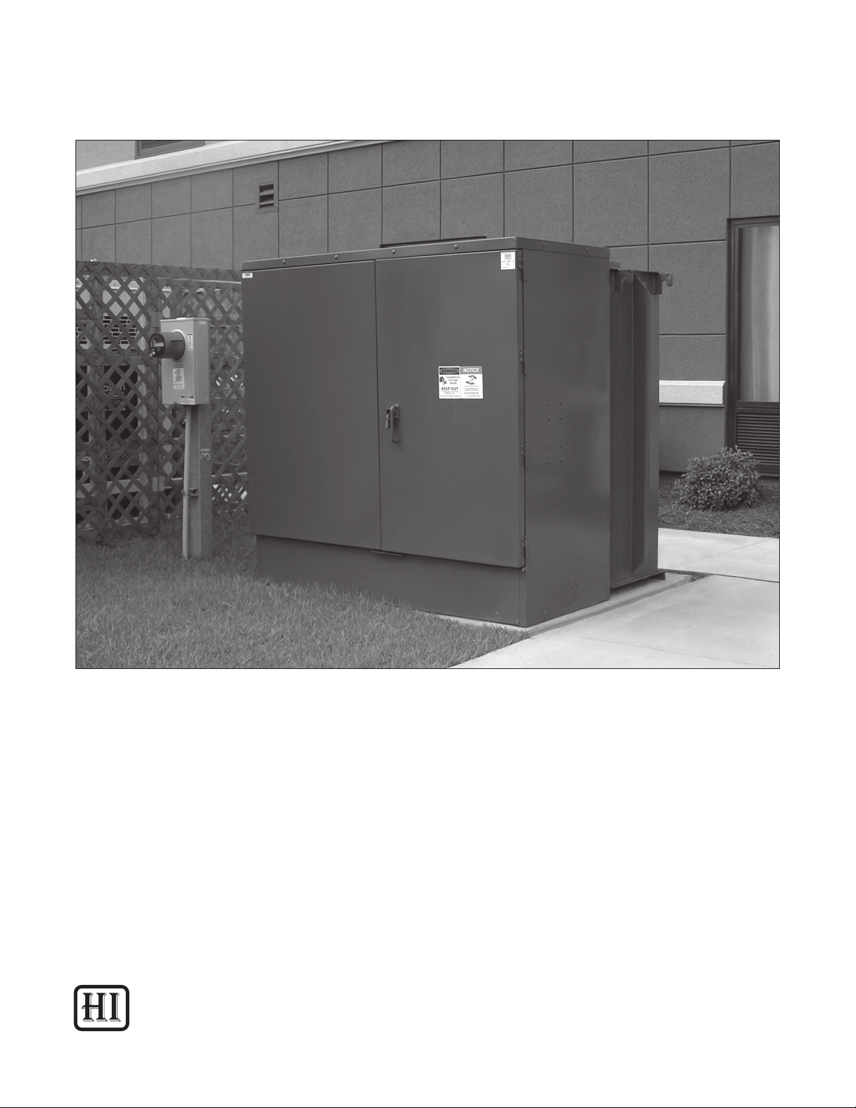
Three-Phase Padmounted Distribution Transformers
air. A rising or falling reading that varies over
time with ambient temperature indicates that
the transformer tank is sealed effectively. If the
vacuum/pressure gauge shows a constant zero
reading, this indicates the possibility of a tank leak.
If this occurs, the tank should be checked carefully
for leaks as indicated in the following step.
4. Check the tank for indication of uid leaks,
looking carefully at weld seams, bushings,
gauges, valves and all other tank ttings. If
suspicious indications are found, investigate
thoroughly to determine if a leak does exist
on the transformer. Indications of a leak
can sometimes be residual uid that was not
cleaned during the manufacturing process
and not an actual leak. In many cases a small
pinhole tank leak or leak from a bushing, gauge,
valve or other tting can be easily repaired on
site. Refer to the “Maintenance” section for
information about the repair of uid leaks.
5. Check for external damage including dents
or scratches on the tank walls, radiators and
terminal compartment. Dents and scratches
can often be repaired on site using simple
touch-up procedures. If touch-up painting
is performed, do not remove or obscure
any warning labels, instructional labels or
nameplates.
6. Check for broken, cracked, or damaged
bushings, gauges, valves and other ttings and
accessories.
7. Check for missing or damaged component parts
and packages that shipped separately from the
transformer.
Fluid Level
The transformer is shipped from the factory with
dielectric uid lled to the proper level. Before
energizing the transformer, verify proper uid level
by observing the uid level gauge. The uid level
gauge pointer should be between the “High” and
“Low” marks. For transformers supplied with a uid
sight plug, the uid level can be directly observed
if it is within acceptable range. If the transformer
does not have a uid level gauge or sight plug, the
uid level can be checked by removing the liquid
level plug located at the 25° C mark. Exercise
caution when checking the uid level using the uid
level plug, as the uid may spill out and may be
extremely hot. When checking the uid level, bear
in mind that the level will vary as a function of uid
temperature.
A transformer found to have a low uid level should
be checked for potential leaks and lled to the
proper level with the same type of liquid as that
specied on the transformer nameplate.
Internal Inspection
An internal inspection of the transformer tank is
rarely necessary and is recommended only when
there are obvious indications that the transformer
has received severe impact damage during transit
or when necessary to perform recommended pre-
energization tests or inspections. Do not open the
transformer tank without authorization from the
Howard Industries Transformer Division.
If the transformer tank must be opened, refer to
“Opening the Transformer Tank” for instructions.
Fluid Sampling
Sampling and testing of the uid is not required
unless there is indication that moisture or other
contaminants have accidently entered the tank
during transit. If moisture or contaminates in the
uid is suspected, contact the Howard Industries
Transformer Division immediately for instructions.
If uid sampling is required, refer to “Sampling the
Fluid” for instructions.
WARNING
FAILURE TO FOLLOW THE INSTRUCTIONS
BELOW MAY CAUSE DEATH OR SERIOUS
PERSONAL INJURY AND/OR DAMAGE TO
THE EQUIPMENT.
• Do not energize the transformer if the
uid level is low.
• Maintain proper uid level at all times
while the transformer is energized.
• Exercise caution when checking the uid
level with the uid level plug, as the uid
may spill and may be extremely hot.