HP 8340b User manual

Errata
Title & Document Type:
Manual Part Number:
Revision Date:
HP References in this Manual
This manual may contain references to HP or Hewlett-Packard. Please note that Hewlett-
Packard's former test and measurement, semiconductor products and chemical analysis
businesses are now part of Agilent Technologies. We have made no changes to this
manual copy. The HP XXXX referred to in this document is now the Agilent XXXX.
For example, model number HP8648A is now model number Agilent 8648A.
About this Manual
We’ve added this manual to the Agilent website in an effort to help you support your
product. This manual provides the best information we could find. It may be incomplete
or contain dated information, and the scan quality may not be ideal. If we find a better
copy in the future, we will add it to the Agilent website.
Support for Your Product
Agilent no longer sells or supports this product. You will find any other available
product information on the Agilent Test & Measurement website:
www.tm.agilent.com
Search for the model number of this product, and the resulting product page will guide
you to any available information. Our service centers may be able to perform calibration
if no repair parts are needed, but no other support from Agilent is available.
8340B/8341B Synthesized Sweeper Manual
08340-90243
August 1986

AttIMiCT Li^L ;lilM1:^ ^.li JIL^L
HP 8340B
HP 8341B
SYNTHESIZED
SWEEPERS
-^ ^^ • - gg ggyg
uuu o ooo _ esQ UUQO
_j_jau :aLjL_iLj UU ou UUOU
tr 'Q" ^{?
HEWLETT
PACKARD

HP 8340B
SYNTHESIZED SWEEPER
(Including Options 001, 004,
005, 006, and 007)
HP 8341B
SYNTHESIZED SWEEPER
(Including Option 004)
SERIAL NUMBERS
This manual applies directly to the HP 8340B Synthesized
Sweeper having a serial number prefix of 2624A and the HP 8341 B
Synthesized Sweeper prefixed 2624A.
For additional information about serial numbers, refer to
INSTRUMENTS COVERED BY THE MANUAL In Section I.
• Manual Changes Supplement Print Date: 03 DEC 1990 Rev. 15
Change Documents
Prefix Change Documents
Prefix
2634A
2643A
2650A
2730A
2802A
2804A
2812A
2819A
291 OA
10
11
12
13
14
15
16
2920A
2928A
3006A
3008A
3010A
3009A
30 ISA
3050A
© Copyright HEWLETT-PACKARD COMPANY 1986
1400 FOUNTAINGROVE PARKWAY, SANTA ROSA, CA 95401 U.S.A.
MANUAL PART NO. 08340-90243
Microfiche Part Number 08340-90244 Printed: AUGUST 1986
(^ HEWLETT
PACKARD

HP 8340B/41B Assembly-Level Service
CONTENTS
SERVICE INTRODUCTION ......................................................A
Introduction ................................................................. A-1
Overall Instrument Theory ...................................................... A-4
Calibration Constants ........................................................ A-11
Troubleshooting Aids ........................................................ A-25
Front Panel Diagnostics ...................................................... A-26
Overall Instrument Troubleshooting ............................................. A-31
Repair Procedures .......................................................... A-50
After Service Safety Checks .................................................. A-51
REFERENCE LOOP - M/N LOOP ................................................. B
Reference Loop - M/N Loop Introduction ......................................... B-1
Reference Loop Theory of Operation ............................................ B-2
M/N Loop Theory of Operation ................................................. B-4
Reference Loop Assembly-Level Troubleshooting .................................. B-9
M/N Loop Assembly-Level Troubleshooting ...................................... B-21
Repair Procedures .......................................................... B-44
Replaceable Parts ........................................................... B-51
20-30 LOOPS .................................................................. C
Introduction ................................................................. C-1
Overall Theory of Operation .................................................... C-2
20-30 Loops Assembly-Level Troubleshooting .................................... C-11
Replaceable Parts ........................................................... C-20
SWEEP GENERATOR - YO LOOP ................................................ D
Introduction ................................................................. D-1
Theory of Operation .......................................................... D-2
YO Loop Assembly-Level Troubleshooting ....................................... D-15
Sweep Generator Assembly-Level Troubleshooting ................................ D-24
A23 FM Driver Assembly-Level Troubleshooting ................................... D-26
Repair Procedures .......................................................... D-36
Replaceable Parts ........................................................... D-40
MOTHERBOARD AND WIRING LIST ............................................. E
A62 Motherboard Overall Description ...................................... ..... E-1
A62 Motherboard Wiring List ................................................... E-3
HP 8340B/41B Table of Contents

CONTENTS (Cont'd)
CONTROLLER SECTION ........................................................ F
Introduction ................................................................. F-1
Theory of Operation .......................................................... F-2
Overall Assembly-Level Troubleshooting .......................................... F-9
A57 Marker/Bandcross Assembly-Level Troubleshooting ............................ F-10
A59 Digital Interface Assembly-Level Troubleshooting .............................. F-11
A60 Processor Assembly-Level Troubleshooting ................................... F-13
Repair Procedure ............................................................ F-26
Replaceable Parts ........................................................... F-28
FRONT PANEL - REAR PANEL .................................................. G
Introduction ................................................................. G-1
Front Panel Theory of Operation ................................................ G-2
Front Panel Overall Assembly-Level Troubleshooting ................................ G-6
A3 Display Processor Assembly-Level Troubleshooting .............................. G-8
A5 Keyboard & A7 Lower Keyboard Assembly-Level Troubleshooting ................. G-10
A6 Keyboard Interface Assembly-Level Troubleshooting ............................ G-11
Front Panel Repair Procedure ................................................. G-16
Front Panel Replaceable Parts ................................................. G-25
Rear Panel Theory of Operation ................................................ G-40
Rear Panel Assembly-Level Troubleshooting ..................................... G-51
Rear Panel Replaceable Parts ................................................. G-55
RF SECTION ..................................................................H
Introduction ................................ ................................ H-1
Theory of Operation .......................................................... H-2
Overall Assembly-Level Troubleshooting ......................................... H-15
SYTM Peaking Assembly-Level Troubleshooting .................................. H-19
ALC Loop Assembly-Level Troubleshooting ...................................... H-21
RF Path Assembly-Level Troubleshooting ........................................ H-25
Repair Procedures .......................................................... H-35
Replaceable Parts ........................................................... H-48
POWER SUPPLIES/FAN ......................................................... I
Introduction .................................................................. 1-1
Theory of Operation ........................................................... 1-2
Assembly-Level Troubleshooting ................................................. 1-9
Repair Procedures ........................................................... 1-18
Replaceable Parts ........................................................... 1-24
Table of Contents HP 8340B/41B

CONTENTS (Cont'd)
MAJOR ASSEMBLIES AND COMPONENTS LOCATION - CHASSIS PARTS .......... J
MAJOR ASSEMBLIES AND COMPONENTS LOCATION
Figure J-1. Front Panel Assemblies ........................................... J-1
Figure J-2. Top View ........................................................J-2
Figure J-3. Bottom View ..................................................... J-3
MISCELLANEOUS MECHANICAL AND CHASSIS PARTS
Figure J-4. Miscellaneous Mechanical and Chassis Parts .........
Table J-1. Replaceable Miscellaneous Mechanical and Chassis Parts
OPTION CONFIGURATIONS
Table J-2. HP 8340B Option Configurations ....................
Table J-3. HP 8341 B Option Configurations ....................
.J-5
J-10
J-13
J-14
HP 8340B/41B Table of Contents lii/iv

HP 8340B/41B Assembly-Level
Service Introduction
CONTENTS
INTRODUCTION .............................................................. A-1
Manual Format .................................................. ............ A-1
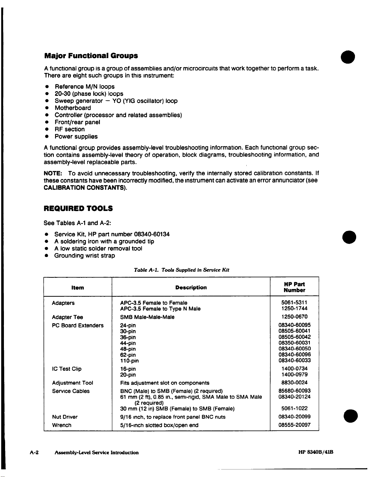
Required Tools .............................................................. A-2
Interconnect Cables and Mnemonics ............................................. A-3
OVERALL INSTRUMENT THEORY ............................................. A-4-
Reference Loops ............................................................. A-4
M/N Loop ................................................................... A-4
20-30 Loops ................................................................. A-5
YO Loop .................................................................... A-5
Controller Section ............................................................ A-5
Front Panel-Rear Panel ........................................................ A-6
RF Section .................................................................. A-6
Power Supplies .............................................................. A-7
HP 8340B/41B Block Diagram .................................................. A-9
CALIBRATION CONSTANTS .................................................. A-11
Instrument Access ........................................................... A-11
User Access ................................................................ A-13
Calibration Constants Description .............................................. A-16
How to Restore Factory-Optimized Calibration Constants ........................... A-23
TROUBLESHOOTING AIDS ................................................... A-25
Self Test ................................................................... A-25
Phase-Lock Indication LEDs ................................................... A-25
Power Supply Indication LEDs ................................................. A-25
FRONT PANEL DIAGNOSTICS ................................................ A-26
Shift Manual ................................................................ A-27
Shift Free Run ........................................................... A-27
Shift Ext ................................................................... A-27
Shift M1 ................................................................... A-28
Shift M2 .................................................................. A-28
Shift M3 ................................................................... A-28
Shift M4 ................................................................... A-29
Shift M5 ................................................................ ,. A-29
Shift RF .................................................................. A-29
Shift Meter ................................................................ A-29
Shift Peak ............................................................... A-30
Shift Pwr Sweep ............................................................ A-30
Shift Slope ................................................................. A-30
HP 8340B/41B Table of Contents

CONTENTS (Cont'd)
OVERALL INSTRUMENT TROUBLESHOOTING ................................. A-31
Overall Instrument Troubleshooting Diagram ..................................... A-34
Front and Rear Panel Items ................................................... A-35
Instrument Preset Conditions (1) ................................................ A-36
Instrument Appears Dead (2) .................................................. A-37
Fan Runs Slowly, All LEDs On(but dim) ......................................... A-37
Fan (3) .................................................................... A-37
Instrument Check LEDs Remain On (4) .......................................... A-38
Oven Annunciator (5) ......................................................... A-38
Unlock Annunciator (6) ....................................................... A-39
Fault Annunciator (7) ........................................................ A-40
Unleveled Annunciator (8) ..................................................... A-41
Overmod Annunciator(9) ...................................................... A-41
SRQ Annunciator (10) ........................................................ A-42
Upper Keyboard, Lower Keyboard, Displays (11,12,13) ............................. A-42
Frequency (14) ............................................................. A-43
Power (15) ................................................................. A-43
Sweep (16) ................................................................. A-44
Spectral Purity/Harmonics (17,18) .............................................. A-45
I/O Connectors (19) .......................................................... A-49
Remote Operation (20) ....................................................... A-49
REPAIR PROCEDURES ....................................................... A-50
How to Clean Printed Circuit board Fingers ....................................... A-50
Module Exchange Program ................................................... A-50
AFTER SERVICE SAFETY CHECKS ........................................... A-51
Visual Inspection ............................................................ A-51
Check Line Cord Ground ...................................................... A-51
Check the Line/Neutral ....................................................... A-51
Check the Line Fuse ......................................................... A-51
Air Filter Replacement ........................................................ A-52
ASSEMBLY PIN I/O TABLES ................................................. A-53
ii Table of Contents HP 8340B/41B

HP 8340B/41B Assembly-Level Service
Introduction
This manual provides assembly-level troubleshooting information for both the HP 8340B and the
8341B synthesized sweepers.
MANUAL FORMAT
Introduction
The introduction provides information on:
• Manual format.
• The tools required to service the instrument.
• Interconnect cables and mnemonics.
Overall Instrument Theory
This portion details overall instrument theory of operation, and includes an overall instrument block
diagram.
Calibration Constants
This is a description of the instrument's stored calibration constants.
Troubleshooting Aids
This part of the service section contains descriptions of the troubleshooting aids built into the
instrument:
• The instrument self-test
• Front panel diagnostics.
Overall Instrument Troubleshooting
This troubleshooting guide begins with a symptom and leads you to one of the eight major
functional areas of the instrument (see below). In some cases, this guide leads you directly to the
faulty assembly.
Repair
This section contains cautions concerning the repair of the HP 8340B/41B. Please read these
cautions. They contain important notices concerning personal safety and instrument repair.
This section also contains a description of the module exchange program, and after service safety
checks.
HP 8340B/41B Assembly-Level Service Introduction A-l

Major Functional Groups
A functional group is a group of assemblies and/or microcircuits that work together to perform a task.
There are eight such groups in this instrument:
Reference M/N loops
20-30 (phase lock) loops
Sweep generator — YO (YIG oscillator) loop
Motherboard
Controller (processor and related assemblies)
Front/rear panel
RF section
Power supplies
A functional group provides assembly-level troubleshooting information. Each functional group sec¬
tion contains assembly-level theory of operation, block diagrams, troubleshooting information, and
assembly-level replaceable parts.
NOTE: To avoid unnecessary troubleshooting, verify the internally stored calibration constants. If
these constants have been incorrectly modified, the instrument can activate an error annunciator (see
CALIBRATION CONSTANTS).
REQUIRED TOOLS
See Tables A-1 and A-2:
• Service Kit, HP part number 08340-60134
• A soldering iron with a grounded tip
• A low static solder removal tool
• Grounding wrist strap
Table A-1. Tools Supplied in Service Kit
Item
Adapters
Adapter Tee
PC Board Extenders
1C Test Clip
Adjustment Tool
Service Cables
Nut Driver
Wrench
Description
APC-3.5 Female to Female
APC-3.5 Female to Type N Male
SMB Male-Male-Male
24-pin
30-pin
36-pin
44-pin
48-pin
62-pin
110-pin
16-pin
20-pin
Fits adjustment slot on components
BNC (Male) to SMB (Female) (2 required)
61 mm (2 ft), 0.85 In., semi-rigid, SMA Male to SMA Male
(2 required)
30 mm (12 in) SMB (Female) to SMB (Female)
9/16 inch, to replace front panel BNC nuts
5/16-inch slotted box/open end
HP Part
Number
5061-5311
1250-1744
1250-0670
08340-60095
08505-60041
08505-60042
08350-60031
08340-60050
08340-60096
08340-60033
1400-0734
1400-0979
8830-0024
85680-60093
08340-20124
5061-1022
08340-20099
08555-20097
Assembly-Level Service Introduction HP 8340B/41B

Table A-2. Equipment Required but not Supplied in the Service Kit
Item
RMA Solder
EDSYN
SILVERSTAT
Replacement Tip
Wrist Strap
Description
Rosin Mildly Activated
Low static solder removal tool
For low-static solder removal tool
Anti-static wrist strap, 4 ft cord and alligator clip
HP Part
Number
8090-0587
8690-0227
8690-0253
9300-0791
INTERCONNECT CABLES AND MNEMONICS
All interconnect cables and their associated connectors are listed in the A62 motherboard functional
group.
All signal mnemonics are defined, the point-to-point distribution of each signal to and from the PC
board sockets and the cable connectors on the A62 motherboard assembly are referenced, and the
assembly that generated the signal is defined in the A62 motherboard functional group.
HP 8340B/41B Assembly-Level Service Introduction

HP 8340B/41B Assembly-Level Service
Overall Instrument Theory
The HP 8340B is a synthesized sweeper that covers the frequency range from 10 MHz to 26.5 GHz, in
five bands.
The HP 8341B is a synthesized sweeper that covers the frequency range from 10 MHz to 20.0 GHz, in
four bands.
The instrument bands are:
• Band 0
10 MHz to 2.3 GHz
• Band 1
2.3 to 7.0 GHz
• Band 2
7.0 to 13.5 GHz
• Band 3
13.5 to 20.0 GHz
• Band 4
20.0 to 26.5 GHz (HP 8340B only)
Internal to the instrument are 7 phase-lock loops, 17 high frequency microcircuits, and a 16-bit micro¬
processor.
REFERENCE LOOPS
Frequency accuracy and stability are tied to either the 10 MHz internal frequency standard or an
external 5 orlO MHz source. The reference loop uses this 10 MHz to generate all of the translation and
reference signals used by other phase-lock loops in the instrument. These signals are:
• 400 MHz and 20 MHz signals used in the M/N loop to produce the M/N output frequency.
• 10 MHz and 100 MHz signals used as reference signals in the 20-30 loops.
• A separate, lower power 100 MHz output sent to the RF section to phase lock the 3.7 GHz
oscillator to the 10 MHz reference.
M/N LOOP
The M/N loop produces an output between 177 and 197 MHz that drives a sampler in the YO loop. The
variables M and N are integers generated by the processor, and control the output frequency of the
M/N loop. The output from the sampler in the YO loop must always be between 20 and 30 MHz to be
compared and phase locked to the output of the 20-30 phase lock loops.
With the YO at a specific frequency between 2.3 and 7.0 GHz, there is an M/N output frequency
between 177 and 197 MHz. When a harmonic of this frequency is mixed with the YO frequency in the
sampler, an IF output between 20 and 30 MHz results. The sampler output is then compared to the
20-30 loop output by the YO loop phase/frequency detector in the YO loop.
A-4 Assembly-Level Service Overall Instrument Theory HP 8340B/41B

20-30 LOOPS
The 20-30 loops contain three phase-locked loops used together to provide the YO loop with 1 Hz CW
resolution, and with analog sweep widths from 100 Hz to 5 MHz- For sweep widths of 5 MHz or less,
the YO Loop remains phase-locked during the sweep, and the 20-30 Loop is swept the desired
amount. For sweep widths greater than 5 MHz, all phase-lock loops lock at the beginning of sweep,
the 20-30 Loop remains fixed, and the YO is swept. This is called lock and roll, and will be discussed
later.
The 20-30 loop generates an output between 20 and 30 MHz in CW mode, and between 15 and 30
MHz when swept. This loop has an output resolution of 1 Hz. Comparing and locking the down-
converted YO frequency to the 20-30 output produces a 1 Hz resolution in the YO frequency.
YO LOOP
The YO Loop contains the YIG oscillator (YO), which is the tunable local oscillator source for all
frequency bands. When the instrument is set to a specific CW frequency, the instrument processor
sets the frequency of the M/N and 20-30 loops accordingly. The instrument processor also sets the
YO pretune voltage, which tunes the YO to the approximate frequency.
The output of the YO is fed through the A45 directional coupler to the RF section. The directional
coupler splits off part of the YO signal, which goes to the sampler. The M/N output frequency and its
harmonics are mixed with the YO frequency in the sampler to produce an IF signal between 20 and 30
MHz. The 20 to 30 MHz IF from the sampler is compared to the 20-30 loop output in the phase/
frequency detector.
The error-induced voltage from the phase/frequency detector is fed through a sample/hold circuit and
is summed with the pretune voltage that drives the YO tuning coils. The YO frequency changes until
the output voltage from the phase/frequency detector goes to zero and phase-lock is achieved. For
sweep widths greater than 5 MHz, the YO is phase-locked at the start of the sweep.
The sample/hold circuit is then set to hold, breaking the loop, and allowing the YO to sweep. The
sweep generator initiates a voltage sweep (VSWP) ramp that is summed with the YO pretune voltage.
This voltage causes the YO to sweep to the STOP frequency. This action is referred to as Lock and
Roll. During multi-band sweeps, the YO phase-locks at the start of each band before continuing on
with the sweep, ensuring frequency accuracy at the beginning of each band.
/ CONTROLLER SECTION
The controller section performs all data transfer, and coordinates the control signals that operate the
I instrument. It contains a 16-bit microprocessor, a total of 64K X 16 ROM and 8K X 16 RAM. This
section also contains interface circuitry for communicating with the rest of the instrument.
Digital information is exchanged between the microprocessor and other sections of the instrument on
a bi-directional bus. At power on instrument preset, the controller runs through an instrument self-
test. The microprocessor also sets the front panel controls to preset conditions if instrument preset
was pressed.
HP 8340B/41B Change 7 Assembly-Level Service Overall Instrument Theory A-5

The rear panel interface signals (e.g. HP-IB, SWEEP OUTPUT, Z-AXIS) are also routed through or
generated in the controller functional group. The sweep control signal from the controller stops and
starts the sweep generator. As mentioned, during bandcrossings, the sweep must be stopped to
phase lock the YO before the sweep can continue. The controller monitors sweep events such as
bandcrossings, end of sweep, and markers, and executes specific instructions according to each
sweep event.
FRONT PANEL - REAR PANEL
Front Panel
The front panel contains the user-interface displays and keyboard as well as various input and output
connectors. The displays have a dedicated microprocessor that keeps them updated. When the
instrument processor places display data into the display interface latch, it signals the display pro¬
cessor that information is ready. The display processor immediately takes the data from the latch and
stores it in internal memory. The data is handled when the display processor has time.
The keyboard communicates directly with the instrument processor. When a key is pressed, the
instrument processor either executes that key (if it is a single key operation), or waits for completion of
the key sequence. Different key sequences not only allow you to set the instrument for normal opera¬
tion, but also allow access to internal registers, latches, D to A converters, and calibration constants
for troubleshooting.
Rear Panel
A rear panel schematic shows all interconnections between the rear panel connectors and related
internal assemblies.
RF SECTION
The RF Section contains the microcircuits and control circuits that produce the 10 MHz to 20.0 GHz
(HP 8341 B) or 26.5 GHz (HP 8340B) RF output from the 2.3 to 7.0 GHz YO loop output.
The RF output from the A45 directional coupler in the YO loop is fed to the modulator/splitter (mod/
splitter) in the RF section. Band 0 (10 MHz to 2.3 Ghz) is the heterodyne band and is produced by
mixing a swept LO drive from the mod/splitter with the phase-locked 3.7 GHz oscillator output. The IP
signal from the low band mixer is routed through the low band power amplifier, the switched-YIG-
tuned multiplier (SYTM), the high band coupler, and the 90 dB step attenuator before it reaches the RF
output connector. The SYTM and high band coupler perform no function in this band.
Band 1 (2.3 to 7.0 GHz) is the same as the YO fundamental frequency. The RF from the high band
output on the mod/splitter is amplified by the high band power amplifier and passes through the SYTM
to the high band coupler. Part of the RF is coupled to the high band detector for leveling through the
ALC Loop. After the coupler, the RF passes through the 90 dB step attenuator, to the RF OUTPUT.
A-6 Assembly-Level Service Overall Instrument Theory Change 7 HP 8340B/41B

The remaining bands (7.0 GHz to the maximum output frequency) are generated by multiplying the YO
frequency in the SYTM. A step recovery diode (SRD) in the SYTM, when biased properly, generates
harmonics of the input signal. A YIG-tuned filter tracks the desired harmonic, allowing it to pass
through to the high band coupler and step attenuator to the RF output. The SYTM driver provides the
necessary circuitry for the YIG-tuned filter in the SYTM to properly track the YO. Leveling in these
bands is the same as in band 1.
Pulse modulation is produced by the pulse modulator driver and two fast response time pulse modu¬
lators. The low band pulse modulator, located just before the low band mixer, is used when the
instrument operates below 2.3 GHz. Operation above 2.3 GHz uses the high band pulse modulator
inside the mod/splitter.
ALC modulation (fixed power, AM, etc.) is produced by the ALC modulator driver and the ALC modu¬
lators. The low band modulator is located in the 3.7 GHz oscillator; the high band modulator is located
in the mod/splitter.
POWER SUPPLIES
The power supply produces eight regulated voltage levels, four positive supplies and four negative
supplies:
• +22, +20, +12, +5.2, -5.2, -10, -15, and -40V
The +22 volt supply powers the 10 MHz reference oscillator heater coil. This is the only supply that
actually produces an output when the instrument is switched to STANDBY.
All supplies except for the + 22 volt supply are referenced either directly or indirectly to the +20 volt
supply. In STANDBY mode, the +20 volt supply shuts down. This in turn shuts down the regulators
for all other supplies (except the +22 volt supply).
NOTE: Although these supplies are shut down, line power is still on, the line module, transformer,
motherboard, rectifiers, and filter caps still have full voltage potentials on them. Therefore, hazardous
voltages exist in these sections of the instrument even when the front panel power switch is set to
standby.
The +20, —15, -10, and —40V supplies deliver current to the low noise analog circuits and the
microcircuits. The +12, +5.2, —5.2, and —15V supplies deliver power to the digital and noncritical
analog circuits. Over-temperature protection, current limit, and over-voltage protection are built into
each supply. The output voltage of each supply (excluding the +22V supply) is monitored. If any of
these supplies drop out of regulation, the instrument microprocessor is flagged.
HP 8340B/41B Assembly-Level Service Overall Instrument Theory A-7/A-8

C.UJ Tfy^J^
P^^.^- -Q^ot^. M^,, 20/3^
^^^-(.^--'^^CUN/£)'
ff' S^uc^u -A5'MHt.
Z.e-/3c'^'T<-"a .3"^^.
iAt-Anu^
^ t3ll'^-/-
[5} Si*rpi-^i > 5'm Hfc
(MO. pf.At.^—/^V
/-..(W Jrt^n*^ '^,
^o"&^ ^ L&- tA.. yo
Lo idw*^-/
Ffgure A-l. HP 83-IOB/41B Black Diagram
AsBernhly-Leuel SGrvice Overall [nslrument Theory A-9/A-10

HP 8340B/41B Assembly-Level Service
Calibration Constants
Three sets of calibration constants containing calibration data, serial number, option, HP-IB address,
and checksum information, are maintained by the instrument:
• Working Data
This data contains the calibration information that is required for optimum instrument perfor¬
mance. This is the only set of calibration constants accessed during normal operation. Working
data is stored in RAM on the A60 processor assembly, and is maintained by a battery with enough
energy to support RAM for three full years when the instrument is disconnected from ac mains.
• Protected Data
This data resides in EEPROM and contains calibration information that is essentially the same as
in the working data. (PEAK and SHIFT PEAK auto tracking functions change noncritical calibration
constants in working data to optimize performance. This is the one area where working and
protected data can normally differ.) If any unacceptable difference occurs between working and
protected data, the instrument copies the protected data values into working data RAM memory.
You can view or update this data.
• Default Data
This data resides in UVEPROM, and differs from the working and protected data. ROM-based
default data has immunity to improper value changes. The data, however is not for a specific
instrument, rather, it is data representing the typical instrument. When using default calibration
constants, instrument performance is good, but not optimized for peak performance. To return
the instrument to peak performance, manually enter into protected and working memory the
instrument-optimized calibration constants from the printed copy of calibration constants shipped
with your instruments (see HOW TO RESTORE FACTORY-OPTIMIZED CALIBRATION CON¬
STANTS, in this section).
The instrument only selects default data if a problem exists in both working and protected data. If
this occurs, the CAL DEFAULTED message appears in the ENTRY DISPLAY and the FAULT
indicator lights.
INSTRUMENT ACCESS
During normal operation, the instrument accesses working data to obtain the calibration information
required for optimum operation. In addition, the instrument accesses working data after an instrument
preset, but only to verify that the CHECKSUM (cat constant #99) is accurate (see Figure A-2).
When you press [INSTR PRESET], the working data cal constants 1 through 98 are summed and then
complemented. The result is compared with the CHECKSUM. If the two numbers agree, the instru¬
ment continues normal operation. If not, protected data is written into the working data memory
location and the CHECKSUM test is repeated. If the checksum test passes, the data in protected data
is stored as working data. CALIBRATION RESTORED appears in the ENTRY DISPLAY.
If the CHECKSUMS do not agree, default data is written to the working data. Working data now
contains the default values, the front panel FAULT light lights, and CAL DEFAULTED is displayed.
Press [SHIFT] [MANUAL] to display the FAULT diagnostics in the ENTRY DISPLAY; the CAL light
flashes (note that the protected data was not changed. For troubleshooting, this data can be written
into the working data and viewed — see USER ACCESS).
HP 8340B/41B Assembly-Level Service Calibration Constants A-ll

CALIBRATION CONSTANTS
DATA CHECKSUM
MORKING (RAM)
PROTECTED (EE-PROKl
DEFAULT (UV-EPROM)
96 97 98 99
-"-96 97 98 99
96 97 98 99
ITROUBLESHOOT 'FAULT')
Figure A-2. Instrument Preset Calibration Constant Verification Sequence
A-12 Assembly-Level Service Calibration Constants HP 8340B/41B

USER ACCESS
y^^^^^g
I ^"I!01^.?
The following are methods of intentionally changing the values of cal¬
ibration constants.
When correcting a cal constant error, the CHECKSUM is automatically
updated when the first cal constant is corrected. This causes the CAL
FAULT indication to go away on the next [INSTR PRESET], whether ALL
the corrections were made or not. This means that if only a few cal
constants are updated, the balance are still using default data.
[SHIFT] [PEAK] (optimize power output) updates working cal constants
and also resets the FAULT indication.
Calibration Constant Access
NOTE: If the calibration constants will not change when you perform the following procedure, the
calibration constant password feature is active (see How to Enter a Password). To disable the pass¬
word function, re-install jumper A59W2.
1. To access calibration constants, press:
[SHIFT] [GHz] [#] [#] [Hz]
(I/O CHANNEL: ## = the desired Cal Constant number to be viewed)
[SHIFT] [MHz] [1] [2] [Hz]
(I/O SUBCHANNEL: 12 displayed in ENTRY DISPLAY)
[SHIFT] [kHz] [2] [2] [Hz]
(I/O WRITE: 22 displayed in ENTRY DISPLAY)
This lets you direct access the desired cal constant in working data. The cal constant value is
displayed in the ENTRY DISPLAY and you can either see or change It.
2. To change the cal constant value, use the front panel knob or the entry keyboard.
3. To execute the change and update the checksum, press [Hz],
4. To scroll through the other calibration constants, use the up and down [STEP] keys.
NOTE; Using this method changes only the working data. To permanently change the protected
data, follow the procedure described in Working Data to Protected Data Transfer.
HP 8340B/41B Assembly-Level Service Calibration Constants A-13

HP-IB Address Access
1. Press:
[SHIFT] [LOCAL]
This lets you see the HP-IB address in the ENTRY DISPLAY.
2. To change the HP-IB address (00 to 30):
a. Rotate the front panel knob or use the keyboard entry.
b. When the desired address is set, press [Hz]. The HP-IB address is changed, and the CHECK¬
SUM updated (note that only the working data is updated).
3. To write protect the HP-IB address, set bit 5 of cal constant #57 and lock out the [SHIFT] [LOCAL]
function:
a. Access the working data cal constant #57 as described above.
b. Set bit 5 by adding 32 to the HP-IB address. Enter this value.
c. Press [Hz].
Automatic SYTM to YTO Tracking (Power Optimization)
1. To recalculate and store the working data checksum, and update the SYTM GAIN calibration
constants (#9 through 12 and 50 through 53) for peak RF output power, press:
[SHIFT] [PEAK]
This also automatically turns off the CAL FAULT indicator without performing an instrument
preset.
Working Data to Protected Data Transfer
1. To recalculate and store the working data checksum, and store working data as protected data,
press:
[SHIFT] [MHz] [1] [4] [Hz]
[SHIFT] [kHz] [5] [3] [4] [9] [Hz]
This is the only way to to update protected data. If this data transfer fails, the message EEPROM
FAILURE, CAL NOT RESTORED is displayed in the ENTRY DISPLAY.
Protected Data to Working Data Transfer
1. To recall protected data and store it in the working data memory location, press:
[SHIFT] [1Hz] [1] [4] [Hz]
[SHIFT] [kHz] [1] [9] [4] [6] [Hz]2.
After writing over the working data, press [SHIFT] [PEAK] to optimize instrument operation.
A-14 Assembly-Level Service Calibration Constants HP 8340B/41B
Other manuals for 8340b
2
This manual suits for next models
1
Table of contents
Other HP Blower manuals