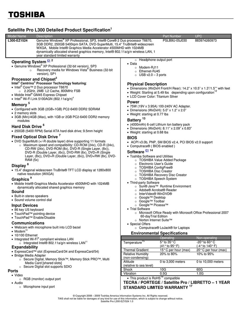
HP Armada 3500 Technical document
Other HP Laptop manuals
HP
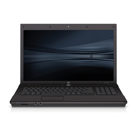
HP 4710s - ProBook - Core 2 Duo 2.53 GHz Manual

HP
HP 15-cc000 Manual
HP
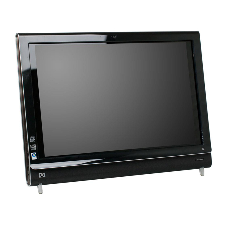
HP TouchSmart IQ810 Assembly instructions

HP
HP EliteBook 830 G6 Assembly instructions

HP
HP 2133 Mini-Note User manual
HP
HP Notebook User manual
HP
HP Pavilion HDX Entertainment Series Manual

HP
HP Compaq Presario User manual

HP
HP Dv5-1010us - Pavilion - Core 2 Duo GHz User manual

HP
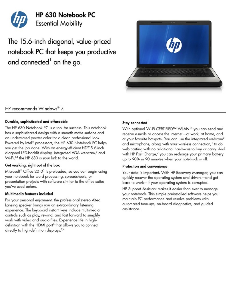
HP PRESARIO CQ61-424ER User manual
HP
HP Officejet 630 User manual

HP
HP Pavilion XT276 Specification sheet

HP
HP Compaq NC6140 Installation instructions

HP
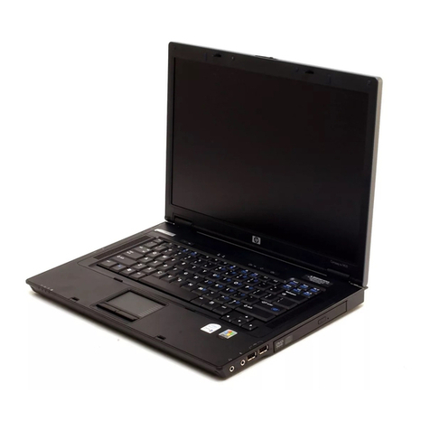
HP TBD Manual
HP
HP Compaq NX7300 Manual

HP
HP Pavilion Gaming Assembly instructions

HP
HP Compaq Presario CQ71 Manual
HP
HP VH677UA#ABA - Pavilion Dv6-1244sb... User manual

HP
HP VH677UA#ABA - Pavilion Dv6-1244sb... User manual

HP
HP 2230s - Compaq Business Notebook Installation instructions

