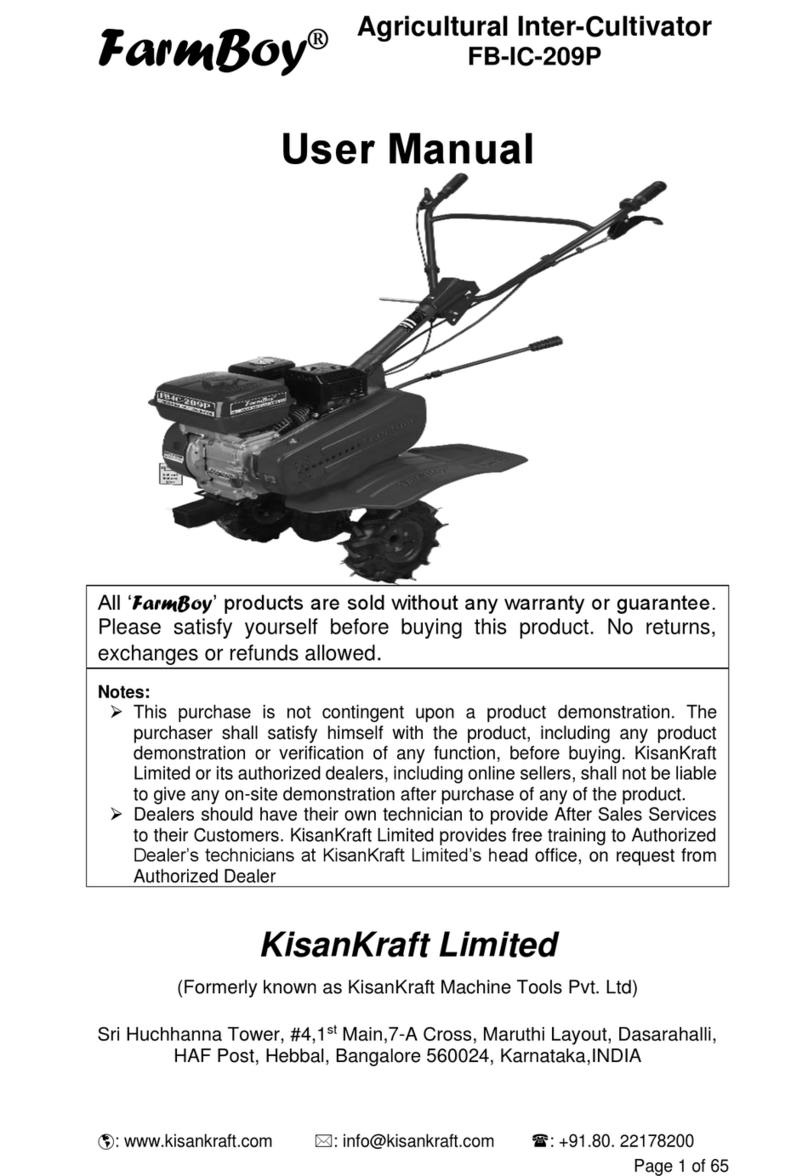
HPG GT1050B User manual

Manual of Gasoline Tiller
GT1050B

Warning
This manual is one of the important random documents of micro-tillage machine.
If the micro-tillage machine is transferred, it should be transferred together.
Please read this manual carefully before use, and strictly follow the instructions
for operation, micro-tillage machine is safe, if not according to the provisions of the
operation, light will cause damage to micro-tillage machine, heavy will occur personal
injury and death accidents.
In case of any abnormality or malfunction of the machine, the user shall
immediately stop using the machine and contact the local after-sales maintenance
department or personnel of our company for repair. Use or operation with malfunction
is strictly prohibited. If you have any questions about the machine, please consult our
local distributor or our head office.
This machine should use the specified fuel, do not add wrong fuel!
This machine is only suitable for the rotary tillage of relatively flat, mature fields,
and dry lands. It is strictly prohibited to exceed the scope of use and change its use!
It is strictly prohibited to add the tractor to the machine for transportation,
otherwise the accident will occur and the responsibility will be borne by the owner!!!
Chapter One Safe handling specification
2.1:Training
A) carefully read the operation and maintenance manual. A thorough
knowledge of all operating mechanisms and proper use of machinery. Master how to
stop and quickly separate the operating mechanism.
B) Children should never be allowed to use machines. Never allow an adult to
use a machine without reading instructions.
C) Keep the work area free of people, especially children and pets.
2.2:Prepare
A) Thoroughly inspect the area to be used by the machine and remove all
sundries.
B) Disengage all clutches and put them in neutral before starting the engine
(motor).
C) Do not operate the machine without a proper coat. Wearing antiskid shoes
will improve stability on slippery surfaces.
D) Handle fuel with care; it is flammable.
a) Use appropriate containers to store fuel.
b) Do not put oil into the tank while the engine is running or heating.
c) Take special care to fill the tank outdoors. Do not fill the tank indoors.
d) Before starting, tighten the oil tank cap and wipe off the spilled fuel.
E)No adjustment shall be made while the engine (motor) is in operation (except

the special adjustment recommended by the manufacturer).
F)Safety glasses should be worn during any operation such as preparation,
operation and maintenance.
2.3:Operation
A)hands and feet must not be close to or under rotating parts.
B)Special care should be taken when operating on (or through) gravel pavements,
pavements or highways to guard against potential dangers, pay attention to traffic
conditions and do not carry passengers.
C)After hitting the sundries, stop the engine (motor) and check whether the
cultivator is damaged comprehensively. If damaged, the cultivator can only be restarted
and operated after repair.
D) Always watch your step to avoid slipping or falling.
E)Once abnormal vibration occurs, the machine should immediately stop the
engine (motor) to find the cause, vibration is usually the precursor of failure.
F)When leaving the control position, stop the engine (motor) before cleaning up
blade blockage and during maintenance, adjustment or inspection.
G) When the machine is unattended, all possible precautions should be taken:
disconnect the power output shaft, lower the attachment, stall the engine and remove
the switch key.
H) Before cleaning, repairing or inspecting the machine, the engine should be
turned off and all moving parts should be in a stop state.
I) Exhaust fumes from the engine are harmful. Do not operate indoors.
J) No tillage machine shall be operated without proper protective device,
protective cover or other protective device in place.
K) Stay away from children and pets.
L)Do not overload the machine due to the high depth and speed of ploughing.
M) The machine must not run at high speed on slippery roads. Observe the back
and operate carefully when going backwards.
N) No bystanders are allowed to approach the machine while it is in operation.
O) Only additional devices and equipment (such as wheel weights, balancing
blocks, cab, etc.) permitted by the tiller manufacturer shall be used.
P)Do not operate the cultivator when vision or light is poor.
Q) Care should be taken when tilling hard ground. Blades may hook into the
ground and push the tiller forward. If this happens, release the handrail and do not
control the machine.
R) Cultivators are not allowed to work on steep slopes.
S)Tilting should be prevented when the cultivator goes downhill.
2.4:Maintenance and storage
A) Keep machines, accessories and equipment, including batteries, in safe
working condition. If possible, remove the battery for storage to prevent freezing and
charge properly if necessary.
B) Check whether the shear bolts, engine fixing bolts and other bolts are
tightened properly at regular intervals to ensure that the machine is in a safe working
state.

C) The machine should be stored indoors and away from the source of fire. The
engine should be cooled before the machine is stored indoors.
D) If the cultivator is to be stored for a long time, the operation manual should
always be kept as important data.
Chapter Two safe operation rules
A、machine conditions
a) The safety device of micro-tillage machine should be complete and the function
should be normal.
b) No illegally assembled or modified micro-tillers shall be used.
B、Personnel conditions
a) Operators should be trained in safe operation and master safe operation skills.
b) Operators with long hair should braid and wear work caps
c) When operating the micro-tillage machine, the operator should tie up the
clothes, cuffs and trousers to avoid being entangled.
d) No person may operate a micro-tillage machine under any of the following
circumstances:
-Suffering from diseases that impede safe operation;
-Drinking alcohol or using psychotropic drugs or narcotic drugs under state
control;
-Pregnant women, minors and people who do not have full capacity to act.
C、service conditions
a) The distance between the micro-cultivator and the non-operator shall not be less
than 5m.
b) Field operation direction slope should be not more than 5 °
c) The surface of the field should be flat and the cultivated layer should be free
from stones, sundries and so on.
d) Greenhouses and solar greenhouses should be well ventilated.
e) Vision should be good.
D、Start
a) According to the safety requirements of the operation manual, check and
confirm that all parts are in good safety and technical condition.
b) Before starting, the transmission lever should be in neutral position, the power
transmission between the engine and the transmission box should be in a separate state,
and the throttle switch should be in the starting position.
c) Before starting the operation, the operator should correctly install the plough
knife, resistance bar and other working parts, and confirm their effectiveness.
d) Operator's body should avoid contact with rotating, moving, high temperature
and other dangerous parts.
E、Starting
a) Air operation shall be carried out according to the requirements of the operation

manual before starting, and start after confirming safety.
b) The oil door, clutch and other parts of the micro-tillage machine are flexible
and reliable. The rotating parts have no lag in rotation and the automatic return handle
is in normal position before starting.
c) The automatic stop device of the blade shall not be controlled by means other
than manual control.
d) Micro-tillage machine with steering mechanism, the right and left steering
clutch should be in a combined state.
F、field operation
a) When slope work, should work along the slope direction.
b) Before using reverse gear, stop the machine to remove the resistance bar, and
operate carefully after confirming safety.
c) Turn off the engine before removing dirt, weeds, and other debris from the blade.
d) When the ploughing knife falls into the soil and cannot advance, the engine
should be shut down and handled by human.
e) When the operator leaves the operating position, shut down the engine and
remove the switch key.
f) The operator must not operate fatigue, the engine should be shut down at rest.
g) When replacing the operator in operation, the shift lever should be placed in
neutral to ensure that the power transmission between the engine and the gearbox is in
a state of separation.
G、Transfer
a) The engine should be shut down before transfer and the walking wheel should
be replaced.
b) If the ridge height or the width and depth of the ditch are greater than the
maximum turning radius of the plough blade, the engine should be shut down and
transported manually.
c) When moving through the road, should comply with road traffic safety
regulations, and keep a safe distance from other vehicles and pedestrians.
d) No person or object may be carried on the micro-tillage machine.
H、Stop check
a) When one of the following situations is encountered in the operation of micro-
tillage machine, it shall stop the machine immediately for inspection:
-Ploughing knife wrapped grass, sticky mud serious;
-Abnormal sound of engine or transmission box;
-Abnormal increase of engine speed, throttle control failure;
-Other abnormal conditions.
Chapter Three Safety warning sign

regulations
when the machine is
running.
No overspeed operation
A、The position and quantity pasted on the machine
Attached to the handrail rail, Quantity 1 sheet/setAffixed near the engine muffler, Quantity 1 sheet/set
Against the windshield of the engine,Quantity 1 sheet/setAttached to the engine tank,Quantity 1 sheet/set
On the fender,Quantity 1 sheet/setOn the fender,Quantity 1 sheet/setOn the fender,Quantity 1 sheet/set
On the fender,Quantity 1 sheet/setOn the fender,Quantity 1 sheet/set
Chapter Four main technical parameters
the
blade is in
operation

Executive Standard:JB/T 10266-2013
Sequence
number
Items
Units
Specification
one
Specifications and models
/
1WG 4.0-105FQ-ZC
two
Auxiliary
engine
Rated power
kW
5.0
Rated Speed
r/min
3600
type
/
Single cylinder, air-cooled
gasoline engine
three
Working condition dimensions (length *
width * height)
mm
1630*1050*920
four
working width
mm
1050-1400
five
Kind of drive
Engine output
/
Direct connection
Knife roll
Gear drive
six
Handle
adjustment
Horizontal direction
(°)
0
Vertical direction
107
seven
Rotary blade model
Dryland knife
eight
Maximum radius of rotation of cutter
shaft
mm
180
nine
Total number of mounting knives
/
32
ten
Main clutch
type
Type
/
Friction plate
Status
Normally open

Chapter Five Form a complete set of requirements
Supporting power type、Designation:
1WG4.0-70FQ-ZC、1WG 4.0-105FQ-ZC、CB engine The engine of type v micro
- plough is air - cooled gasoline engine.
B、Supporting engine form and model:
Engine brand and model:1WG4.0-70FQ-ZC、1WG 4.0-105FQ-ZC、CB
enginetype I micro-tillage machine is 170F/P gasoline engine.
C、Requirements for supporting ploughing knife:
1WG4.0-70FQ-ZC The width of the design blade of type I micro-tiller is
all:700mm,1WG 4.0-105FQ-ZC、CB engine the width of the design blade of type I
micro-tiller is all:1050mm.
The standard configuration of ploughing knife is:Dry land ploughing knife, user
selection with ploughing knife, should be selected with the original factory ploughing
knife.
When the user needs to replace the engine, at least the engine of the same
type, power, speed, purpose and so on should be replaced, otherwise it cannot
match, and even cause damage to the machine and accidents.
If not according to the original factory design requirements supporting
power, plow knife, walking wheel, and change the original factory supporting
requirements, beyond the scope of use, machine damage and human injury and
death accidents will occur.
Chapter Six Installation method
A、Assembly after unpacking:
a)Fix the host and insert the hexagonal output shaft shaft into the hexagonal hole
of the output shaft sleeve at the lower part of the walking box assembly.
b)Use M6 * 16 hexagon socket screws to set the hexagon limit set on the
hexagon output shaft, so that the hexagon output shaft cannot move in the axial
direction.
c)Put the wheel:Install the wheels on both ends of the hexagonal output
shaft,And with two M8 * 55 bolts,M8 nut fixed.
d)Assembly of towing device:Insert drag rod box assembly in drag rod bearing
seat, with resistance rods inserted pin connection box and insert Φ 3*26, insert drag rod
inserted into the box slot, and load resistance with M8*55 after stick pin bolt, nut
positioning.
e)Installation of handrails:Put the two tooth discs on the support seat in the
positive direction, and pay attention to adjust the upper and lower positions of the
direction knob, which is attached with M16 * 140 bolts, plain pad 16, spring pad 16,
handle assembly connection and locking.

f)Assembly of joystick:Will shift lever from the direction of bearing seat through
the slot of shifting support block, inserted into a slot in the shift arm, with a split pin Φ
3.2 x 16 fixed.
g)Put the shift lever in "neutral" position.
B、Installation and adjustment of cables:
a)Adjust throttle cable. (see figure 1 and figure 2)
①Put the throttle switch in the largest position.
②Pass the wire rope in the throttle cord through the threaded column and
retaining seat above the engine throttle adjustment plate.
③Tighten the wire rope, tighten the fastening screw on the fixing seat.
b)Adjustment of clutch stay wire (see figure 1 and figure 2)
①Loosen the lock nut on the screw.
②Turn the screw clockwise to expose the armrest frame to the shortest.
③The cable head into the lower end of the handrail seat clutch line seat, and
ensure that the cable through the hole in the line seat.
④The appropriate pressure clutch arm, the wire rope from the M8 screw hole
through and nut lock.
⑤Turn out the screw and repeatedly hold, release the clutch handle to the spring
force in the clutch can return the backhand, tighten the lock nut.
c)Adjustment of reversing stay wire (see figure 2)
①Loosen the lock nut on the screw.
②clockwise rotation of the screw to the exposed direction to the shortest.
③pull the cable into the main gear box side of the reverse shift fork shaft and
ensure that the cable head into the fork shaft hole.
④the appropriate counterclockwise pull shift fork shaft, pull the cable through
the main gearbox side of the shift line seat through the narrow seam, and ensure that
the pipe head into the line seat hole.
⑤Turn out the screw and hold it repeatedly, loosen the reversing handle, and
tighten the lock nut when the spring force can reset the handle.
Clutch Cable
Clutch line a
Clutch fork shaft assembly
Reverse thread
Wire connector
Reverse shift fork shaft
C、Inspection and refueling
a) Check engine oil:
Place the engine in a horizontal position, remove the oil gauge and wipe off the
oil film. Then put the oil ruler into the oil injection hole (do not tighten), then take out
the oil ruler to observe the oil level

◆If the oil level of the gasoline engine is close to the lower part of the oil ruler,
clean oil for the gasoline engine should be added to the neck of the oil injection hole.
◆The oil of a gasoline engine is not interchangeable with that of a diesel engine
Warning!
◆Engine oil should be added to the specified position according to the
requirements of its instructions. If the oil level of the engine is lower than the normal
state, the use of the engine will cause serious damage to the engine!
◆Please use clean, high quality four stroke engine oil. If the use of dirty oil or
other brand of oil will shorten the service life of the engine.
b) Check each handle of the control system:Whether the action of (throttle, shift
lever) is flexible and all situations in place should be excluded. Check whether the
connecting bolts and nuts are loose and tighten as required.
c) Add oil:
①The special lubricating oil for gasoline engine must be used in the box of
gasoline engine whose brand is CC grade or above。
②Add no. 20 lubricating oil into the transmission box, level the whole machine,
and inject it into the oil hole above the transmission box. When checking the oil level,
insert the oil ruler (note: do not rotate the oil ruler), and the oil level should be between
the upper and lower limit of the oil ruler. (see figure below)
Cograph:oil level gauge Cograph:Engine oil check
d) Refuel:
Add the specified brand of fuel oil and fill the gasoline tank with gasoline no. 92
e) Check the empty filter:
Remove the air filter cover, remove dust and add proper oil. (note: just keep the
oil on the bottom)

Chapter Seven Operating instructions
Warning!
1、It is forbidden to run the engine without air filter. Oil with upper and
lower cutting lines should be added into the filter, otherwise the engine will wear
out faster.
2、Before starting the engine, the shift lever must be placed in neutral
position and the clutch handle is separated! Otherwise there will be casualties or
property damage accidents!!
3、In case of emergency, the engine should be quickly shut down and the
clutch handle released!
4、The microtiller must be run in before operation.
5、Do not suddenly release the starter handle to allow it to rebound and
damage the engine, should be slowly followed by the starter pull rope back to the
spring.
6、In the process of use, attention should be paid to the working condition
and sound of each part. Check whether the connection of each part is normal and
no looseness is allowed. If any abnormality is found, stop the machine to check
and eliminate it.
7、It is not allowed to start the cold car immediately after heavy load work,
especially the new machine or overhaul of the machine.
8、Pay attention to check the oil level of engine and transmission box.
9、Do not cool the engine with water.
10、The toppling of microtiller should be prevented during tillage.
11、It is strictly prohibited to install a rotary blade on the micro plow in the
sand or gravel pile driving, so as not to damage the blade.
12、After the use of farming, attention should be paid to remove soil, weeds,
oil stains attached to the micro-tillage machine, keep the machine clean.
13、Always clean the spongy body in the filter.
A、Start (note: shift lever must be in the middle neutral position)
a)Start the diesel engine according to the steps specified in the diesel engine operating
instructions.
b)The diesel engine should run for 2 ~ 3 minutes without load at idle speed (1500 ~
2000 RPM).
c)Check whether the diesel engine is running normally, if not, stop the diesel engine
for maintenance.
B、Operation
Note: throttle cable adjustment is not good, will affect the normal use of the
product.
a)Hung low gear
①Press the throttle handle with your right hand, use the throttle in the minimum
position, and the engine is running at idle speed.
②In the neutral position, pull back the operating lever with your right hand,

and pay attention to whether you feel it in place, then hold the right handrail with your
right hand.
③The right hand should appropriately increase the throttle, speed up the
operation, grasp the clutch handle, clutch joint, micro-tillage machine is running at a
slow speed of about 5km/h.
b)gear up
①Press the throttle handle with your right hand, use the throttle in the minimum
position, the engine is running at idle speed, the automatic clutch will automatically
separate.
②Push the lever forward in neutral position with your right hand. And pay
attention to whether the feeling is in place, and then hold the right hand handrail.
③The right hand is appropriate to increase the throttle, speed up the operation,
automatic clutch joint, micro-tillage machine is running at the speed of fast gear.
c)Selecting reverse
①Press the throttle handle with your right hand, use the throttle in the minimum
position, the engine is running at idle speed, the automatic clutch will automatically
separate.
②Pull the lever to the middle neutral position with your right hand, and pay
attention to whether you feel it in place, then slowly grasp the reverse handle with your
left hand.
③The right hand appropriately increases the throttle, speed up the operation,
automatic clutch engagement, micro plow back.
(note: do not release the reverse handle)
④When you don't need to back up. Press the throttle handle with the right hand,
use the throttle in the minimum position, release the reverse handle with the left hand,
and the reverse gear is pulled out of engagement by the spring force.
d)In the process of shifting gear, the engine throttle should be reduced first, (the
engine does not go out) automatic clutch automatic separation, when the machine will
stop walking, then shift gear.
e)Turn, turn left or right by pulling the handrail.
(note: do not grasp the wrong handle of steering to avoid damaging the gear)
f) Parking
①The right hand moves the throttle handle to keep the throttle in the minimum
position. The engine operates at idle speed, the automatic clutch is in the state of
automatic separation, and the machine stops running.
②When the engine needs to stop, should follow the engine operating
instructions related content.
(note that micro-tillers usually stop on flat land)
g)emergency cut-off
①During farming, when the throttle is in the minimum position, the clutch fails
to disengage (due to clutch failure) and the machine cannot be stopped. Emergency
parking is required at this time.
②The left hand moves the pressure relief handle switch to make it in the
maximum state. The pressure-reducing valve at the engine is opened under the action

of the tension bar line, and the engine combustion chamber is free of pressure and
automatically stops and shuts down.
C、Connection and use of supporting machines and tools
a) When rotary tillage is needed, remove the wheels, put the hexagon pipe sleeve
of rotary tillage device at both ends of the driving shaft of the walking mechanism, and
fix it axially with a small pin shaft. Note: rotary tillage is divided into left and right
knife groups, and the blade edge should work first when the micro-tillage machine
moves forward after installation. After the rotary plough knife is installed, the left and
right fenders must be installed to avoid injury caused by rotary plough. The depth of
rotary tillage can be achieved by adjusting the height of resistance bars and the Angle
between them on the ground (see the following table).
Rate of travel
Working depth
Fast
Below 150 mm
Centre
Between
150 and 250 mm
Slow
Above 250mm
Droughtharde
ns the soil
The Angle between
the resistance bar and
the ground
15°
45°
90°
165°
cutline
D、Precautions for the use of microtiller
a) In the process of use, attention should be paid to the working condition and
sound of each part. Check whether the connection of each part is normal and no
looseness is allowed. If any abnormality is found, stop the machine to check and
eliminate it.
b) It is not allowed to start the cold car immediately after heavy load work,
especially the new machine or overhaul of the machine.
c) Pay attention to check the oil level of the engine and gearbox.
d) Do not cool the engine with water.
e) The toppling of microtiller should be prevented during tillage.
f)It is strictly prohibited to install the micro-tilter with rotary blade to exercise on the
sand beach or gravel pile, so as not to damage the blade
g) After the use of farming, attention should be paid to remove soil, weeds, oil
stains attached to the micro-tillage machine, keep the machine clean.
h) Clean the sponge in the filter regularly and change the oil.
Chapter Eight Maintenance
During the working period of micro-tillage machine, due to the operation, friction
and wear and load changes, it is inevitable to produce the phenomenon of loose
connection bolts and wear of parts, so that the correct state of the system is damaged,
resulting in abnormal fit clearance and engine power drop. The increase of oil
consumption, the maladjustment of various components, the increase of micro-tillage
machine faults, seriously affect the use of micro-tillage machine. To reduce the
occurrence of afore - mentioned circumstance, must be done strictly, regularly with

"precaution is given priority to" maintain work. In order to maintain a good technical
record of micro-tillage machine and extend its service life.
A、Running
a) Please refer to the operation manual for engine run-in.
b) The new or overhaul of the micro-tillage machine, should first work in no-load
conditions for l hours, in light load conditions for 5 hours immediately after the heat
release of the transmission and engine crankcase all lubricating oil. Inject proper
amount of clean diesel oil, run at low speed for 3-5 minutes with slow speed to clean,
and then drain the diesel oil.
Then according to the sixth chapter \ three \ (4) procedure to inject oil for 4 hours
run-in, your micro-tillage machine can be put into normal farming.
B、Technical maintenance of micro-tillage machine
a) Maintenance per shift (before and after work of each shift)
1、Listen and observe for anomalies (abnormal noise, overheating, screw
loosening, etc.).
2、Check engine, gearbox and transmission box for leakage.
3、Check whether the oil level of engine and gearbox is on or off the oil scale.
4、Timely remove dirt, weeds and oil stains on the whole machine and
accessories.
5、Fill in the farming record.
b) Primary maintenance (150 hours per work)
1、Carry out all the maintenance of each shift.
2、Clean gearbox and travel box and change oil.
3、Check and debug clutch, shift system and reverse system.
c) Secondary maintenance (800 hours per work)
1、Carry out all maintenance contents for every 150 hours of work.
2、Check all gears and bearings. Replace with new parts if wear is serious.
3、Other parts of the micro-cultivator, such as rotary blade or connecting bolt,
etc., should be damaged, please replace with a new one.
d) Technical maintenance (1500-2000 hours per work)
1、Go to the local special maintenance station to disassemble, clean and inspect
the whole machine. Wear and tear parts must be replaced or repaired as appropriate.
2、Professional maintenance personnel should check the wear plate and clutch.
e) Maintenance of diesel engine. Please follow the instruction of diesel engine.
C、Technical maintenance table of micro-tillage machine (the square root is marked
in the table to indicate the maintenance content that should be done)
•working gaps
Maintenance of content
days
Work eight hours
under half load
After the first month
or 20 hours
The third month
or 150 hours
later
Every year or
1,000 hours
later
In year two
or two
thousand
hours
Check and tighten nuts and
bolts
√
Check and refuel engine oil
√
Clean and replace oil
√(the first time)
√(the second time)
√(third and
subsequent)
Check for oil leakage
√

Remove dirt, weeds, oil and
keep it clean
√
Trouble shooting
√
Adjusting control unit
√
clutch friction plate
√
Gears and bearings
√
D、Long-term storage of micro-tillers
In order to prevent corrosion, the following measures should be taken when the micro-
cultivator needs to be stored for a long time.
a) Seal up diesel engine according to engine operation instruction.
b) Clean appearance of dust, dirt.
c) Release the lubricating oil from the transmission and inject new oil.
d) Apply anti-rust oil where the surface of non-aluminum alloy is not painted.
e) Store the machine in a ventilated, dry and safe place indoors.
f)Take good care of random tools, product qualification certificate and instruction
manual.
Chapter Nine Debugging methods and data
A、Debugging method and data of bevel gear pair:
When it is confirmed that the bevel gear pair transmission is abnormal or abnormal
sound is too large, it is necessary to check and debug, the method is as follows:
a) Adjust clearance of bevel gears in gearbox. (see figure 10)
①When gear pair backlash train < 0.15, that should be between the gearbox
and transmission box increase 0.1-0.5 steel-paper cushion to increase the backlash.
②When the gear pair clearance delta > 0.5, which should be between the
bearing and gear Ⅱ mat 0.1 0.5 pads to reduce lateral clearance. At the same time
guarantee the gear Ⅱ axial clearance, 0.3 t-0.5.
b) Clearance debugging of bevel gears in the transmission box (see figure 11)
①When the gear pair clearance delta < 0.15, which should increase adjusting
pad I (0.2-0.3) to increase the lateral clearance, and change the vulcanized fiber mat
mat Ⅲ Ⅱ and adjusted to guarantee gear Ⅱ axial clearance 0. 3-0.5。
②When the gear pair clearance delta > 0.3, which should reduce adjust pad I,
at the same time guarantee the gear Ⅱ 0.05 0.15 or increase axial clearance adjustment
mat Ⅱ, at the same time ensure gear axial clearance, 0.05 - 0.015。
B、Debugging method and data of reverse gear and cable
When it is confirmed that it is not normal for the micro-cultivator to move backward,
it is necessary to adjust the handlebar and tie wire in reverse gear. Refer to chapter 6
for the method.
Note: 1、Hold and release the reverser for 2-3 times to confirm the reverser.If it is
abnormal, it should be readjusted until qualified.
2、When the micro-tillage machine is running, loosen the reverser handle, the
reverser gear should be returned to its position, and there should be no abnormal
sound of gear collision in the gearbox, otherwise the gear will be damaged.
C、Debugging method and data of accelerator and tension wire

When you turn the throttle switch. Engine acceleration or deceleration
performance is poor, that is to say, the throttle tension line should be adjusted. Methods
refer to chapter 6.
Note: 1、 Repeatedly turn the throttle switch 2-3 times and confirm the acceleration
and deceleration performance of the engine。
2、Throttle pull wire and pull wire joint must be firmly connected with screws.
D、The debugging method of handrail frame
According to your height and farming agronomy and other special requirements,
the armrest frame, under the appropriate debugging, the method is as follows:
Handrail frame and lower debugging:、
①Release the locking handle of the armrest frame and let the end teeth between
the armrest frame and the teeth of the grinding disc be separated.
②Choose the handle position according to your height and habit.
③Then turn the handle so that the end teeth between the rack and the support
arm mesh.
High and low hands
High and low adjusting handle
Handrail support pedestal
Chapter Ten Common faults and fix methods
A、See engine manual for engine failure and troubleshooting methods.
B、Clutch failure and troubleshooting.(note: please do not disassemble the clutch
assembly by yourself. Note: please contact our company or the seller for the
malfunction of ※.)
Phenomeno
n
Cause
Elimination methods
Can't clutch
Clutch handle failed
Repair or replace
Clutch tension bars are linearly damaged
replace
Clutch fork adjustment is not in place
Rewire or replace the fork
The welding joint of clutch and fork shaft
combination falls off
Repair or replace
To bend or break a fork pin
Replace the fork pin
※The friction disc fails
replace
※failure of spring
replace

C、Transmission malfunction and troubleshooting
Phenomenon
Cause
Elimination methods
Fast, slow, not in
place
The back bolt of the spindle is loose and the
round nut is loose
Remove the back of the spindle bolts,
key sleeve, locking circular nut after
the key sleeve, bolt and tighten
The gear is not in
position
The drawing block wears out too much
Replace the pull block
Auxiliary shaft loose
Tighten the rear bolts of the auxiliary
shaft
The upper hole of the connecting block of the
straight arm is worn too much
Replace arm assembly
Spindle internal positioning spring failure
change
Spindle movement: the back of the box gland
screw is loose
tighten screw
Shift rod deformation causes shift interference
Correct shift lever or replace
The reverse gear is
not in place
Reverse shift fork wear
Readjust the rewind cable and replace
the rewind fork
Reverse pull wire failed
Reset the stay wire and replace the
stay wire
The reverse shaft is loose
Tighten the rear bolt of the reverse
shaft
The reverse gear is stuck
Clean up the joint surface of reversing
fork shaft and steel sleeve to make it
rotate flexibly
Reverse gear does
not return
Excessive wear of gear bushing
Replace the village set
Loose reverser shaft causes gear hairpin
Tighten the rear bolt of the reverse
shaft
Spring failure on reverse shaft
Replacement springs
Reverse shaft bending deformation
Replace the reverse shaft
The reverse shaft is
loose
The back bolt of the reverse shaft is loose
Tighten the back bolt of the reverse
shaft
The reverse shaft is too loose with the box
body
change
Auxiliary shaft
loose
The bolt at the back of the auxiliary shaft is
loose
tighten the bolt
The auxiliary shaft is too loose with the box
body
change
Excessive gear
noise
Auxiliary shaft, reverse shaft loose
Tighten the rear bolt of the reverse
shaft of the auxiliary shaft
Auxiliary shaft, reverse shaft deformation,
bending
change
Excessive wear of gears with excessive
clearance
Replace sprocket
Auxiliary shaft, reverse shaft and box body
are too loose
change
Oil leakage from the
back cover of the
spindle
Failure of O-ring on spindle
Replace the o-ring Ф 17 x 1.8
Spindle upper lip oil seal failed
Replace lip failure oil seal B25 * 40 *
7
Failure of O-ring on gland
Replace the o-ring Ф 42.3 x 2.4
Oil leakage from
reversing shaft
The bolt at the back of the reverse shaft is
loose
Tighten the reverse shaft bolts
Reverse shaft O- ring failure
Replace the o-ring Ф 18 x 1.8
The friction disc group shall not touch the
bearing end face in the clutch housing
Add proper adjusting pad after
bearing
The inner bearing of the ejector is burnt out
Replace the gearbox with oil
Skidding
※Spring fatigue failure
replace
Clutch fork shaft combination transfer
failure makes fork is not fully reset
Clean the combination surface of fork
shaft and movable pressure plate to
make it turn flexibly
Improper alignment of clutch tension bars
Readjust the clutch tension line

Reverse shift fork
shaft leaking oil
O ring failure
Replace the o-ring Ф 11.2 x 2.65
The clutch fork shaft
leaks oil
O ring failure
Replace the o-ring Ф 11.2 x 2.65
Oil leakage at shift
shaft
O ring failure
Replace the o-ring Ф 11.2 x 2.65
Leaking oil at the
liner joint
The bolt is loose at this point
Tighten the bolts at this point
The steel paper pad is damaged there
change
Casing leakage
The box body is provided with hidden micro
porous holes
Repair welding or primer nagisa
leakage
D、Malfunction and troubleshooting of walking mechanis
E、Other faults and troubleshooting
Phenomenon
Cause
Elimination methods
Interrupted by a
rotary blade
The use of stones, bricks and other
hard objects
change,Pay attention to avoid collision
with hard objects such as stones in the soil
Control cable broken
Long service wear
change
Chapter Eleven Range of application
This machine is suitable for many kinds of farming projects, such as flat dam,
hilly, mountainous area dry land, tea garden, orchard, flower and vegetable
greenhouses, etc.
Phenomenon
Cause
Elimination methods
Excessive gear
noise
Excessive wear and tear or improper repair of
gears
Reassemble and adjust or replace gears
Gear transfer card
Incorrect assembly
reassemble
Less lubrication inside the box
Add oil as required
Excessive heat
The gear side clearance is too small
reassemble
The axial clearance is too small
reassemble
Oil leaking from
the transmission
connection
The connection bolt is loose at this point
tighten the bolt
The gasket is damaged at this point
change
The outer circular
surface of the
output shaft
bushing leaks oil
The lip - shaped oil seal pad is damaged
Replace lip oil seal B45 * 62 * 8
The leakage of
hexagonal hole in
output shaft
bushing is serious
The shaft sleeve is broken
change
Oil leakage occurs
at the drain hole
The o-ring is damaged at this point
Replace the o-ring Ф 10 x 1.8
Screw loose
Tighten as required
Casing leakage
The box body has concealed micro - porous
holes
Repair welding or primer leakage

Chapter Twelve Structural schematic diagram and circuit
1、The clutch handle 2、arm-rest frame 3、shift level 4、clamp handle
5、engine 6、Drag bar 7、fender 8、bumper 9、road wheel
Chapter Thirteen list of attachments
A、Factory standard configuration list
Micro-tillage machine a complete machine, dry land knife a pair, paddy field knife a pair, a set of random documents, random tools a set.
B、Shopping list
Sequence
number
designation
unit
use
one
Paddy field rotary tillage
device
cover
underwater cultivation
two
Ditches and ridges
cover
Ditches and ridges
three
Deep knife
cover
Open wasteland, and harder soil
four
Anti-tangling blade for
grass ploughing
cover
Drought, wasteland and grass
weeding and arable land
five
compound cutter
cover
Drought, wasteland and grass
weeding and arable land
Chapter Fourteen Wearing parts list
Sequence
number
designation
•Which parts
one
Pressure relief handle cable
The handle assembly
two
Pressure relief handle switch
The handle assembly
three
Reverse gear guy
The handle assembly
four
cable accelerator
The handle assembly
five
throttle cock
The handle assembly
six
Big rubber sleeve
The handle assembly
seven
Small rubber sleeve
Shift lever and lock handle
eight
Frame oil seal 25* 47 * 8
Transmission box assembly
nine
Frame oil seal 25 x 35 x 7
transmission assembly
ten
Inside and outside the tire
/
eleven
All kinds of farming tools
/

twelve
Engine wearing parts
Refer to engine manual and atlas
Table of contents
Popular Tiller manuals by other brands

Toro
Toro 09802 HydroJect 3010 Operator's manual

SNOWJOE
SNOWJOE Sunjoe 24V-X2-TLR14 Operator's manual

Troy-Bilt
Troy-Bilt OEM-290-264 Installation and use instructions

Einhell Royal
Einhell Royal EBH 750 Original operating instructions

Craftsman
Craftsman 917.293311 owner's manual

Maxim
Maxim MT PRO Series owner's manual