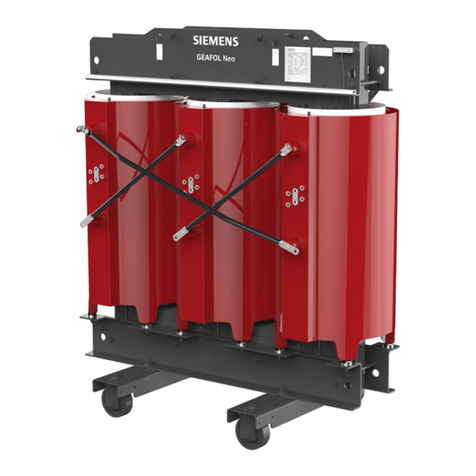
HPS Titan N Series Technical Document

Disclaimer of Liability
The recommended practices in this manual are for general applications and are supplied without liability for errors or
omissions. Technical data are subject to change at any time without notice and any necessary corrections will be included
in subsequent editions.
Special requirements should be referenced back to the manufacturer and/or their representative.
*Note: this guide is Trilingual
(English, French, Spanish)
The pictures used in this guide are only a representation and may vary from the actual product.
Page
Warnings 2
Safety Instructions 3
General 4
Handling 4
Receiving & Inspection 4
Storage 5
Installation 5
Ventilation 6
Accessibility 6
Transformer Sound Levels 6
Cable Connections 7
Grounding 8
Altering the Transformer 8
Before Energization 9
Operation 9
Maintenance 10
Dry-out of Transformers 11
Accessories 12
Literature No.: TIT3IM
Issue Date: January 2019
This manual covers the recommendations for the installation,
operation and maintenance of three-phase encapsulated low
voltage transformers. It is emphasized that these abbreviated
instructions should be used in conjunction with all local and
National codes and should be referenced accordingly.
For indoor/outdoor three-phase
encapsulated transformers which utilize
DQT type enclosures.
Installation, Operation, and Maintenance Guide

2
Encapsulated Low Voltage Transformer
WARNINGS
This manual contains warnings to observe in order to ensure
personal safety and prevent property damage. Read these
instructions carefully and look at the equipment to become
familiar with the device before trying to install, operate, service
or maintain it. The notices referring to personal safety are
highlighted in the manual by a safety alert symbol, notices
referring only to property damage have no safety alert symbol.
These notices shown below are graded according to the degree
of danger. If more than one degree of danger is present, the
warning representing the highest degree of danger will be
used.
DANGER indicates an imminently hazardous
situation which, if not avoided, will result
in death or serious injury, and/or substantial
property damage.
DANGER
WARNING indicates a potentially hazardous
situation which, if not avoided, can result
in death or serious injury, and/or substantial
property damage.
WARNING
CAUTION indicates a potentially hazardous
situation which, if not avoided, can result
in minor or moderate injury and/or property
damage.
CAUTION
Important Note:
Electrical equipment should be installed, operated,
serviced, and maintained,only by qualified personnel.
No responsibility is assumed by the manufacturer
for any consequences arising out of the use of this
material.
This guide covers the recommendations for
the installation, operation and maintenance of
encapsulated dry-type transformers which utilize
DQT type enclosures. It is emphasized that these
abbreviated instructions should be used in conjunction
with all standards and local codes covering such work
and should be referenced accordingly.
These recommended practices are for general
applications and any special requirements should be
referenced back to the transformer manufacturer and/
or their representative.
It is further recommended that installation work
be governed by all applicable National, State and
Local codes standards and regulations and ANSI/IEEE
C57.94. This is the IEEE recommended practice for
Installation, Application, Operation and Maintenance
of Dry-type General Purpose Distribution and Power
Transformers. All work should be preformed in
accordance with NFPA 70E Standard for Electrical
Safety in the Workplace and CSA Z462, Workplace
Electrical Safety. Always use appropriate personal
protective equipment (PPE).

3
TIT3IM / January 2019
1. Do not lift or move a transformer without proper
equipment and properly trained personnel. Ensure that
the transformer is only lifted using the listing provisions
provided. Always use lifting provisions provided by the
manufacturer. Rolling and skidding are recommended only
on transformers with a pre-ordered skidding base.
2. Do not off-load the transformer until it has been fully
inspected for damages. If any damages are identified the
transformer should not be energized and the transformer
manufacturer should be contacted immediately.
3. Only use terminals for electrical connections. The
transformer terminals are not designed to support the
weight of line or load cable.
4. Connections should only be made in accordance with
the nameplate diagram or connection drawings and the
applicable local codes and standards.
5. Make sure all power (including back-fed control and
possible capacitor charge) is disconnected and all windings
are grounded before attempting any work on the
transformer or inside the enclosure. (zero energy)
6. Make certain all ground connections, line terminals and
selected tap connections are completed and tightened
before energizing the transformer.
7. Do not attempt to change any primary or secondary
connections or taps while the transformer is energized.
8. Do not tamper with control panels, alarms, interlocks, or
control circuits if provided.
9. Do not adjust or remove any accessories or cover plates
while the transformer is energized.
10. No cables should come in contact with or any live parts
except the terminal that it is intended for. Ensure that
minimum clearances are maintained at all times.
11. This equipment must only be installed and serviced by
qualified electrical personnel.
12. Follow all requirements in NFPA 70E and CSA Z462 for safe
work practice and personal protective equipment (PPE).
13. Replace all devices, doors, and covers before turning on
power to this equipment.
14. Modifications of any kind to the equipment are not
permitted. Besides voiding the warranty such actions
may result in hazardous situations of which the person(s)
performing the modifications will be solely liable.
Safety Precautions
DANGER
SAFETY INSTRUCTIONS
HAZARD OF ELECTRIC SHOCK, EXPLOSION OR
ARC FLASH
Refer to nameplate for ratings and voltages.
This equipment must only be installed and serviced by
qualified electrical personnel.
Follow all requirements in NFPA 70E and CSA Z462 for
safe work practice and personal protective equipment
(PPE).
Turn off all power supplying this equipment before
working on or inside equipment.
Always use a properly rated voltage sensing device to
confirm power is off.
Replace all devices, doors, and covers before turning
on power to this equipment.
Failure to follow these instructions will result in
serious injury or death.
Class 1, Division 2,
Hazardous Location
Installation Requirements
If this unit is designed for use in Class 1, Division
2, Groups A, B, C & D hazardous locations then
also refer to notes below:
(1) Power, input and output (I/O) wiring must be in
accordance with Class 1, Division 2 wiring methods
as per Article 501-10 (b) of the National Electrical
Code.
(2) WARNING - EXPLOSION HAZARD - DO NOT DIS-
CONNECT EQUIPMENT WHILE THE CIRCUIT IS
LIVE OR UNLESS THE AREA IS KNOWN TO BE
FREE OF IGNITABLE CONCENTRATIONS.
(3) WARNING - EXPLOSION HAZARD - SUBSTITUTION
OF ANY COMPONENT MAY IMPAIR SUITABILITY
FOR CLASS I, DIVISION 2.
Please check resin level before drilling hole for conduit and site
conduit properly so it does not come in contact with resin.

4
Encapsulated Low Voltage Transformer
Three-phase encapsulated transformers are
manufactured to provide optimum performance for a lifetime
of uninterrupted service. Careful attention to the following
instructions is recommended for safe and reliable operation.
Installation, operation and maintenance of transformers
should be performed by authorized personnel, trained and
qualified in the installation, repair and maintenance of electrical
equipment.
As any other electrical equipment, transformers must
be installed according to the requirements of all applicable
national and local electrical codes. ANSI/IEEE C57-94 may
also be referred to for recommended installation, application,
operation and maintenance of three-phase encapsulated
transformers.
Transformers are palletized and can either be lifted via a
forklift truck or hoisted by the lifting lugs provided.
Appropriate lifting equipment should be used relative to
the size of each transformer. For safety purposes and to protect
the transformer, spreader bars are recommended.
No attempt should be made to lift or move a transformer
from any points on the unit other than those indicated. Refer
to page 17 (lifting brackets). Avoid subjecting transformer to
impact, jolting and other rough handling that may damage the
transformer.
Ensure the transformers are transported in upright
position - avoid tilting and tipping.
Immediately after receiving the transformer, it should be
inspected for any transit damage and for correctness against
the shipping documents.
The unit should be examined for any breaks in its
packaging, dented or damaged enclosures or missing parts
from the packing list.
If any damage is noted, a claim should be filed
immediately with the carrier and a second copy of all pertinent
information relative to the order and the circumstances
should be immediately communicated to the transformer
manufacturers local sales office.
General
Handling
Receiving & Inspection
WARNING
Failure to follow lifting procedures can result in
death, serious injury, or property damage.
DANGER
HAZARD OF ELECTRIC SHOCK, EXPLOSION OR
ARC FLASH
Refer to nameplate for ratings and voltages.
This equipment must only be installed and serviced by
qualified electrical personnel.
Follow all requirements in NFPA 70E and CSA Z462 for
safe work practice and personal protective equipment
(PPE).
Turn off all power supplying this equipment before
working on or inside equipment.
Always use a properly rated voltage sensing device to
confirm power is off.
Replace all devices, doors, and covers before turning
on power to this equipment.
Failure to follow these instructions will result in
death or serious injury.

5
TIT3IM / January 2019
If the examination of the unit takes place outdoors,
caution should be exercised to protect the unit against factors
that may present further damage.
Transformers that will not be immediately installed and
energized, should be stored in a clean dry environment away
from any environmental airborne contaminants. Transformers
should be stored in such a way not to represent any type of
hazard. Stacking transformers one on top of another without
proper shelving is not permitted.
It is recommended that transformers be stored in a
heated building with uniform temperature and adequate
air circulation to prevent condensation with the protective
plastic wrap still installed for long term storage. If storage in a
heated building is not possible, transformers must be properly
protected from contaminants and moisture preferably in a
non heated building. We recommend that electric heating
be installed inside the transformer to maintain a uniform
temperature above the ambient and to prevent condensation.
In extreme cases they may be stored in temperatures no lower
than -40°C (-40°F). Special care should be given to prevent
the formation of condensation inside the stored transformers.
Units that are to be energized after being stored at a low
temperature or after being stored for a long time must be
warmed to -25°C (-13°F) with warm air or radiant heat. Once
the unit reaches this temperature and its free of condensation
and any other contaminants resulting from the storage process,
it is safe to be energized.
Indoor/Outdoor Transformers with Type 4, 4X or 12
Enclosures.
All three-phase encapsulated transformers are supplied
with standard type 4 enclosure which also meets type 12. Type
4 enclosure offer much greater protection against a variety of
elements such as dust, dirt, snow, moisture, rain etc. Units may
be installed indoors, or outdoors where applicable.
For any outdoor location, the appropriate applicable
codes must be followed including cable installation and
hardware suitable for outdoor service. Before outdoor
installations, verify that adequate site drainage exists to prevent
groundwater from entering the transformers.
Water tight couplings are strongly recommended to be
installed for any holes drilled in the enclosure. When drilling
holes, note the resin level.
Three-phase encapsulated transformers must be installed
in an upright position on walls, floors, posts, beams or other
locations capable of supporting their weight with the proper
accessories attached.
Installation
Storage
Failure to follow storage requirements can result
in death or serious injury, and property damage.
- Deterioration of product
WARNING
DANGER
HAZARD OF ELECTRIC SHOCK, EXPLOSION OR
ARC FLASH
Failure to follow these Installation instructions and all
applicable local and national codes when installing
and connecting a transformer will result in death or
serious injury and/ or substantial property damage.
Before drilling holes, please ensure
proper clearance is allowed to the resin
for both conduit and conduit nut.

6
Encapsulated Low Voltage Transformer
Encapsulated transformers are required to be installed
in an area where they can be cooled by means of the free
circulation of air where the average ambient temperature is
30°C (86°F) and should not exceed 40°C (104°F) at any time
unless low temperature rise designs are selected.
Adequate ventilation is essential for transformers to
meet their nameplate kVA capability. Multiple encapsulated
transformers should be located at least 2 inches apart on
units up to 10kVA and at least 4 inches apart on units over
10kVA, away from any other obstructions to allow free, clean
circulation of air.
NEC standards require that transformers be accessible for
inspection and located accordingly.
However, transformers should not be located in areas
where stored items are likely to interfere with either natural air
convection or the capability to have them inspected. Passage
ways or other areas where people could be exposed to live
parts during inspection should also be avoided.
Adequate protection should be provided under any
circumstances.
Transformers are an electrically energized apparatus and
by their nature during normal operation will emit a certain level
of sound.
Transformers are required to meet NEMA standards for
the maximum sound levels permissible. These sound level
standards vary from 40 to 67 dB and as such may be an
annoyance if located in close proximity to where people work
or reside.
Care should therefore be exercised in selecting sites
for transformers particularly in sensitive areas like hospitals,
classrooms, medical or office facilities.
The following guidelines may be helpful:
Units should be mounted away from corners or reflecting
walls or ceilings.
Flexible conduit should be considered to make the
incoming/ outgoing connections.
Depending on the environment, to reduce noise
acoustically absorbing materials could be considered for
walls and ceilings around the unit.
The location of the unit should be as far as practical
from areas where sound levels could be considered
undesirable.
Installation (continued)
Ventilation
Accessibility
Transformer Sound Levels
WARNING
Failure to follow the ventilation instructions can
result in death, serious injury or property damage.
CAUTION
Failure to follow accessibility instructions can result
in injury and/or property damage.

7
TIT3IM / January 2019
The connecting cable size is determined from the line
current rating of the transformers primary and secondary
windings and may be selected from the information in appendix
A (page 14). Use wire rated for at least 90°C (194°F) and sized
on the basis of 75°C (167°F) ampacity. Use with AL9CU-AL-CU
lugs. Electrical Connector Lugs, if provided, are to be used with
SIW, Class B or Class C cables or wires only.
For three-phase encapsulated transformers, pre-
punched knockouts are not provided. Use the appropriate
cable connector suitable for the application. Please refer to
Appendix D for cable entry locations. If a transformer must
be relocated to make the necessary cable connections, all
safety requirements and the related lifting procedures must be
followed.
Cable Connection Requirements
Side entry of cables is recommended.
For standard non-ventilated DQT type 4 enclosures,
bottom entry is permitted only in the areas defined in
Appendix D.
Offset connectors can be used to help with cable
connections to terminal pads, to reduce the bending
space for the cables
Cable connection lugs of plated copper may be used
to connect to the transformer terminals. Terminals should be
cleaned and electrical joint compounds are recommended for
use on all electrical connections.
Make certain to insulate any unused wire leads with
marrette connectors and electrical tapes where applicable.
Refer to the transformer nameplate for primary and
secondary voltage connection combinations and primary and/or
secondary tap positions as applicable.
Transformers received from the factory will have tap
jumpers installed on the nominal, or 100%, voltage position.
The taps may still be coated with impregnation material and
insulation.
To change taps, it is necessary to gently remove all
contaminants and insulation from the surface of the top and
bottom of the taps (eye-loop or lugs) by sanding the lugs to the
bare metal.
The surface of the tap lead should be clean and coated
subsequently with electrical compound on all non-plated
contacts between the jumper terminal and the tap. Assemble
jumpers to taps as per Appendix D (Drawing 1 for single
conductor eye-loops and tap lugs or Drawing 2 for double
conductor eye-loop taps).
Never attempt to change connections or taps
unless the transformer is de-energized and all
windings grounded.
Cable Connections
DANGER
HAZARD OF ELECTRIC SHOCK, EXPLOSION OR
ARC FLASH
Failure to follow these instructions will result in
death, serious injury or property damage.
WARNING
Failure to follow lifting procedures can result in
death, serious injury, or property damage.

8
Encapsulated Low Voltage Transformer TIT3IM / January 2019
Note: “Some specic component parts of a transformer may require
clearances dierent than those indicated above. For those exceptions,
you should comply with the instructions provided in the assembly
drawings or installation procedure.”
Grounding
Altering the Transformer
The following table may be used as a guideline for
minimum clearances at altitudes not exceeding 1000 m (3300
ft.). Above 1000 m (3300 ft.) please consult factory.
All core and coil assemblies are solidly grounded to the
enclosure internally and accessible to ensure that all conductive
metal parts have the same potential.
To ensure the safety in operation, the transformer must
be properly grounded before energizing. Most transformers
have a main ground location identified accordingly. If a main
ground location is not provided, it is the responsibility of the
installing contractor to make and verify the necessary ground
connections.
This grounding should be in accordance with all national
and local electrical codes and standards.
The application of this equipment is the responsibility of the
customer or their agent. Misapplication or misuse may result in
serious personal injury or death and/or property damage.
Any modifications to this equipment need to be compliant with
all applicable codes and standards, and certain modifications
may jeopardize Warranty terms. It is the responsibility of the
individual(s) performing any equipment modifications to (i)
ensure that the applicable performance and safety requirements
are still met by the modified equipment; and, (ii) confirm that
proposed modifications will not void the Manufacturer’s
Warranty.
DANGER
HAZARD OF ELECTRIC SHOCK, EXPLOSION OR
ARC FLASH
After installation of cables and connectors, the
minimum clearance prescribed by the applicable
codes and standards for the respective voltage class
must be maintained from energized parts to all case
parts.
Failure to install cables and connectors as per all
applicable codes and standards and the attached
guidelines will result in serious personal injury or
death and property damage.
DANGER
DANGER
HAZARD OF ELECTRIC SHOCK, EXPLOSION OR
ARC FLASH
Failure to properly ground the transformer as per all
applicable codes and standards will result in serious
personal injury or death.
HAZARD OF ELECTRIC SHOCK, EXPLOSION OR
ARC FLASH
Misapplication or misuse of this equipment may
result in serious personal injury or death and
property damage.
Transformer
Voltage Class
Minimum
Clearance (mm)
Minimum
Clearance (in.)
1.2 KV 25 1
2.5 KV 51 2
5.0 KV 102 4
8.7 KV 135 5.3
15 KV 203 8
18 KV 254 10
25 KV 305 12
34.5 KV 406 16

9
TIT3IM / January 2019
For the safe and proper operation of the transformer,
please check and verify the following:
a) Ensure correct phase connections. Refer to the nameplate
vector diagram.
b) The load on a delta secondary winding with a 120 volt
center tap should not exceed the normal current rating
of the winding. This center tap is designed for a max. of
5% of the nameplate kVA.
c) The enclosure should be grounded with the appropriately
sized conductor as per local codes and standards
requirements.
d) The total load among all the phases should be balanced
as much as possible for optimum performance of the
transformers windings. The kVA loading on each phase
must not exceed 1/3 of the nameplate kVA rating of the
transformer.
e) The appropriate clearance and tightness of all electrical
connections should be checked.
f) Following the proper safety precautions, after energizing
and before connecting any loads, please measure
and verify the output voltage matches nameplate
specifications.
g) If there is any reason to suspect that the transformer has
been exposed to moisture during transit or storage, it
should be checked for dryness before energization. This
can be done by performing an insulation resistance test
(Megger Test). If any exposure to moisture is suspected,
consult factory.
Under full load operating conditions, encapsulated dry-
type transformers may appear warm to the touch, particularly
on the cover of the unit.
Standards permit the temperatures of the cover to reach
65°C (149°F) over ambient.
Three-phase encapsulated transformers are designed to
operate continuously at their full nameplate kVA rating under
normal operating conditions.
ANSI C57.96 provides guidelines for loading transformers under
different operating conditions including:
Ambient temperatures that differ from the ambient
temperatures required for transformer operation. ANSI
recommends a maximum ambient of 40ºC.
Short time overload as it relates to time and temperature
Operation
DANGER
HAZARD OF ELECTRIC SHOCK, EXPLOSION OR
ARC FLASH
Failure to properly operate the transformer as per
all applicable codes and standards and the attached
instructions will result in serious personal injury or
death.
Before Energization
DANGER
HAZARD OF ELECTRIC SHOCK, EXPLOSION OR
ARC FLASH
Failure to install the transformer in accordance with
all applicable codes/ standards and the instructions
in this booklet will result in serious personal injury or
death and property damage.

10
Encapsulated Low Voltage Transformer TIT3IM / January 2019
Maintenance
and the corresponding loss of life of the transformer.
Overload that results in a reduction of life expectancy of
the transformer.
If the transformer is experiencing increased operating
temperatures, the following contributing factors should be
considered and immediately corrected:
Rigorous motor starting loads or other impact type
loading. For this type of applications a specific
transformer type is required.
Over-excitation of unit due to excess supply line voltage or
current.
Ambient temperatures above standard.
Overload beyond ANSI C57.96 guidelines.
Harmonic distortions of the supply line voltage and
currents.
Three-phase encapsulated transformers may be shut
down and stored for extended periods of time without any
deterioration. Care must be exercised to clean and dry units
prior to energization, as previously outlined. Proper packaging
and moisture prevention measures during storing are essential.
Perform insulation resistance (megger) before re-energizing.
Under normal operating conditions and environments,
three-phase encapsulated transformers require periodic care
and inspection. This is essential if the unit is installed in harsh
environmental conditions (for ex. outside, environments with
high levels of pollutants and dust, etc.).
Internal maintenance must be performed only with the
transformer de-energized, isolated and with all the
terminals grounded.
Maintenance typically includes internal cleaning,
tightening of links and bolted connections to prescribed torque
levels, servicing and inspection of auxiliary devices and an
infrared scan or thermal image of the transformer.
All bolted connections at terminals must be in good
condition. We recommend under scheduled annual
maintenance or at shorter regular intervals that connections be
checked for proper torque values and any signs or oxidation,
arching and improper electrical connection. If any improper
connections are identified they must be corrected immediately.
DANGER
HAZARD OF ELECTRIC SHOCK, EXPLOSION OR
ARC FLASH
Failure to de-energize, isolate and ground the
transformer terminals and to verify the ground
potential on all terminals before performing any
work on the transformer will result in serious
personal injury or death.
Inserting any objects through the ventilation
openings while the transformer is energized will
result in serious personal injury or death.
WARNING
Failure to identify and correct the root causes for the
transformer overheating can result in death or
personal injury, property damage or severely reduced
transformer life expectancy.

11
TIT3IM / January 2019
The ground connection should also be checked to ensure
a low impedance connection.
The door fit and gasket condition should be checked for a
proper fit and seal.
Transformers that have been exposed to flood conditions,
may not be able to be dried out appropriately. The insulation
resistance, primary to core, secondary to core and primary to
secondary, should be greater than 1kV MEGOHMS. Contact the
transformer manufacturer for appropriate action instructions.
Dry-Out of Transformers
DANGER
HAZARD OF ELECTRIC SHOCK, EXPLOSION OR
ARC FLASH
Failure to follow the attached dry-out procedures
before energizing transformers previously exposed
to moisture will result in serious personal injury or
death and property damage.
RECOMMENDED TORQUE VALUES FOR BOLTED
ELECTRICAL CONNECTIONS
BOLT SIZE CARBON ST.
GRADE 5
ft-lbs [Nm] ±5%
BRASS
ALLOY CU270
ft-lbs [Nm] ±5%
S.S STEEL
B8 OR B8M
ft-lbs [Nm] ±5%
1/4-20 7 [10] 3.8 [5] 5 [6]
3/8-16 20 [27] 14 [18] 15 [20]
1/2-13 60 [70] 33 [45] 37 [50]
8 mm 20 [23] 12 [14] 12 [14]
12 mm 60 [70] 33 [45] 37 [50]
*Note: The above torque values are for dry, unlubricated bolts.
Failure to follow storage requirements can result
in death or serious injury, and property damage.
WARNING

12
Encapsulated Low Voltage Transformer TIT3IM / January 2019
Accessories
DANGER
HAZARD OF ELECTRIC SHOCK, EXPLOSION OR
ARC FLASH
When installing transformers (regardless of the
location) the installing contractor is responsible
for the proper installation in accordance with the
attached instructions and all applicable codes and
standards (including Seismic). Failure to do so
will result in serious personal injury or death and
property damage.
Encapsulated transformers are available with a number of
accessories to facilitate installation. Consult your local distributor
for the purchase of any of the items accessories that are stocked in
inventory. Some frequently used accessories include:
1) Breather drain plugs are strongly recommended for type
4/4X enclosures when there is temperature variations (i.e.
night/day operations) and when condensation may be present.
When breather drain is mounted at the bottom of enclosure,
this unique design provides effective drainage of moisture due
to condensation from within enclosure without compromising
type 4/4X integrity.
***Please ensure the drain plug is installed as per Fig. 1.
Ensure the drain holes are air cleaned from any obstruction
before insalling.
2) Connectors (Lugs)
Connectors for the installation of dry-type transformers
are readily available. These connectors are suitable for use with
either copper or aluminum cables.
Connectors should be sized, installed and connected
to cables in accordance with your local electrical code
requirements using the best practices to ensure safe and
reliable operation. Cable surfaces should be properly cleaned
and electrical compound should be used for all connections.
Selecting Connectors
a) Determine the primary current for the required
transformer from the Appendix A.
b) Similarly, determine the secondary current rating for the
transformer from Appendix A.
Figure 1.

13
TIT3IM / January 2019
Full Load Current Table
Three Phase Transformer
kVA
Current in Amperes
208V 240V 480V 600V
3 8.33 7.22 3.61 2.89
6 16.7 14.4 7.22 5.77
9 25.0 21.7 10.8 8.66
15 41.6 36.1 18.0 14.4
30 83.3 72.2 36.1 28.9
45 125 108 54.1 43.3
75 208 180 90.2 72.2
100 278 241 120 96.2
112.5 312 271 135 108
150 416 361 180 144
APPENDIX A
AMPACITY RATINGS FOR CONNECTIONS
A. For a three phase transformer
Line Amperes = Volt Amperes
1.732 X Line Volts

14
Encapsulated Low Voltage Transformer TIT3IM / January 2019
APPENDIX B
LOCATION OF WALL MOUNTING BRACKETS FOR DQT SERIES TYPE 4 ENCLOSURES
Recommended
cable entry location
(both sides)
Optional cable
entry location
Optional cable
entry location
Recommended
cable entry location
(both sides)
Wall mounting
hole locations
Floor mounting
hole locations
Integrated wall
mounting bracket on
select kVA (included)
Floor/ceiling
mounting hole
location

15
TIT3IM / January 2019
APPENDIX C
Jumper Assembly Drawings
DRAWING 2
Double Conductor Eyeloop Tap Lugs
DOUBLE EYE LOOP
TAP JUMPER LUG
FLAT WASHER
BELLEVILLE WASHER
FLAT WASHER
TAP JUMPER LUG
EYE LOOP OR LUG
BOLT HEAD
BOLT HEAD
FLAT WASHER
BELLEVILLE WASHER
FLAT WASHER
TAP JUMPER LUG
DRAWING 1
Single Conductor Eyeloop Tap Lugs
DOUBLE EYE LOOP
TAP JUMPER LUG
FLAT WASHER
BELLEVILLE WASHER
FLAT WASHER
TAP JUMPER LUG
EYE LOOP OR LUG
BOLT HEAD
BOLT HEAD
FLAT WASHER
BELLEVILLE WASHER
FLAT WASHER
TAP JUMPER LUG

16
Encapsulated Low Voltage Transformer TIT3IM / January 2019
FIGURE 1
Typical Type 4, DQT Non-ventilated Enclosure Assembly
for Three Phase.
Notes:
1. Handling - units are designed to be raised by a fork lift
from underneath the pallet. Final positioning of the unit
with the pallet removed can be via a fork lift under the
transformer with the forks between the channels.
2. Shipping - units are shipped on pallets which are to be
removed at installation.
3. Installation - This transformer can be installed indoor or
outdoor providing a degree of protection against falling
rain, sleet and external ice formation.
4. All encapsulated transformers should be located away
from any wall or any other obstruction, please refer to the
nameplate for the minimum distance.
APPENDIX D
Recommended Cable Entry Locations
Recommended
cable entry location
(both sides)
Optional bottom
cable entry location
Position forklift under pallet.
For final positioning with pallet
removed, forklift points are under the
transformer. Forks must be inserted
all the way through the depth.
Optional cable
entry location
Removable front
hinged door
Lifting backet Recommended
cable entry
location (both
sides)
Before drilling holes, please ensure
proper clearance is allowed to the resin
for both conduit and conduit nut.

Disclaimer of Liability
The recommended practices in this manual are for general applications and are supplied without liability for errors or
omissions. Technical data are subject to change at any time without notice and any necessary corrections will be included
in subsequent editions.
Special requirements should be referenced back to the manufacturer and/or their representative.
*Note: this guide is Trilingual
(English, French, Spanish)
The pictures used in this guide are only a representation and may vary from the actual product.
Exclusion de responsabilité
Les méthodes recommandées dans ce manuel concernent les applications générales et sont données sans responsabilité en cas
d’erreur ou d’omission. Les données techniques sont sujettes à modication à tout moment et sans préavis et les corrections
nécessaires seront incluses dans les éditions suivantes.
Toute exigence particulière doit être précédée d'une vérication auprès du fabricant ou de son représentant.
*Remarque: Ce guide contient des explications en trois langues
(anglais, français, espagnol)
N° de document: DIM16
Date de parution: Octobre2017
Les images utilisées dans ce guide ne sont qu’une représentation et peuvent varier
du produit réel.
Page
Avertissement 18
Consignes de sécurité 19
Généralités 20
Manutention 20
Réception et inspection 20
Entreposage 21
Installation 21
Ventilation 22
Accessibilité 22
Niveaux de bruit du transformateur 22
Branchement des câbles 23
Mise à la terre 24
Modification du transformateur 24
Avant la mise sous tension 25
Fonctionnement 25
Entretien 26
Séchage des transformateurs 27
Accessoires 28
Ce guide donne des recommandations concernant l'installation, le
fonctionnement et l'entretien de transformateurs triphasés encapsulés
à basse tension. Il est important de comprendre que ces consignes
abrégées doivent être suivies en conformité avec toutes les normes
locales et nationales et doivent être vérifiées dans ce contexte.
Pour des transformateurs encapsulés
triphasés intérieurs/extérieurs utilisant
des boîtiers de type DQT.
Installation, fonctionnement et entretien

18
Transformateur encapsulé à basse tension
AVERTISSEMENTS
Ce manuel contient des avertissements qui doivent être respectés
afin d'assurer la sécurité des personnes et d'éviter les dommages
matériels. Lisez attentivement ces instructions et examinez le matériel
pour vous familiariser avec l'appareil avant de tenter de l'installer, de le
faire fonctionner, de l'entretenir ou de le réparer. Les avis concernant
la sécurité des personnes sont mis en évidence dans le manuel par
un symbole de sécurité, les avertissements concernant uniquement
les dommages matériels n'ont pas de symbole de sécurité. Les avis
ci-dessous sont classés en fonction du degré de danger. Si plus d'un
degré de danger est présent, l'avertissement représentant le degré de
danger le plus élevé sera utilisé.
Remarques importantes:
Le matériel électrique doit être installé, utilisé, entretenu
et réparé par du personnel qualifié. Le fabricant n'assume
aucune responsabilité pour les conséquences découlant de
l'utilisation de ce matériel.
Ce guide donne des recommandations concernant
l'installation, le fonctionnement et l'entretien de
transformateurs à sec encapsulés à basse tension utilisant
des boîtiers de type DQT. Il est important de comprendre
que ces consignes abrégées doivent être suivies en
conformité avec les normes et codes locaux relatifs à ce type
de travail et doivent être vérifiées dans ce contexte.
Les méthodes recommandées dans ce guide concernent
des applications générales. Toute utilisation particulière
doit faire l'objet d'une vérification auprès du fabricant du
transformateur ou de son représentant.
Il est également recommandé que les travaux d'installation
soient régis par toutes les normes et réglementations
des codes nationaux, régionaux et locaux applicables,
ainsi que par ANSI/IEEE C57.94. Il s'agit de la méthode
IEEE recommandée pour l'installation, l'application, le
fonctionnement et l'entretien des transformateurs secs
d'usage général. Tous les travaux doivent être réalisés
conformément à la norme NFPA 70E concernant la sécurité
en matière d'électricité au travail et à la norme CSA Z462,
concernant la sécurité en matière d'électricité au travail.
Assurez-vous de toujours utiliser un équipement de
protection individuelle (EPI) approprié.
DANGER indique une situation extrêmement
dangereuse qui, si elle n'est pas évitée,
entraînera la mort ou des blessures graves
et/ou des dommages matériels importants.
DANGER
AVERTISSEMENT indique une situation
potentiellement dangereuse qui, si elle n'est
pas évitée, peut entraîner la mort, des blessures
graves et/ou des dommages matériels importants.
AVERTISSEMENT
ATTENTION indique une situation
potentiellement dangereuse qui, si elle n'est pas
évitée, peut entraîner des blessures mineures ou
modérées et/ou des dommages matériels.
ATTENTION

19
TIT3IM/Janvier2019
1. Ne levez pas et ne déplacez pas un transformateur sans disposer
de l'équipement et du personnel qualifié appropriés. Assurez-
vous que le transformateur n’est levé qu’à l’aide des accessoires
fournis. Utilisez toujours tous les accessoires de levage fournis
par le fabricant. Il est recommandé de faire rouler et glisser les
transformateurs équipés à l'origine d'un sabot.
2. Ne déchargez pas le transformateur tant que l'inspection
complète n'a pas été effectuée. Si des dommages sont identifiés,
le transformateur ne doit pas être mis sous tension et le fabricant
du transformateur doit être contacté immédiatement.
3. N'utilisez les bornes que pour les branchements électriques. Les
bornes de connexion du transformateur ne sont pas conçues pour
supporter le poids d'un câble d'alimentation ou de charge.
4. Les branchements doivent respecter le schéma de la plaque
signalétique ou les diagrammes de connexion et les codes et
normes locaux applicables.
5. Vérifiez que la source d'alimentation (y compris les commandes
rétroalimentées et la charge potentielle du condensateur) est
coupée et que tous les enroulements sont mis à la terre avant
de commencer tout travail sur le transformateur ou à l’intérieur
du boîtier.
6. Vérifiez que toutes les liaisons à la terre, les bornes de lignes et
les prises sélectionnées sont complètes et bien serrées avant de
mettre le transformateur sous tension.
7. Ne tentez pas de changer des prises (primaires ou secondaires),
alors que le transformateur est sous tension.
8. N'altérez pas les panneaux de commande, les alarmes, les
verrouillages, ni les circuits de commande, le cas échéant.
9. Ne réglez pas et ne retirez pas les accessoires ou les plaques de
recouvrement lorsque le transformateur est sous tension.
10. Aucun câble d'alimentation ne doit entrer en contact avec une
pièce sous tension, sauf la borne qui est prévue à cet effet. Veillez
à conserver les dégagements minimaux prévus en tout temps.
11. Cet équipement ne doit être installé et réparé que par du
personnel qualifié.
12. Respectez toutes les exigences des normes NFPA70E et CSAZ462
en matière de pratiques de travail sécuritaire et équipement de
protection individuelle (EPI).
13. Remettez en place tous les appareils, les portes et les couvercles
avant de mettre cet équipement sous tension.
14. Les modifications de cet équipement ne sont pas autorisées. En
plus d'annuler la garantie, de telles actions peuvent entraîner
des situations dangereuses dont la personne effectuant les
modifications sera responsable.
Consignes de sécurité
DANGER
CONSIGNES DE SÉCURITÉ
RISQUE DE CHOC ÉLECTRIQUE, D'EXPLOSION OU
D'ARC ÉLECTRIQUE
Consultez la plaque signalétique pour les valeurs nominales
et les tensions.
Cet équipement ne doit être installé et réparé que par du
personnel qualifié.
Respectez toutes les exigences des normes NFPA70E et
CSAZ462 en matière de pratiques de travail sécuritaire et
équipement de protection individuelle (EPI).
Éteignez l'alimentation de cet équipement avant de
travailler sur ou dans l'équipement.
Utilisez toujours un dispositif détecteur de tension
électrique correctement calibré pour vous assurer que le
courant est coupé.
Remettez en place tous les appareils, les portes et les
couvercles avant de mettre cet équipement sous tension.
Le non-respect des instructions entraînera des
blessures graves, voire mortelles.
Emplacements dangereux
de classe 1, division 2.
Exigences d'installation
Si cette unité est conçue pour des zones dangereuses
de classe 1, division 2, groupes A, B, C et D, consultez
les remarques ci-dessous :
(1) L'alimentation ainsi que le câblage d'entrée et de sortie
(I/O) doivent être conformes avec la classe 1, division 2
selon l'article 501-10 (b) du Code national de l'électricité.
(2) AVERTISSEMENT - RISQUE D'EXPLOSION - NE PAS
DÉBRANCHER L’ÉQUIPEMENT LORSQUE LE CIRCUIT
EST SOUS TENSION OU SI LA ZONE EST EXEMPTE DE
MATÉRIEL INFLAMMABLE.
(3) AVERTISSEMENT - RISQUE D'EXPLOSION - LA
SUBSTITUTION DE TOUT ÉLÉMENT PEUT ENTRAVER
LES CARACTÉRISTIQUES DE LA CLASSE I, DIVISION 2.
Veuillez vérifier le niveau de résine avant de percer le trou et placez le
conduit correctement afin qu'il ne soit pas en contact avec la résine.

20
Transformateur encapsulé à basse tension
Les transformateurs triphasés encapsulés sont fabriqués pour
fournir un rendement optimal pendant une durée de vie utile sans
interruption. Il est recommandé de porter une attention particulière
aux consignes suivantes afin d'obtenir un fonctionnement fiable et sûr.
L'installation, le fonctionnement et l'entretien des
transformateurs doivent être effectués par du personnel autorisé
formé et qualifié pour l'installation, la réparation et l'entretien des
équipements électriques.
Comme pour tout appareil électrique, les transformateurs
doivent être installés en conformité avec les codes nationaux et
locaux de l'électricité. Veuillez également vous reporter à la norme
ANSI/IEEE C57-94 pour des recommandations portant sur l'installation,
l'utilisation, le fonctionnement et l'entretien de transformateurs
triphasés encapsulés.
Généralités
Manutention
Réception et inspection
AVERTISSEMENT
Le non-respect des procédures de levage peut entraîner
des blessures graves, voire mortelles, ainsi que des
dommages matériels.
DANGER
RISQUE DE CHOC ÉLECTRIQUE, D'EXPLOSION OU
D'ARC ÉLECTRIQUE
Consultez la plaque signalétique pour les valeurs
nominales et les tensions.
Cet équipement ne doit être installé et réparé que par du
personnel qualifié.
Respectez toutes les exigences des normes NFPA70E et
CSAZ462 en matière de pratiques de travail sécuritaire et
équipement de protection individuelle (EPI).
Éteignez l'alimentation de cet équipement avant de
travailler sur ou dans l'équipement.
Utilisez toujours un dispositif détecteur de tension
électrique correctement calibré pour vous assurer que le
courant est coupé.
Remettez en place tous les appareils, les portes et les
couvercles avant de mettre cet équipement sous tension.
Le non-respect de ces exigences peut entraîner des
blessures graves, voire mortelles.
Les transformateurs sont posés sur palettes pouvant être
soulevées à l'aide d'un chariot élévateur à fourche ou levées par les
anneaux de levage fournis.
L'équipement de levage doit être adapté à la taille de chaque
transformateur. Il est recommandé d'utiliser des barres d'écartement
pour les besoins de sécurité et de protection du transformateur.
En aucun cas, un transformateur ne doit être soulevé ou déplacé
en utilisant d'autres points d'ancrage que ceux indiqués sur l'appareil.
Veuillez consulter la page 17 (supports de levage). Évitez de soumettre
le transformateur à des chocs, des secousses et d'autres manipulations
brusques qui pourraient l’endommager.
Assurez-vous que les transformateurs sont transportés en
position verticale; évitez de les incliner et de les faire basculer.
Immédiatement après avoir reçu le transformateur, une
inspection doit être effectuée pour vérifier la présence de dommages
éventuels survenus durant le transport ainsi que l'exactitude des
documents d'expédition.
L'emballage sera examiné afin d'y détecter des bris, de voir si
les boîtiers sont bosselés ou abîmés et si des pièces inscrites sur le
bordereau de marchandises sont manquantes.
Si des dommages sont constatés, une réclamation doit
immédiatement être effectuée avec le transporteur et une deuxième
copie des renseignements concernant la commande et les problèmes
survenus sera communiquée immédiatement au bureau des ventes
locales des fabricants de transformateurs.
Table of contents
Languages:
Popular Transformer manuals by other brands

Ventex Technology
Ventex Technology VT6060CL-120 Guide on how to use

Larson Electronics
Larson Electronics TX-500-120-240-50-60-AC instruction manual

WAC Lighting
WAC Lighting EN-1260-RB2 Instructions for use

CyberPower
CyberPower OL5KSTF Installation and operation manual

SSS Siedle
SSS Siedle TR 602-0 quick start guide

ABB
ABB GSB 800 Installation and maintenance guide

ABB
ABB ELK Series Instructions for installation, use and maintenance

NoiseKen
NoiseKen TF-2302P instruction manual

GÜDE
GÜDE 69010 operating manual

Jobsite
Jobsite BT-RF Installation and user guide

Velatia
Velatia Ormazabal ormaset General instructions

Dometic GROUP
Dometic GROUP WAECO CoolPower MPS80 operating manual