IMG STAGE LINE FGA-202 User manual
THE AUDIO COMPANY THE AUDIO COMPANY THE AUDIO COMPANY THE AUDIO COMPANY THE AUDIO COMPANY THE AUDIO COMPANY
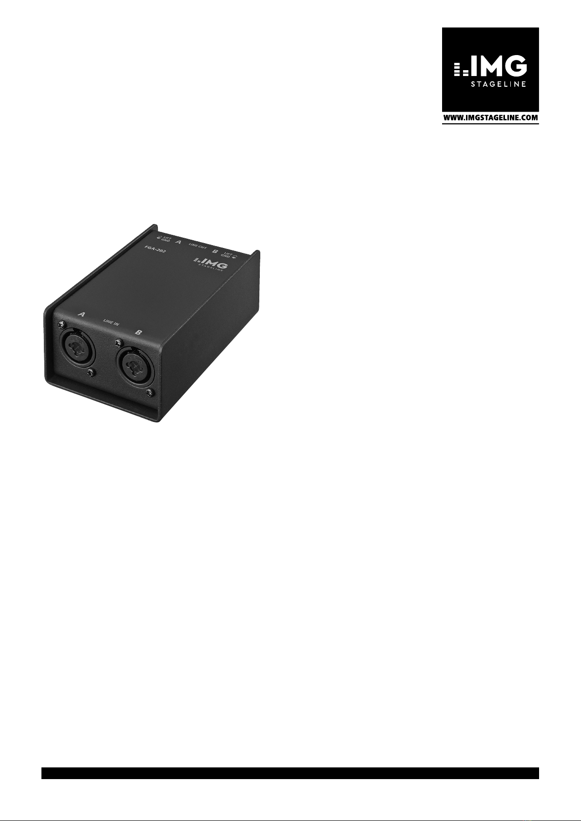
2-Kanal-Übertrager für Line-Signale
2-Channel Transformer for Line Signals
FGA-202
Bestellnummer • Order Number 0251660
BEDIENUNGSANLEITUNG
INSTRUCTION MANUAL
ISTRUZIONI PER L’USO
MODE D’EMPLOI
MANUAL DE INSTRUCCIONES
INSTRUKCJA OBSŁUGI

2
Français
Français Page
Italiano
Italiano Pagina
Español
Español Página
Nederlands
Nederlands Pagina
Polski
Polski Strona
DeutschEnglish
English
English Page
Deutsch
Deutsch Seite
2-Kanal-Übertrager für
Line-Signale
Diese Anleitung richtet sich an Benutzer mit
Grundkenntnissen in der Audiotechnik. Bitte
lesen Sie die Anleitung vor dem Betrieb gründ-
lich durch und heben Sie sie für ein späteres
Nachlesen auf.
1 Einsatzmöglichkeiten
Das Gerät FGA-202 hilft in Audioanlagen stö-
rendes Brummen, das durch Masseschleifen
verursacht wird, zu beseitigen. Masseschleifen
können entstehen, wenn zwei Geräte sowohl
über die Signalmasse als auch über den Schutz-
leiter der Stromversorgung oder eine leitende
Verbindung der Gehäuse im Rack Kontakt
haben. Eine Masseschleife entsteht z.B. auch,
wenn der Audioausgang eines über den Schutz-
kontakt seines Netzsteckers geerdeten PC an
eine Stereoanlage angeschlossen wird, die
bereits über den Antenneneingang des Radio-
empfängers geerdet ist. Durch spezielle Audio-
übertrager wird im FGA-202 eine galvanische
Trennung von Ein- und Ausgangssignal erreicht.
An das Gerät können Audioquellen mit
symmetrischen oder asymmetrischen Line-Sig-
nalen angeschlossen werden. Es eignet sich
damit auch zum Symmetrieren von Signal-
ausgängen, wodurch die Signalübertragung
unempfindlicher gegen Störungen wird. Ein
Groundlift-Schalter für jeden Kanal ermöglicht,
die Signalmasse des jeweiligen Ein- und Aus-
gangs zu trennen.
2-Channel Transformer
for Line Signals
These instructions are intended for users with
basic knowledge of audio technology. Please
read these instructions carefully prior to opera-
tion and keep them for later reference.
1 Applications
The device FGA-202 is used to eliminate inter-
fering hum noise caused by ground loops in
audio systems. Ground loops may occur when
two devices have contact both via the signal
ground and via the earthed conductor of the
power supply or a conductive connection of
the housings in the rack. A ground loop also
occurs, for example, when the audio output
of a PC earthed via the earthing contact of
its mains plug is connected to a stereo system
which is already earthed via the antenna input
of the radio receiver. Special audio transformers
provide a galvanic isolation of input signal and
output signal in the device FGA-202.
The device allows connection of audio
sources with balanced or unbalanced line sig-
nals. Thus, it is also suitable for balancing signal
outputs which makes the signal transmission
less susceptible to interference. A ground lift
switch for each channel allows to separate the
signal ground of the corresponding input and
output.
2 Wichtige Hinweise
Das Produkt entspricht allen relevanten Richt-
linien der EU und trägt deshalb das -Zeichen.
•
Verwenden Sie das Produkt nur im Innen-
bereich und schützen Sie es vor Tropf- und
Spritzwasser sowie vor hoher Luftfeuchtig-
keit. Der zulässige Einsatztemperaturbereich
beträgt 0– 40°C.
•
Säubern Sie das Produkt nur mit einem tro-
ckenen, weichen Tuch, niemals mit Wasser
oder Chemikalien.
•
Wird das Produkt falsch verwendet oder
nicht fachgerecht repariert, kann keine Haf-
tung für daraus resultierende Sach- oder
Personenschäden und keine Garantie für das
Produkt übernommen werden.
Soll das Produkt endgültig aus dem
Betrieb genommen werden, entsor-
gen Sie es gemäß den örtlichen Vor-
schriften.
2 Important Notes
The product corresponds to all relevant direc-
tives of the EU and is therefore marked with .
The product corresponds to the relevant UK
legislation and is therefore marked with UKCA.
•
The product is suitable for indoor use only.
Protect it against dripping water, splash
water and high air humidity. The admissible
ambient temperature range is 0–40°C.
•
For cleaning only use a dry, soft cloth; never
use water or chemicals.
•
No guarantee claims for the product and no
liability for any resulting personal damage
or material damage will be accepted if the
product is not correctly used or not expertly
repaired.
If the product is to be put out of
operation definitively, dispose of the
product in accordance with local reg-
ulations.
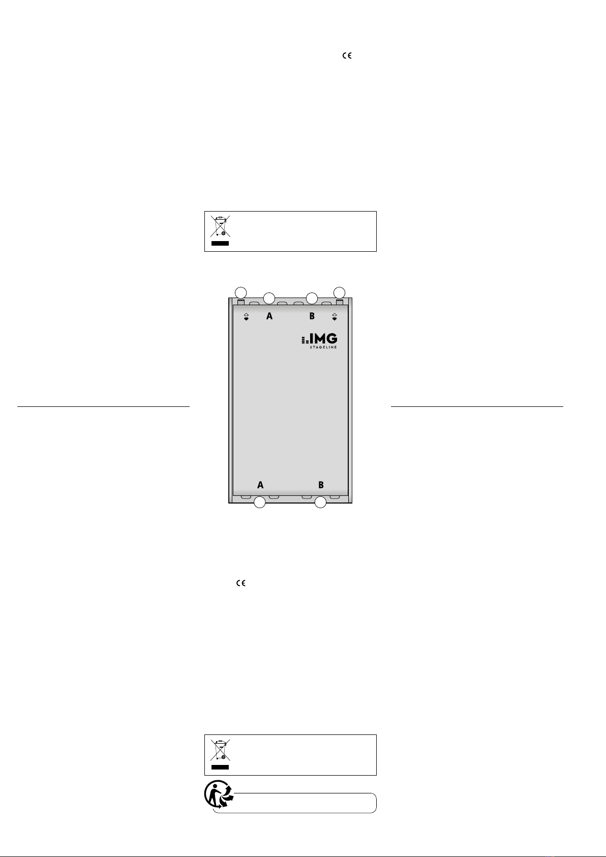
3 Anschlüsse herstellen
1) Zur Vermeidung von Schaltgeräuschen die
Signalwege der anzuschließenden Geräte
stummschalten.
2) Den Ausgang der Audioquelle an die Ein-
gangsbuchsen LINE IN (1) anschließen.
An die kombinierten XLR-/6,3-mm-Klin-
kenbuchsen können sowohl XLR-Stecker
als auch Klinkenstecker mit symmetrischen
oder asymmetrischen Signalen angeschlos-
sen werden. Das Ausgangssignal ist in jedem
Fall symmetrisch.
3) Die Ausgänge LINE OUT (2) mit den Eingän-
gen des nachfolgenden Audiogerätes (z.B.
Mischpult, Verstärker) verbinden.
4) Wenn nötig, den jeweiligen Groundlift-Schal-
ter (3) von der Position GND auf die Position
LIFT (Massen getrennt) umschalten.
4 Technische Daten
Frequenzbereich: . . . . . . . 20– 20000 Hz
Eingangsimpedanz:. . . . . . 600Ω bei 1 kHz
Ausgangsimpedanz: . . . . . 600Ω bei 1 kHz
Optimale Quellimpedanz: . 50 –600 Ω
Optimale Lastimpedanz: . . ≥ 5kΩ
Max. Eingangsspannung
bei 1% Klirrfaktor, 40 Hz: . 5V
Abmessungen: . . . . . . . . . 125 × 55 × 75mm
Gewicht:. . . . . . . . . . . . . . 650g
Änderungen vorbehalten.
3 Connections
1) To prevent switching noise, mute the signal
ways of the devices to be connected.
2) Connect the output of the audio source to
the input jacks LINE IN (1).
It is possible to connect both XLR plugs
and 6.3mm plugs with balanced or unbal-
anced signals to the combined XLR / 6.3mm
jacks. The output signal is balanced in any
case.
3) Connect the outputs LINE OUT (2) to the
inputs of the following audio device (e.g.
mixer, amplifier).
4) If required, switch the corresponding ground
lift switch (3) from position GND to position
LIFT (grounds separated).
4 Specifications
Frequency range: . . . . . . . 20– 20000 Hz
Input impedance: . . . . . . . 600Ω at 1 kHz
Output impedance:. . . . . . 600Ω at 1 kHz
Optimum
source impedance: . . . . . . 50– 600Ω
Optimum
load impedance: . . . . . . . . ≥ 5 kΩ
Max. input voltage
at 1% THD, 40 Hz: . . . . . . 5V
Dimensions: . . . . . . . . . . . 125 × 55 × 75mm
Weight: . . . . . . . . . . . . . . 650g
Subject to technical modification.
FGA-202
LINE IN
LINE OUT LIFT
GND
LIFT
GND
3 3
1 1
2 2
3
ItalianoFrançais
Italiano
Italiano Pagina
Français
Français Page
Transformateur 2 canaux
pour signaux Ligne
Cette notice s‘adresse aux utilisateurs avec des
connaissances techniques de base en audio.
Veuillez lire la présente notice avant le fonc-
tionnement et conservez-la pour pouvoir vous
y reporter ultérieurement.
1 Possibilités d’utilisation
L’appareil FGA-202 permet d’éliminer dans des
installations audio tout ronflement perturbateur
causé par des boucles de masse. Les boucles de
masse peuvent apparaître lorsque deux appa-
reils ont un contact non seulement via la masse
de signal mais aussi via le conducteur terre de
l’alimentation ou via une connexion conduc-
trice des boîtiers dans le rack. Une boucle de
masse apparaît par exemple également lorsque
la sortie audio d’un PC mis à la terre via le
contact terre de sa fiche secteur est reliée à
une installation stéréo, déjà mise à la terre par
l’entrée d’antenne du récepteur radio. Par des
transformateurs audio spéciaux, une sépara-
tion galvanique du signal d’entrée et de sortie
est obtenue dans le FGA-202.
L’appareil permet de connecter des sources
audio avec des signaux Lignes symétriques ou
asymétriques. Il est ainsi adapté pour symétriser
des sorties de signal, la transmission de signal
est alors moins sensible aux interférences. Un
interrupteur Groundlift pour chaque canal per-
met de séparer la masse de signal de l’entrée et
de la sortie respective.
Trasformatore a 2 canali
per segnali line
Queste istruzioni sono rivolte a utenti con cono-
scenze base nella tecnica audio. Vi preghiamo
di leggerle attentamente prima della messa in
funzione e di conservarle per un uso futuro.
1 Possibilità d’impiego
L’apparecchio FGA-202 è di aiuto negli impianti
audio per eliminare il fastidioso ronzio provo-
cato da anelli di terra. Tali anelli possono es-
sere generati quando due apparecchi sono in
contatto sia attraverso la masse dei segnali che
attraverso il conduttore di terra dell’alimen-
tazione oppure attraverso un collegamento
conduttivo fra i contenitori nel rack. Un anello
di terra si crea anche, per esempio, se l’uscita
audio di un PC, collegato con la terra attraverso
l’apposito contatto della sua spina di rete, viene
collegata con un impianto stereo già messa a
terra attraverso l’ingresso per antenna del ri-
cevitore radio. Nell FGA-202, dei trasformatori
audio speciali producono una separazione gal-
vanica fra i segnali d’ingresso e d’uscita.
All’apparecchio si possono collegare sor-
genti audio con segnali line simmetrici o asim-
metrici. Pertanto è adatto anche per la simme-
trizzazione di uscite di segnali, riducendo in
questo modo la sensibilità della trasmissione
nei confronti delle interferenze. Un interruttore
groundlift per ogni canale offre la possibilità di
separare la massa del segnale del suo ingresso
e della sua uscita.
2 Conseils importants
Le produit
répond à toutes les directives néces-
saires de l’Union européenne et porte donc le
symbole
.
•
Le produit n’est conçu que pour une utilisa-
tion en intérieur. Protégez-le des éclabous-
sures, de tout type de projections d’eau et
d’une humidité élevée de l’air. La tempéra-
ture ambiante admissible est 0–40°C.
•
Pour le nettoyer, utilisez uniquement un chif-
fon sec et doux, en aucun cas de produits
chimiques ou d’eau.
•
Nous déclinons toute responsabilité en cas de
dommages corporels ou matériels résultants
si le produit n’est pas correctement utilisé ou
réparé; en outre, la garantie deviendrait ca-
duque.
Lorsque le produit est définitivement
retiré du service, éliminez-le confor-
mément aux directives locales.
CARTONS ET EMBALLAGE
PAPIER À TRIER
2 Avvertenze importanti
Il prodotto è conforme a tutte le direttive rile-
vanti dell’UE e pertanto porta la sigla .
•
Il prodotto è adatto solo per uso interno. Pro-
teggerlo da gocce e spruzzi d’acqua e da un’e-
levata umidità dell’aria. L’intervallo di tempe-
ratura ambiente ammissibile è 0– 40°C.
•
Per la pulizia usare solo un panno morbido e
asciutto; non impiegare in nessun caso pro-
dotti chimici o acqua.
•
Non si accettano richieste di garanzia per il
prodotto e nessuna responsabilità per even-
tuali danni alle persone o alle cose che ne
derivano, se il prodotto non viene usato
correttamente o non viene riparato a regola
d’arte.
Se il prodotto deve essere messo defi-
nitivamente fuori uso, smaltire il pro-
dotto in conformità alle norme locali.
3 Branchements
1) Pour éviter tout bruit de commutation, cou-
pez le son des voies de signal des appareils
à relier.
2) Reliez la sortie de la source audio aux prises
d’entrée LINE IN (1).
On peut relier aux prises combinées XLR/
jack 6,35, aussi bien des fiches XLR mâles
que des fiches jack avec signaux symétriques
ou asymétriques. Le signal de sortie est dans
tous les cas symétrique.
3) Reliez les sorties LINE OUT (2) aux entrées de
l’appareil audio suivant (par exemple table
de mixage, amplificateur).
4) Si besoin, commutez l’interrupteur Ground-
lift (3) correspondant de la position GND sur
la position LIFT (masses séparées).
4 Caractéristiques techniques
Bande passante :. . . . . . . . . 20– 20000 Hz
Impédance d’entrée : . . . . . 600Ω sous 1 kHz
Impédance de sortie : . . . . . 600Ω sous 1 kHz
Impédance source optimale : 50 –600 Ω
Impédance de charge
optimale : . . . . . . . . . . . . . . ≥ 5 kΩ
Tension d’entrée max. à taux
de distorsion 1%, 40 Hz : . . 5 V
Dimensions :. . . . . . . . . . . . 125 × 55 × 75mm
Poids :. . . . . . . . . . . . . . . . . 650g
Tout droit de modification réservé.
3 Eseguire i collegamenti
1) Per escludere rumori di collegamento con-
viene mettere su muto le vie dei segnali degli
apparecchi da collegare.
2) Collegare l’uscita della sorgente audio con le
prese d’ingresso LINE IN (1).
Alle prese combi XLR/jack 6,3 mm si pos-
sono collegare sia connettori XLR che jack
con segnali simmetrici ed asimmetrici. In ogni
caso, il segnale d’uscita è simmetrico.
3) Collegare le uscite LINE OUT (2) con gli in-
gressi dell’apparecchio audio a valle (p.es.
mixer, amplificatore).
4) Se necessario, spostare il relativo interruttore
groundlift (3) dalla posizione GND in posi-
zione LIFT (masse separate).
4 Dati tecnici
Gamma di frequenze: . . . . 20 –20 000Hz
Impedenza d’ingresso: . . . 600Ω con 1 kHz
Impedenza d’uscita: . . . . . 600Ω con 1 kHz
Impedenza ottimale
della sorgente: . . . . . . . . . 50– 600Ω
Impedenza ottimale
del carico:. . . . . . . . . . . . . ≥ 5kΩ
Tensione max. d’ingresso
con fattore
di distorsione 1%, 40 Hz: . 5 V
Dimensioni:. . . . . . . . . . . . 125 × 55 × 75mm
Peso:. . . . . . . . . . . . . . . . . 650g
Con riserva di modifiche tecniche.
FGA-202
LINE IN
LINE OUT LIFT
GND
LIFT
GND
3 3
1 1
2 2

Deutsch
Deutsch Seite
English
English Page
Français
Français Page
Italiano
Italiano Pagina
Nederlands
Nederlands Pagina
EspañolPolski
Polski
Polski Strona
Español
Español Página
Transformador de 2canales
para señales de línea
Estas instrucciones van dirigidas a usuarios con
conocimientos básicos en audio. Lea atenta-
mente estas instrucciones antes de utilizar el
aparato y guárdelas para usos posteriores.
1 Aplicaciones
El aparato FGA-202 sirve para eliminar ruido
de zumbido que interfiere, causado por bucles
de masa en sistemas de audio. Se pueden pro-
ducir bucles de masa cuando dos aparatos en-
tran en contacto mediante la masa de señal y
mediante el conductor conectado a tierra de la
alimentación o una conexión conductora de las
carcasas en el rack. Un bucle de masa también
se produce, p.ej. cuando la salida de audio de
un PC conectado a tierra mediante el contacto
a tierra de su toma de red está conectada a un
sistema estéreo que ya está conectado a tierra
mediante la entrada de antena del receptor de
radio. Los transformadores de audio especiales
permiten un aislamiento galvánico de señal de
entrada y señal de salida en el FGA-202.
El aparato permite la conexión de fuentes
de audio con señales de línea simétricas o asi-
métricas. Por eso, también está indicado para
hacer simétricas las salidas de señal que hace la
transmisión de señal menos sensible a las inter-
ferencias. Un interruptor groundlift para cada
canal permite separar la masa de señal de la
entrada y la salida correspondiente.
2-kanałowy
transformator liniowy
Niniejsza instrukcja przeznaczona jest dla użyt-
kowników posiadających co najmniej pod-
stawową wiedzą z zakresu technologii audio.
Przed rozpoczęciem użytkowania proszę zapo-
znać się z instrukcją, a następnie zachować ją
do wglądu.
1 Zastosowanie
Transformator FGA-202 pomaga w eliminowa-
niu przydźwięku sieciowego spowodowanego
pętlą mas w systemach audio. Pętla masy po-
wstaje gdy dwa urządzenia są połączone ze
sobą elektrycznie w stojaku rack przez masę sy-
gnałową oraz przez przewód uziemiający kabla
zasilającego lub przez obudowę. Pętla masy
powstaje również np. gdy wyjście audio kom-
putera z uziemieniem przez styk uziemiający
wtyku sieciowego jest podłączone do systemu
stereo uziemionego przez wejście antenowe
odbiornika radiowego. Specjalne transforma-
tory audio zapewniają izolację galwaniczną sy-
gnału wejściowego i wyjściowego.
Model FGA-202 przeznaczony jest zarówno
do sygnałów liniowych symetrycznych, jak i nie-
symetrcznych, jest więc przystosowany do sy-
metryzowania wyjść sygnałowych, dzięki czemu
transmisja sygnału jest mniej podatna na zakłó-
cenia. Włącznik Groundlift dla każdego kanału
umożliwia przerwanie pętli masy danego wej-
ścia i wyjścia.
2 Notas importantes
El producto cumple con todas las directivas per-
tinentes de la UE y, por tanto, lleva la marca .
•
Utilice el producto sólo en interiores. Proté-
jalo de gotas/salpicaduras de agua, así como
de la alta humedad. El rango de temperatura
de uso admisible es de 0°C a 40 °C.
•
Limpie el producto siempre con un paño seco
y suave, nunca con agua o productos quími-
cos.
•
Si el producto se utiliza de forma incorrecta
o no se repara profesionalmente, no se acep-
tará ninguna responsabilidad por los daños
materiales o personales resultantes y no se
ofrecerá ninguna garantía por el producto.
Si el producto debe ser retirado defi-
nitivamente del servicio, elimínelo de
acuerdo con la normativa local.
2 Bezpieczeństwo użytkowania
Urządzenie spełnia wszystkie wymagania norm
UE i dlatego posiada oznaczenie symbolem .
•
Urządzenie przeznaczone jest wyłącznie do
użytku wewnątrz pomieszczeń. Należy chro-
nić je przez wodą, dużą wilgotnością oraz
wysoką temperaturą. Dopuszczalny zakres
temperatur wynosi 0– 40°C.
•
Do czyszczenia urządzenia należy używać su-
chej, miękkiej tkaniny. Nie wolno stosować
wody ani chemicznych środków czyszczących.
•
Producent ani dostawca nie ponoszą odpo-
wiedzialności za wynikłe szkody (uszkodze-
nie sprzętu lub obrażenia użytkownika), jeśli
urządzenie używano niezgodnie z przezna-
czeniem, nieprawidłowo podłączono, ob-
sługiwano bądź poddano nieautoryzowanej
naprawie.
Po całkowitym zakończeniu eksplo-
atacji urządzenia, należy oddać je do
punktu recyklingu, aby nie zaśmiecać
środowiska.
3 Conexiones
1) Para prevenir ruido de conmutación, silencie
las vías de señal de los aparatos que deban
ser conectados.
2) Conecte la salida de la fuente de audio a los
jacks de entrada LINE IN (1).
Es posible conectar tomas XLR y tomas
6,3mm con señales simétricas o asimétricas
a los jacks XLR/6,3mm combinados. La señal
de salida es simétrica en cualquier caso.
3) Conecte las salidas LINE OUT (2) a las en-
tradas del aparato de audio siguiente (p.ej.
mezclador, amplificador).
4) Si es necesario, conmute el interruptor
groundlift correspondiente (3) de la posición
GND a la posición LIFT (masas separadas).
4 Características técnicas
Banda pasante:. . . . . . . . . 20–20000Hz
Impedancia de entrada: . . 600Ω a 1 kHz
Impedancia de salida: . . . . 600Ω a 1 kHz
Impedancia óptima
de la fuente: . . . . . . . . . . . 50 –600 Ω
Impedancia óptima
de la carga:. . . . . . . . . . . . ≥ 5 kΩ
Voltaje de entrada máx.
a tasa de
distorsión 1%, 40 Hz: . . . . 5V
Dimensiones, peso:. . . . . . 125 × 55 × 75mm,
650g
Sujeto a modificaciones técnicas.
3 Połączenia
1) Przed rozpoczęciem podłączania należy wy-
ciszyć tory sygnałowe podłączanych urzą-
dzeń aby uniknąć powstania trzasków pod-
czas włączania.
2) Do gniazd LINE IN (1) należy podłączyć wyj-
ście źródła sygnału.
Do gniazd XLR/ 6,3mm można podłą-
czać zarówno wtyki XLR, jak i wtyki 6,3mm,
symetryczne lub niesymetryczne. Sygnał wyj-
ściowy jest symetryczny.
3) Należy połączyć wyjścia LINE OUT (2) z wej-
ściami kolejnego urządzenia audio (np. mik-
sera, wzmacniacza).
4) W razie potrzeby można włączyć funkcję
Groundlift zmieniając pozycję włącznika (3)
z GND na LIFT (przerwanie pętli masy).
4 Dane techniczne
Pasmo przenoszenia:. . . . . 20– 20000 Hz
Impedancja wejściowa: . . 600 Ω/1kHz
Impedancja wyjściowa: . . . 600Ω /1kHz
Optymalna impedancja
źródła: . . . . . . . . . . . . . . . 50– 600Ω
Optymalna impedancja
obciążenia: . . . . . . . . . . . . ≥ 5kΩ
Maks. napięcie wejściowe
przy 1% THD, 40 Hz: . . . . 5 V
Wymiary, waga: . . . . . . . . 125 × 55 × 75mm,
650g
Z zastrzeżeniem możliwości zmiany.
© MONACOR INTERNATIONAL
All rights reserved
A-1803.99.04.10.2023
MONACOR INTERNATIONAL GmbH & Co. KG
Zum Falsch 36, 28307 Bremen
Germany
FGA-202
LINE IN
LINE OUT LIFT
GND
LIFT
GND
3 3
1 1
2 2
This manual suits for next models
1
Other IMG STAGE LINE Transformer manuals


Popular Transformer manuals by other brands


Pulsar
Pulsar AWT845 Assembly instructions

Pulsar
Pulsar AWT268 quick start guide

Monacor
Monacor FGA-30M quick start guide

Pro-Ject Audio Systems
Pro-Ject Audio Systems MC Step Up Box S3 Instructions for use

Aetechron
Aetechron 8300 Series Operator's manual

Alarm SAF
Alarm SAF CPS100 installation instructions


