HQ Power PROMIX66N User manual

P
6
-
P
R
T
A
M
P
R
P
R
U
S
G
E
M
O
M
A
B
E
I
N
P
RO
M
-
CHAN
N
R
OFESSI
A
BLE D
E
ESA DE
R
OFES
S
R
OFESJ
S
ER MAN
E
BRUIKE
R
O
DE D’E
M
A
NUAL D
E
DIENUN
N
STRUKC
J
M
IX6
6
N
EL/8-C
ONEEL
6
E
MIXA
G
MEZCL
A
S
IONEL
L
ONALN
Y
UA
L
R
SHAND
L
M
PLOI
EL USUA
R
GSANLEI
T
J
A OBSŁ
U
6
N/P
R
HANNE
L
6
-KANAA
L
G
E
À
6/
A
S PRO
L
ES 6-K
A
Y
MIKS
E
L
EIDING
R
IO
T
UNG
U
GI
R
OM
I
L
PROF
E
L
S / 8-K
A
8 CANA
FESIO
N
A
NAL-
/
E
R 6-CI
2
8
1
4
19
25
31
I
X88
N
E
SSION
A
NAALS
M
UX
N
AL DE
6
/
8-KA
N
O/8-MI
4
N
AL MIX
M
ENGPA
6
/8 CA
N
N
AL-MI
S
O KAN
A
ER
NEE
L
N
ALES
S
CHPUL
T
A
ŁOWY
T

V.
1
.
T
o
I
m
Th
If
t
2
.
Re
•
•
•
•
•
•
3
.
M
O
1.
Ea
s
w
(g
r
2.
Th
dr
u
su
c
lin
e
an
N
o
si
m
01 – 30/10/2
.
Intr
o
o
all reside
n
m
portant e
n
This
har
m
shou
distri
If in
ank you for
t
he device
w
.
Safe
t
Be v
e
Ind
o
put
o
Alwa
are
p
fer to the V
e
Damage c
a
dealer will
A qualified
Do not sw
i
device ag
a
Do not ex
p
device.
Note that
d
Keep the
d
.
Des
c
O
NO Inp
u
MIC Input
ch mono in
p
w
itchable +4
8
r
ound), pin
2
LINE IN
e LINE inpu
t
u
m machine
c
h as those
e
input, the
n
d the sleev
e
o
te: Either t
h
m
ultaneousl
y
012
o
duction
n
ts of the
E
n
vironmen
t
symbol on t
h
m
the enviro
n
ld be taken
t
butor or to
a
doubt, co
n
choosing H
Q
w
as damage
d
t
y Instr
u
e
ry careful
d
o
or use onl
y
o
bjects filled
ys disconne
c
p
erformed.
H
e
lleman®
S
a
used by di
s
not accept
r
technician
s
i
tch the devi
a
inst damag
e
p
ose the de
v
d
amage cau
d
evice away
c
ription
u
t Chann
p
ut channel
o
8
V phanto
m
2
(positive (
t
is designe
d
s or sample
r
from an un
b
n
a 1/4" TR
S
e
(ground).
h
e MIC or t
h
y
to the sa
m
E
uropean U
n
t
al informa
t
h
e device o
r
n
ment. Do n
t
o a speciali
a
local recy
c
n
tact your l
Q
Power™! P
l
d
in transit,
u
ctions
d
uring the i
n
y
. Keep this
with liquid
s
c
t mains po
w
H
andle the p
S
ervice an
d
s
regard of c
e
r
esponsibilit
y
s
hould insta
ce on imme
e
by leaving
v
ice to liquid
sed by user
from childr
e
el (fig. 1
o
ffers a bal
a
m
power sup
+)) and pin
d
to accept
b
r
s. There is
b
alanced mi
c
S
(stereo) p
h
h
e LINE inpu
m
e channel.
PROMI
X
USE
n
ion
t
ion about
t
r
the packag
ot dispose
o
zed compan
c
ling service
.
ocal waste
l
ease read t
h
don't install
n
stallation: t
o
device awa
y
s
on top of o
w
er when d
e
ower cord b
d
Q
uality
W
e
rtain guidel
y
for any en
ll and servi
c
diately afte
r
it switched
s and make
modificatio
n
e
n and unau
t
)
a
nced micro
p
ply for cond
e
3 (negative
b
alanced or
u
enough gai
n
c
rophone or
h
one plug s
h
t of a given
X
66N/PRO
2
R MA
N
t
his produ
c
e indicates
t
o
f the unit (
o
y for recycli
.
Respect th
e
disposal a
h
e manual t
h
or use it an
o
uching live
y
from rain,
r close to th
e
vice not in
u
y the plug
o
W
arranty on
ines in this
m
suing defec
t
c
e this devic
e
r
it has been
off until it h
a
sure not to
n
s to the de
v
t
horised us
e
p
hone input
e
nser micro
p
(-)).
u
nbalanced
n
available o
guitar outp
u
h
ould be wir
e
channel ca
n
MIX88N
N
UAL
c
t
t
hat disposa
o
r batteries)
ng. This de
v
e
local envi
r
uthorities.
h
oroughly b
e
d contact y
o
wires can c
a
moisture, s
e device.
u
se or when
o
nly.
the last pa
g
m
anual is n
o
t
s or proble
m
e
.
exposed to
a
s reached
r
place any o
b
v
ice is not c
o
e
rs.
via the XLR
p
hones. Th
e
line level si
g
n the line in
u
t. If a bala
n
e
d for the ti
p
n
be connec
t
l of the devi
as unsorte
d
v
ice should
b
r
onmental r
u
e
fore bringi
n
o
ur dealer.
a
use life-th
r
plashing an
d
servicing o
r
g
es of this
m
o
t covered b
m
s.
changes in
r
oom tempe
b
ject contai
n
o
vered by t
h
connector
a
e
XLR jack is
g
nals such a
s
put to acce
p
n
ced signal i
p
(positive (
t
ed at one ti
m
ce after its l
d
municipal
w
b
e returned
t
u
les.
n
g this devi
c
r
eatening el
e
d
dripping li
q
r
maintenan
m
anual.
y the warra
n
temperatur
e
rature.
n
ing liquid o
h
e warranty.
a
nd also fea
t
configured
f
s
those fro
m
p
t even low
e
s to be con
n
+)), the rin
g
m
e. Never c
©Vellema
n
ifecycle cou
l
w
aste; it
t
o your
c
e into servi
c
e
ctroshocks.
q
uids. Neve
r
ce activities
n
ty and the
e
. Protect th
n top of the
t
ures a
f
or pin 1
m
keyboards
,
e
r level sign
a
n
ected to th
e
g
(negative
(
onnect both
n
nv
l
d
c
e.
r
e
,
a
ls
e
(
-))

PROMIX66N/PROMIX88N
V. 01 – 30/10/2012 3 ©Velleman nv
3. TRIM Control
The TRIM control adjusts the input sensitivity (channel gain) of the MIC and LINE inputs
on the mono input channels. This control can be adjusted to accommodate input signals
from a wide variety of sources, from the high outputs from keyboards or drum machines
to the small signal outputs of microphones. This wide range eliminates the need for MIC /
LINE switching. The best S/N balance and dynamic range will be achieved if you adjust
the TRIM control on each channel separately so that the PEAK LED (7) for that channel
lights occasionally.
Note: This control should always be turned fully anticlockwise whenever you connect or
disconnect a signal source to one of the inputs.
4. EQUALIZER Controls
All mono input channels are fitted with three-band EQ. The upper (HIGH) and lower
(LOW) shelving controls have their frequencies fixed at 12 kHz and 80 Hz respectively.
The midrange control has a peaking response, with Q fixed at 2 octaves and the
frequency at 2.5 kHz. All three bands have up to 15 dB of cut and boost with a centre
detent for “off”.
5. AUX / EFF SEND Control
The AUX / EFF controls are mono and post-EQ and post-fader. The signal level sent to
the AUX / EFF bus will be affected by the channel fader setting. The AUX configuration is
ideal for almost all monitoring purpose e.g. for a separate stage monitor mix in live
performances or a studio room monitor in recording applications, such as for a
headphone cue system. The EFF controls the adjustment of level sent by each channel to
the internal DSP (Digital Sound Processor).
6. PAN Control
The channel PAN positions the output of the channel in the stereo field of the Master Mix.
Its constant-power design ensures there are no level discrepancies whether a signal is
hard-panned, centre-stage or somewhere in-between.
7. PEAK Indicator
The PEAK LED illuminates when a channel is going into overload. It detects the peak level
after the EQ and will light at 3 dB before clipping to warn that the signal is approaching
overload. You do not want the PEAK LED to light except very intermittently during a take
or a mix. If it does light persistently, reduce input gain with the TRIM control (3).
8. CHANNEL GAIN Control
The channel GAIN controls determine the output signal level to the master mix bus.
There is no PFL function on the mixer. In order to audition any single channel for proper
gain, you can turn off the gain control of all the other channels (fully anticlockwise) and
set both the auditioned channel and MASTER MIX control (29) to unity gain (0 dB). The
LED OUTPUT meter (21) should read around 0 dB.
STEREO Input Channel (fig. 2)
4. EQUALIZER Controls
The stereo channel EQs operate in the same manner as those in the mono channels. The
left and right signals will be affected equally. A stereo equalizer is generally preferable to
using two mono equalizers when equalizing a stereo signal as it avoids possible
discrepancies between the left and right settings.
5.AUX / EFF SEND Control
These are the same as for the mono channels. Note that a mono sum is taken from the
stereo input.
8. CHANNEL GAIN CONTROL
The channel GAIN controls determine the output signal level to the MASTER MIX bus.
There is no PFL function on the mixer. In order to audition any single channel for proper
gain you can turn off the gain control of all the other channels (fully anticlockwise) and
set both the auditioned channel and MASTER MIX control (29) to unity gain (0 dB). The
LED OUTPUT meter (21) should read around 0 dB.

PROMIX66N/PROMIX88N
V. 01 – 30/10/2012 4 ©Velleman nv
9. LINE IN
Each stereo channel has two balanced line level inputs on 1/4" TRS jacks for left and right channels (tip =
positive (+), ring = negative (-), sleeve = ground). If only the connector marked “L” (left) is used, the channel
operates in mono. The stereo channels are designed to handle typical line level signals. The input signals to
these jacks can be either balanced or unbalanced.
10. BAL Control
For a mono input to the L (MONO) input the function of the control is the same as the PAN controls (6) of the
mono channels. However, when a channel is run in stereo, this control functions as a BALANCE control,
determining the relative balance of the left and right channel signals being sent to the left and right MASTER
MIX buses. For example, with the BALANCE control turned fully clockwise, only the right portion of the
channel’s stereo signal will be routed to the MASTER MIX.
MASTER Section (fig. 3 & 4)
11. STEREO AUX RETURNS (LEFT / MONO, RIGHT)
The AUX RETURN jacks are the mono or stereo returns for AUX SEND. If you connect a signal to the LEFT /
MONO RETURN jack only, the AUX RETURN will operate in mono and the signal will be routed to the AUX
RETURN control (19) and then mixed into the left and right MASTER MIX stereo outputs (13). The separate left
and right return jacks are provided for use with stereo signals such as those from the output of a stereo effects
processor. The left and right return signals will be routed to the AUX RETURN level control (19) and mixed into
the left and right STEREO OUT (13) while maintaining stereo separation.
12. AUX SEND
The AUX SEND is the output for the signal sent from the channel AUX / EFF controls (5) and by the AUX SEND
controls (18) control. They are 1/4" unbalanced phone jacks (tip = positive (+), sleeve = ground). AUX SEND is
a post-fader. These signals can be sent to the input of an effects processor, multi-track recorder, or used for
any other line-level auxiliary purpose.
13. STEREO Outputs
Use these jacks to connect to an external power amplifier if extra output power for a larger PA system is
required. The stereo outputs are left (L) and right (R) unbalanced 1/4" phone jacks, wired as tip = positive (+),
sleeve = ground.
14. TAPE Inputs
These jacks will accept the signal from an external device with a stereo output such as a cassette recorder.
15. REC Outputs
The REC outputs also provide an output of the MASTER MIX. These outputs are RCA jacks and designed
primarily for inputs to tape recorders etc.
16. L-R Control Room Outputs
The L-R control room outputs can be connected to an amp to power stereo control room (or other) monitor
speakers and are 1/4" unbalanced phone jacks, wired as tip = positive (+), sleeve = ground.

PROMIX66N/PROMIX88N
V. 01 – 30/10/2012 5 ©Velleman nv
17. PHONES Output
The PHONES output will feed headphones and is a 1/4" TRS jack, wired as tip = left signal, ring = right signal,
sleeve = ground.
18. AUX SEND
This is a master control that adjusts the output signal level at the AUX SEND (12) jack.
19. AUX RETURN Control
The left and right return signals will be routed to the AUX RETURN level control and mixed into the left and right
stereo OUT (13) while maintaining stereo separation.
20. PHONES/CONTROL ROOM CONTROL
The mixer allows you to monitor the MASTER
MIX. The signal level is adjusted with the
PHONES / CONTROL ROOM control and routed to
both the CONTROL ROOM (16) and
HEADPHONES (17) outputs.
21. LED OUTPUT Meter
The 10-stage LED OUTPUT meter displays the
MASTER MIX output level.
22. PHANTOM POWER ON/OFF Switch
When using condenser microphones, +48 VDC
can be switched globally on or off to the XLR
MIC inputs for all mono channels. When this
switch is in the “ON” position, the PHANTOM
POWER ON LED (25) will light and +48 VDC will
be provided between pins 2 and 3 on all the
mono MIC input XLR connectors. If you do not
need phantom power, be sure to turn this switch
to the “OFF” position.
Note: It is safe to connect balanced dynamic
microphones or line-level devices even if this
switch is on, but connecting unbalanced devices
or devices whose transformers are centre-
grounded will cause hum or malfunctions.
Shorting the +48 VDC can also damage your
mixer. Also, mute the monitor or PA speakers
first when turning the phantom power on or off.
23. TAPE / REC TO CONTROL ROOM Switch
Use the TAPE / REC TO CONTOL ROOM switch to route signals from the TAPE input (14) to the PHONES /
CONTROL ROOM control (20).
24 TAPE / REC TO MASTER Switch
Use the TAPE / ECHO TO MASTER switch to route signals from the TAPE input (14) to the MASTER MIX GAIN
control (29).
25. PHANTOM POWER LED
The red +48V LED lights up when the phantom power is turned on.
26. POWER ON LED
The red LED indicates that the console is powered on.
DIGITAL EFFECTS Section
27. EFFECTS Display
Press either ECHO effect buttons to scroll in either direction through the 16 presets. The numeric effects display
will indicate which of the 16 effect presets has been selected.
28. ECHO EFFECT SELECT Buttons
The built-in DSP (Digital Sound Processor) offers 16 different preset level and echo intervals selectable by the
echo effect UP / DOWN buttons. The DSP processes the signal on the EFFECTS bus, which is the sum of the
mono and stereo channel inputs controlled by the EFF control (5).

PROMIX66N/PROMIX88N
V. 01 – 30/10/2012 6 ©Velleman nv
29. MASTER MIX GAIN Control
The output level routed to the stereo outputs and REC outputs is determined ultimately by the setting of the
MASTER MIX GAIN control.
30. EFFECT SEND
The EFFECT SEND control adjusts the level of the signal on the EFFECTS bus fed to the DSP.
31. EFFECT (ECHO) RETURN
The EFFECT (ECHO) RETURN control adjusts the number of repeats of the echo effect selected with the UP /
DOWN buttons (28).
32. EFFECT GAIN
The EFFECTS GAIN fader controls the signal level sent to the MASTER MIX buses.
Rear Panel (fig. 5)
33. AC POWER IN Socket
Connect the enclosed power supply to the 3-pin mains connector on the rear of the console. Use the included
adapter to connect the console to the mains.
34. MAIN POWER Switch
This switches the mixer ON or OFF.
Note: Be sure to switch on the power to your mixer before switching on the amplification system.
4. Connections
Unbalanced equipment may be connected to balanced inputs/outputs. Either use mono 1/4" jacks or connect
the ring and sleeve of TRS jacks. Never use unbalanced XLR connectors on the MIC input connectors when
using the phantom power supply.
Microphone input Group & mix outputs
Socket (female) Plug (male)
Headphones
1. Tip = left signal
2. Ring = right signal
3. Sleeve = ground
4. Tip
5. Ring
6. Sleeve
7. Strain relief clamp

PROMIX66N/PROMIX88N
V. 01 – 30/10/2012 7 ©Velleman nv
Unbalanced use of mono 1/4" plugs
1. Tip = signal
2. Sleeve = ground
3. Tip
4. Sleeve
5. Strain relief clamp
Balanced use of stereo 1/4" plugs
1. Tip = hot (+)
2. Ring = cold (-)
3. Sleeve = ground
4. Tip
5. Ring
6. Sleeve
7. Strain relief clamp
5. Technical Specifications
Input
Input Connector Input Impedance Nominal Level Max. Level
MONO CH MIC XLR > 1.3 kohm +2 dBm +14 dBm
MONO CH LINE ¼" TRS > 10 kohm +4 dBm +22 dBm
STEREO CH LINE ¼" TRS > 10 kohm +4 dBm +22 dBm
TAPE IN RCA PIN JACKS > 10 kohm +2 dBm +22 dBm
AUX RETURNS ¼" TRS > 10 kohm +4 dBm +22 dBm
Output
Output Connector Input Impedance Nominal Level Max. Level
STEREO OUT L/R ¼" TRS 120 ohm +4 ~ 6 dBm +22 dBm
AUX SEND ¼" TRS 120 ohm +4 ~ 6 dBm +20 dBm
CTRL R OUT ¼" TRS 120 ohm +4 ~ 6 dBm +22 dBm
REC OUT RCA PIN JACKS 1 kohm +4 ~ 6 dBm +22 dBm
PHONES ¼" TRS 100 ohm – 40 mW * 2
Frequency Response 20 Hz to 20 kHz
THD 0.02 %, 20 Hz ~ 20 kHz @ 1 kHz, 0 dBm
Input Channel Equalization
High 12 kHz, +/- 15 dB, Q fixed at 2 octaves
Mid 2.5 kHz, +/- 15 dB, Q fixed at 1 octave
Low 80 Hz, +/- 15 dB, Q fixed at 2 octaves
Gain Control Range
Input Channel Trim Control stop to stop, MIC +10 dB ~ +60 dB; LINE +10 dB ~ +40 dB
Channel/Master/Effect Faders -∞to +15 dB
Aux Send/Aux Master Send OFF to +15 dB
Aux Return OFF to +20 dB
Channel and Master Effects Send OFF to +15 dB

V.
Cr
o
H
u
V
U
Ph
Po
C
o
Di
m
W
e
U
s
of
F
o
w
w
T
h
©
T
h
N
o
wi
t
1
.
A
a
B
e
H
e
D
a
be
2
.
Ra
01 – 30/10/2
o
sstalk @ 1
u
m and Nois
e
Equivale
n
Residual
U
Meters
antom Pow
e
wer Supply
o
nsumption
m
ensions
PROMIX
6
PROMIX
8
e
ight
PROMIX
6
PROMIX
8
s
e this devi
damage o
r
o
r more inf
o
w
w.hqpow
e
h
e informa
t
COPYRIG
H
h
e copyrigh
o
part of this
t
hout the pr
i
.
Inlei
a
n alle ing
e
e
langrijke
m
Dit s
y
weg
g
batt
e
tere
c
bren
g
e
bt u vrage
a
nk u voor u
w
schadigd tij
d
.
Veili
g
Wee
s
elek
t
Geb
r
vloei
Trek
niet
g
adpleeg de
V
012
kHz
e
n
t Input Noi
s
Output Nois
e
r
6
6N
8
8N
6
6N
8
8N
ce with ori
r
injury res
o
concerni
n
e
r.eu.
t
ion in this
H
T NOTICE
t to this m
a
manual ma
i
or written c
din
g
e
zetenen v
a
m
ilieu-info
r
y
mbool op
h
g
eworpen, d
e
rijen) niet
b
c
htkomen v
o
g
en. Respe
c
n, contact
e
w
aankoop!
d
ens het tra
g
heidsi
n
s
voorzichti
g
t
roshocks te
r
uik het toes
stoffen. Pla
a
de stekker
u
g
ebruikt.
V
elleman
®
s
e
e
ginal acce
s
ulting fro
m
n
g this pro
d
manual is
s
a
nual is o
w
y be copied
,
onsent of t
h
GEB
R
a
n de Euro
p
r
matie bet
r
h
et toestel o
f
it toestel sc
h
b
ij het gewo
n
o
or recyclag
e
c
teer de pla
a
e
er dan de
Lees deze
h
nsport, inst
a
n
structie
g
bij de inst
a
vermijden.
tel enkel b
i
a
ts geen obj
e
u
it het stop
c
®
service- e
PROMI
X
-78 dB
~
20 Hz –
2
sensitivi
t
-129 dB
m
< 90 dB
m
10-seg
m
+48 VD
C
120 VAC
25 W
253 x 2
3
253 x 2
9
1.72 kg
2 kg
s
sories onl
y
m
(incorrec
t
d
uct and th
s
ubject to
c
w
ned by Ve
l
,
reproduce
d
h
e copyright
R
UIKE
R
p
ese Unie
r
effende di
t
f
de verpak
k
h
ade kan to
e
n
e huishoud
e
. U moet di
a
tselijke mili
e
plaatselijk
e
h
andleiding
g
a
lleer het da
s
a
llatie: raak
i
nnenshuis
e
cten gevul
d
c
ontact (tre
k
n kwaliteit
X
66N/PRO
8
~
-68 dB
2
0 kHz, Rs
=
t
y at -60 dB
m
m
m
ent LED x 2
C
/ 60 Hz or
2
3
6 x 55 mm
9
0 x 55 mm
y
. Vellema
n
t
) use of t
h
e latest ve
r
c
hange wit
l
leman nv.
d
, translated
holder.
R
SHA
N
t
product
k
ing geeft a
a
e
brengen a
a
elijke afval;
t toestel na
a
e
uwetgevin
g
e
autoritei
t
g
rondig voo
r
n niet en ra
a
geen kabels
. Bescherm
t
d
met vloeis
t
k
niet aan d
e
sgarantie
a
MIX88N
=
150 ohm,
2
30 VAC / 5
n
nv canno
t
is device.
r
sion of thi
hout prior
All world
w
or reduced
N
DLEI
D
a
n dat, als h
n het milie
u
het moet bi
a
r uw verdel
g
.
t
en betreff
e
r
u het toest
e
a
dpleeg uw
aan die on
d
t
egen regen
t
of op of na
a
e
kabel!) vo
o
a
chteraan d
e
input TRIM
0 Hz select
a
t
be held r
e
s manual,
p
notice.
w
ide rights
r
to any elec
t
D
ING
et na zijn le
v
u
. Gooi dit t
o
j een gespe
c
er of naar e
e
e
nd de ver
w
e
l in gebrui
k
dealer.
d
er stroom
s
, vochtighei
d
a
st het toes
t
o
rdat u het
t
e
ze handleid
@ 0 dB,
a
ble
e
sponsible
i
p
lease visi
t
r
eserved.
t
ronic mediu
v
enscyclus
w
o
estel (en e
v
c
ialiseerd b
e
e
n lokaal re
c
w
ijdering.
k
neemt. W
e
s
taan om do
d
d
en opspat
t
t
el.
t
oestel reini
g
ing.
©Vellema
n
i
n the eve
n
t
our webs
i
m or other
w
w
ordt
v
entuele
e
drijf
c
yclagepunt
rd het toest
d
elijke
t
ende
g
t en als u h
n
nv
n
t
i
te
w
ise
el
et

PROMIX66N/PROMIX88N
V. 01 – 30/10/2012 9 ©Velleman nv
•De garantie geldt niet voor schade door het negeren van bepaalde richtlijnen in deze handleiding en uw
dealer zal de verantwoordelijkheid afwijzen voor defecten of problemen die hier rechtstreeks verband mee
houden.
•Laat dit toestel installeren en onderhouden door een geschoolde technicus.
•Om beschadiging te vermijden, zet u het toestel best niet aan onmiddellijk nadat het werd blootgesteld aan
temperatuurschommelingen. Wacht tot het toestel op kamertemperatuur gekomen is.
•Houd het toestel uit de buurt van vloeistoffen en plaats geen drank op het mengpaneel.
•Schade door wijzigingen die de gebruiker heeft aangebracht aan het toestel vallen niet onder de garantie.
•Houd dit toestel uit de buurt van kinderen en onbevoegden.
3. Omschrijving
MONO ingangskanaal (zie fig. 1)
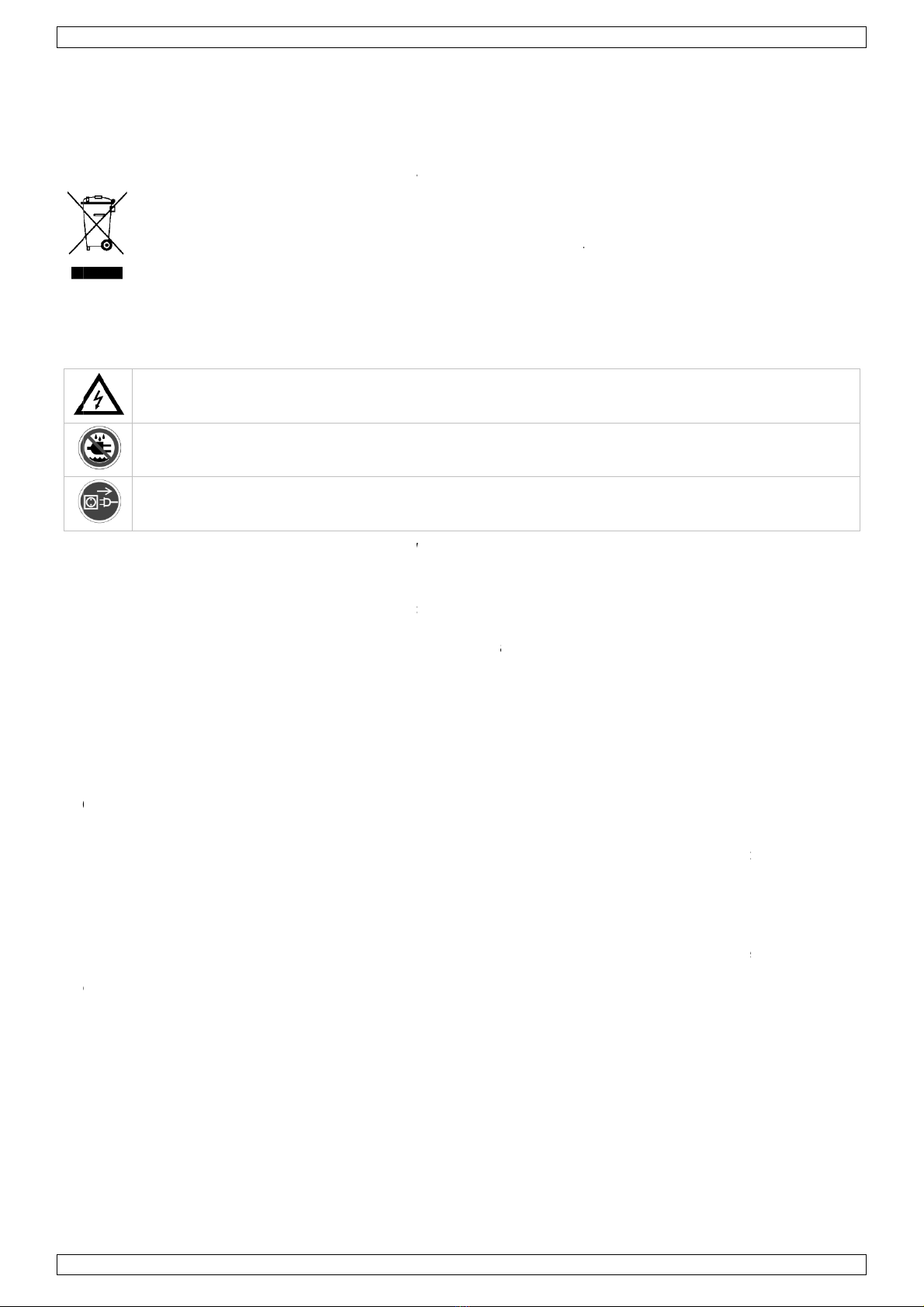
1. MIC-ingang
Elk mono ingangskanaal bestaat uit een gebalanceerde microfooningang via de XLR-aansluiting en beschikt
over een schakelende fantoomvoeding (+48 V) voor condensatormicrofoons. De XLR jack-aansluiting is
geconfigureerd voor pin 1 (aarding), pin 2 (positief (+)) en pin 3 (negatief (-)).
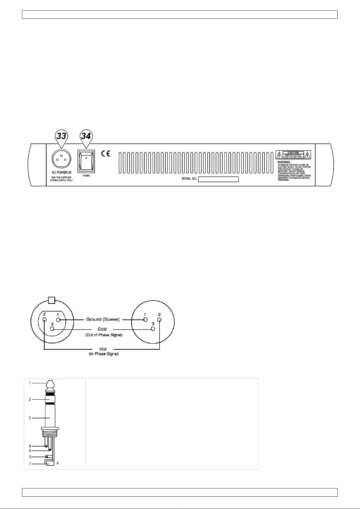
2. LINE IN
De LINE-ingang is ontworpen om gebalanceerde en niet-gebalanceerde line-signalen te ontvangen zoals die van
een keyboard, drumcomputer of sampler. Er is voldoende versterking aanwezig op de line-ingang om zelfs
zwakkere signalen zoals die van een ongebalanceerde microfoon of een gitaarsignaal te ontvangen. Wenst u
een gebalanceerd signaal aan de line-ingang te sluiten, bedraad een 1/4" TRS (stereo) plug als volgt: tip
(positief (+)), de ring (negatief (-)) en de huls (aarding).
OPMERKING: U kunt of de MIC-ingang of de LINE-ingang aansluiten. Sluit nooit beide tegelijkertijd op
eenzelfde kanaal.
3. TRIM-regeling
Met de TRIM-regeling regelt u de ingangsgevoeligheid (kanaalversterking) van de MIC-ingang en de LINE-
ingang van de mono ingangskanalen. Regel deze knop zodat u het ingangssignaal van verscheidene bronnen
kunt ontvangen, van de sterke uitgangssignalen ven een keyboard of drumcomputer tot de zwakke signalen
van een microfoon. Het grote bereik maakt MIC / LINE-schakeling overbodig. De beste S/R-verhouding en
dynamisch bereik verkrijgt u wanneer u de TRIM-regeling op elk kanaal afzonderlijk regelt zodanig dat de PEAK
LED (7) maar af en toe oplicht.
OPMERKING: Draai deze regelknop volledig naar links voordat u een signaal aansluit of ontkoppelt.
4. EQUALIZER
Alle mono ingangskanalen beschikken over een driebands equalizer. De bovenste (HIGH) en onderste (LOW)
potmeters hebben een frequentie van 12 kHz respectievelijk 80 Hz. De regelknop voor de middentonen heeft
een piekrespons met een Q van 2 octaven en een frequentie van 2.5 kHz. Alle drie banden hebben tot 15 dB
versterking of verzwakking met een centernok voor “off”.
5. AUX / EFF SEND
De AUX / EFF-regelknoppen zijn mono, post-EQ en post-fader. Het signaalniveau dat naar de AUX / EFF-bus
wordt gezonden, zal beïnvloed worden door de instelling van de fader. De AUX-configuratie is ideaal voor bijna
elke monitoring, bvb. een afzonderlijke geluidsregeling van de podiummonitor tijdens een live-optreden of een
geluidsregeling in een studio tijdens een opname zoals voor een hoofdtelefoon. De EFF regelt het niveau dat
elke kanaal naar de interne DSP (Digital Sound Processor) zendt.
6. PAN-regeling
De PAN-regeling plaatst de uitgang van een kanaal in het stereobeeld van de mix. Het toestel zorgt ervoor dat
er zich geen discrepanties in het niveau voorkomen, of een signaal nu langs een kant, centraal of ergens
tussenin staat.
7. PEAK-aanduiding
De PEAK-aanduiding licht op wanneer een kanaal overstuurt. Het toestel neemt een piek waar na de EQ, licht
op 3 dB voor de vervorming en waarschuwt u wanneer het signaal wordt overstuurd. Zorg dat de PEAK-
aanduiding niet oplicht uitgenomen af en toe tijdens een mix. Licht de aanduiding op een constante basis,
verminder de ingangsversterking door middel van de TRIM-regeling (3).
8. CHANNEL GAIN-regeling
De GAIN-regeling bepaalt het niveau van het uitgangssignaal naar de master mix bus. De mengtafel is niet
voorzien van een PFL-functie. Om elk apart kanaal op versterking te testen, draai de gain-knop van alle andere

PROMIX66N/PROMIX88N
V. 01 – 30/10/2012 10 ©Velleman nv
kanalen toe (naar links) en stel de regelknop van zowel het gewenste kanaal als die van de MASTER MIX (29)
op nulversterking (0 dB). De LED-meter (21) zou 0 dB moeten aanwijzen.
STEREO ingangskanaal (fig. 2)
4. EQUALIZER
De equalizer van de stereo kanalen werken zoals de equalizer van de mono kanalen. De linkse en de rechtse
signalen worden op dezelfde manier beïnvloed. Gebruik eerder een stereo equalizer dan twee mono equalizers
wanneer u een stereo signaal wenst te mixen. Zo vermijdt u mogelijke discrepanties tussen de linkse en de
rechtse instellingen.
5. AUX / EFF SEND
Identiek als de mono kanalen. Een mono som wordt van de stereo ingang genomen.
8. CHANNEL GAIN-regeling
De GAIN-regeling bepaalt het niveau van het uitgangssignaal naar de master mix bus. De mengtafel is niet
voorzien van een PFL-functie. Om elk apart kanaal op versterking te testen, draai de gain-knop van alle andere
kanalen toe (naar links) en stel de regelknop van zowel het gewenste kanaal als die van de MASTER MIX (29)
op nulversterking (0 dB). De LED-meter (21) zou 0 dB moeten aanwijzen.
9. LINE IN
Elk stereokanaal beschikt over twee gebalanceerde LINE-ingangen langs 1/4" TRS jack-aansluitingen voor het
linkse en het rechtse kanaal (tip = positief (+), ring = negatief (-), huls = aarding). Gebruikt u enkel de
aansluiting “L” (links), dan werkt het kanaal in mono. De stereokanalen zijn ontworpen om typische signalen
aan te pakken. De ingangssignalen naar deze jack-aansluitingen kunnen gebalanceerd of niet-gebalanceerd
zijn.
10. BAL-regeling
Deze regeling werkt op dezelfde manier als de PAN-regeling (6) voor een mono-ingang naar de L (MONO)
ingang. Wanneer een kanaal echter in stereo functioneert, dan werkt deze knop als een balansregeling tussen
het linker- en rechterkanaal. Voorbeeld: Draai de BAL-regeling volledig naar rechts om enkel het rechtse
gedeelte van een stereosignaal hoorbaar te maken.
MASTER-gedeelte (zie fig. 3 & 4)
11. STEREO AUX RETURNS (LEFT / MONO, RIGHT)
De AUX RETURN-aansluitingen zijn de mono of stereo retours voor de AUX SEND. Wanneer u een signaal enkel
koppelt aan de LEFT / MONO RETURN-aansluiting, dan zal de AUX RETURN in mono functioneren en het signaal
naar de AUX RETURN-regeling (19) gestuurd worden waarna het wordt gemixt in de links en rechtse MASTER
MIX stereo-uitgangen (13). De afzonderlijke linkse en rechtse retouraansluitingen zijn meegeleverd zodat u
stereosignalen zoals deze van een stereo effectprocessor kunt gebruiken. De linkse en rechtse signalen worden
naar de AUX RETURN-regeling (19) gestuurd en gemixt in de linkse en rechtse STEREO OUT (13) terwijl er nog
steeds stereoscheiding aanwezig is.
12. AUX SEND
De AUX SEND is een uitgang voor het signaal afkomstig van de AUX / EFF-regeling (5) en gezonden door de
AUX SEND-regeling (18). Deze zijn niet-gebalanceerde 1/4" phone-pluggen (tip = positief (+), huls = aarding).
AUX SEND is een post fader. Deze signalen kunnen worden gezonden naar de ingang van een effectprocessor,
multi-track recorder of gebruikt worden met een aangesloten line-level toestel.
13. STEREO-uitgangen
Gebruik deze jackaansluitingen om de externe versterker aan te sluiten wanneer u extra vermogen nodig hebt
voor een groter PA-systeem. De stereo uitgangen zijn links (L) en rechts (R) niet-gebalanceerde 1/4" Phone-
pluggen, met tip = positief (+), huls = aarding.
14. TAPE-ingangen
Deze jacks ontvangen het signaal van een externe toestel met stereo uitgang zoals een cassetterecorder.
15. REC-uitgangen
De REC-uitgangen leveren een uitgang voor de MASTER MIX. Deze uitgangen zijn van het RCA-type en zijn
ontworpen als ingangen voor bandrecorders enz.
16. L-R Control Room
Deze uitgangen kunnen aan een versterker worden aangesloten om stereo monitors (of andere) te voeden. De
uitgangen zijn niet-gebalanceerde 1/4" phone-pluggen met tip = positief (+), huls = aarding.
17. PHONES
De PHONES-uitgang voedt de hoofdtelefoon en is een 1/4" TRS jack, met tip = links signaal, ring = rechts
signaal, huls = aarding.

PROMIX66N/PROMIX88N
V. 01 – 30/10/2012 11 ©Velleman nv
18. AUX SEND
Dit is een master-regeling waarmee u het niveau van het uitgangssignaal kunt regelen aan de AUX SEND (12)
jack.
19. AUX RETURN
De linkse en rechtse retoursignalen worden naar de AUX RETURN gezonden en gemixt in een links en een
rechts STEREO OUT (13) terwijl er nog steeds stereoscheiding aanwezig is.
20. PHONES/CONTROL ROOM CONTROL
Met de mengtafel kunt u de MASTER MIX controleren. Het signaalniveau wordt met PHONES / CONTROL ROOM
geregeld en verzonden naar zowel de CONTROL ROOM (16) en de HEADPHONES (17).
21. LED OUTPUT
De 10-traps LED OUTPUT-meter geeft het uitgangsniveau van de MASTER MIX weer.
22. FANTOOMVOEDING ON/OFF
Gebruikt u condensatormicrofoons, dan kunt u +48 VDC in- of uitschakelen. Wanneer de schakelaar op “ON”
staat, dan licht de LED van de FANTOOMVOEDING (25) op en pinnen 2 en 3 van alle mono XLR
microfooningangen worden voorzien van een spanning van +48 VDC. Hebt u geen fantoomvoeding nodig,
plaats de schakelaar dan op “OFF”.
OPMERKING: U kunt gerust gebalanceerde dynamische microfoons of line level toestellen aansluiten, ook al
staat deze schakelaar op “ON”. Sluit u niet-gebalanceerde toestellen of toestellen met een transformator met
centrale aarding aan, dan kan dit brom of een slechte werking veroorzaken. Een kortsluiting van de +48 VDC
kan eveneens uw mengtafel beschadigen. Demp eerst de monitors of de PA-luidsprekers alvorens de
fantoomvoeding van uw mengtafel aan of uit te schakelen.
23. TAPE / REC TO CONTROL ROOM
Gebruik deze schakelaar om de signalen van de TAPE-uitgang (14) naar de PHONES / CONTROL ROOM (20) te
zenden.
24. TAPE / REC TO MASTER
Gebruik deze schakelaar om de signalen van de TAPE-ingang (14) naar de MASTER MIX GAIN (29) te zenden.
25. FANTOOM VOEDINGLED
De rode LED licht op wanneer de fantoomvoeding in- of uitgeschakeld wordt.
26. VOEDINGLED
De rode LED geeft weer of de tafel in- of uitgeschakeld is.
DIGITALE EFFECTEN
27. EFFECT-weergave
Druk op een ECHO effectknop om door de 16 voorkeuzeprogramma’s te rollen. De numerieke display geeft
weer welke van de 16 voorkeuzeprogramma’s is geselecteerd.
28. ECHO EFFECT keuzeknoppen
De ingebouwde DSP (Digital Sound Processor) biedt 16 verschillende echo-instellingen die met de UP / DOWN-
knoppen kunnen worden geselecteerd. De DSP verwerkt het signaal op de EFFECTS-bus, het geheel van de
mono en stereo-ingangen, die door EFF (5) kan bijgeregeld worden.
29. MASTER MIX GAIN
Het uitgangsniveau dat naar de stereo uitgangen en REC-uitgangen is verzonden, wordt uiteindelijk bepaald
door de regeling van MASTER MIX GAIN.
30. EFFECT SEND
Hiermee regelt u het signaalniveau op de EFFECT-bus naar de DSP.
31. EFFECT (ECHO) RETURN
De EFFECT (ECHO) RETURN regelt het aantal herhalingen van de echo die u met de UP / DOWN-knoppen (28)
heeft geselecteerd.
32. EFFECT GAIN
Met de EFFECTS GAIN fader regelt u het signaalniveau naar de MASTER MIX-bussen.
Achterpaneel (zie fig. 5)
33. AC-voedingsingang
Verbind de meegeleverde voeding met de 3-pin aansluiting achteraan het toestel. Gebruik enkel de
meegeleverde adapter.

PROMIX66N/PROMIX88N
V. 01 – 30/10/2012 12 ©Velleman nv
34. VOEDINGSSCHAKELAAR
Schakel de mengtafel in- of uit.
OPMERKING: Schakel eerst uw mengtafel in alvorens de luidsprekers in te schakelen.
4. Aansluitingen
U mag niet-gebalanceerde toestellen met de gebalanceerde in- of uitgangen verbinden. Gebruik mono 1/4"
jack-aansluitingen of verbind de ring en de huls van de TRS jack-aansluitingen. Gebruik nooit niet-
gebalanceerde XLR-aansluitingen met de MIC-ingangen wanneer u de fantoomvoeding gebruikt.
Microfooningang Groep- & mixuitgangen
Doos (vrouwelijk) Plug (mannelijk)
Hoofdtelefoon
1. Tip = signaal links
2. Ring = signaal rechts
3. Huls = aarding
4. Tip
5. Ring
6. Huls
7. Snoerontlastingsklem
Niet-gebalanceerde mono 1/4" pluggen
1. Tip = signaal
2. Huls = aarding
3. Tip
4. Huls
5. Snoerontlastingsklem
Gebalanceerde stereo 1/4" pluggen
1. Tip = hot (+)
2. Ring = cold (-)
3. Huls = aarding
4. Tip
5. Ring
6. Huls
7. Snoerontlastingsklem

PROMIX66N/PROMIX88N
V. 01 – 30/10/2012 13 ©Velleman nv
5. Technische specificaties
Ingang
Ingang Connector Ingangsimpedantie
Nominaal niveau Max. niveau
MONO CH MIC XLR > 1.3 kohm +2 dBm +14 dBm
MONO CH LINE ¼" TRS > 10 kohm +4 dBm +22 dBm
STEREO CH LINE ¼" TRS > 10 kohm +4 dBm +22 dBm
TAPE IN RCA PIN JACKS > 10 kohm +2 dBm +22 dBm
AUX RETURNS ¼" TRS > 10 kohm +4 dBm +22 dBm
Uitgang
Uitgang Connector Ingangsimpedantie
Nominaal niveau Max. niveau
STEREO OUT L/R ¼" TRS 120 ohm +4 ~ 6 dBm +22 dBm
AUX SEND ¼" TRS 120 ohm +4 ~ 6 dBm +20 dBm
CTRL R OUT ¼" TRS 120 ohm +4 ~ 6 dBm +22 dBm
REC OUT RCA PIN JACKS 1 kohm +4 ~ 6 dBm +22 dBm
PHONES ¼" TRS 100 ohm – 40 mW * 2
Frequentierespons 20 Hz tot 20 kHz
THD 0.02 %, 20 Hz ~ 20 kHz @ 1 kHz, 0 dBm
Equalizer ingangskanaal
High 12 kHz, +/- 15 dB, Q vast op 2 octaven
Mid 2.5 kHz, +/- 15 dB, Q vast op 1 octaaf
Low 80 Hz, +/- 15 dB, Q vast op 2 octaven
Versterkingsbereik
Trim-regeling ingangskanaal stop tot stop, MIC +10 dB ~ +60 dB; LINE +10 dB ~ +40 dB
Channel/Master/Effect Faders -∞to +15 dB
Aux Send/Aux Master Send OFF tot +15 dB
Aux Return OFF tot +20 dB
Channel en Master Effects Send OFF tot +15 dB
Crosstalk @ 1 kHz -78 dB ~ -68 dB
Brom en ruis 20 Hz – 20 kHz, Rs = 150 ohm, input TRIM @ 0 dB,
gevoeligheid @ -60 dB
Equivalent ingangsruis -129 dBm
Uitgangsruis < 90 dBm
VU-meters 10-segment LED x 2
Fantoomvoeding +48 VDC
Voeding 120 VAC / 60 Hz of 230 VAC / 50 Hz selecteerbaar
Verbruik 25 W
Afmetingen
PROMIX66N 253 x 236 x 55 mm
PROMIX88N 253 x 290 x 55 mm
Gewicht
PROMIX66N 1.72 kg
PROMIX88N 2 kg
Gebruik dit toestel enkel met originele accessoires. Velleman nv is niet aansprakelijk voor schade of
kwetsuren bij (verkeerd) gebruik van dit toestel.
Voor meer informatie over dit product en de laatste versie van deze handleiding, zie
www.hqpower.eu.
De informatie in deze handleiding kan te allen tijde worden gewijzigd zonder voorafgaande
kennisgeving.

V.
©
V
e
H
e
be
re
c
1
.
A
u
D
e
E
n
N
o
l’a
p
2
.
Se
•
•
•
•
•
•
3
.
C
a
1.
C
h
di
s
co
n
2.
L’
e
ce
u
y
b
co
n
(p
o
R
E
de
01 – 30/10/2
AUTEURS
R
e
lleman nv
e
t is niet toe
g
werken en
o
c
hthebbend
e
.
Intr
o
u
x résident
s
e
s informa
t
Ce s
y
pollu
e
parm
Renv
o
resp
e
n
cas de qu
e
o
us vous re
m
p
pareil. Si l’
a
.
Con
s
Soy
e
mor
t
Utili
s
d’ea
u
Déb
r
l'app
référer à la
La garanti
e
votre reve
Confiez l'i
n
Ne branch
e
attendez j
u
É
vitez d’e
x
l’appareil.
Les domm
Gardez vo
t
.
Des
c
a
nal d’en
t
Entrée MI
C
h
aque canal
d
s
pose d’une
n
figurée co
m
LINE IN
e
ntrée LINE
a
u
x d’un clav
b
rancher de
n
necter un
s
o
sitif (+)), l
a
E
MAR
Q
UE :
ux canaux s
012
R
ECHT
heeft het
a
g
estaan om
o
p te slaan
o
e
.
o
duction
s
de l'Unio
n
t
ions envir
o
y
mbole sur l'
e
r l'environ
n
i les déchet
s
o
yer les équ
e
cter la régl
e
e
stions, co
n
m
ercions de
v
a
ppareil a é
t
s
i
g
nes d
e
e
z prudent l
o
t
els.
s
er cet appa
r
u
. Ne jamai
s
r
ancher l’ap
p
areil ; non
p
garantie
d
e
ne s'appli
q
ndeur décli
n
n
stallation e
t
e
z pas l'app
a
u
squ’à ce q
u
x
poser l’app
a
ages occasi
o
t
re PROMIX
6
c
ription
t
rée MO
N
C
d
’entrée mo
alimentatio
n
m
me suit :
b
a
été conçu
e
ier, d’un m
o
faibles sign
a
s
ignal symé
t
a
bague (né
g
Ne connect
e
imultanéme
a
uteursrec
h
deze handl
e
o
p een elekt
r
n
europée
n
o
nnementa
appareil ou
n
ement. Ne
p
s
municipau
x
ipements u
s
e
mentation l
n
tacter les
v
otre achat
t
é endomm
a
e
sécuri
t
o
rs de l'insta
r
eil unique
m
s
placer d’ob
j
p
areil s’il n’e
p
as le câble.
d
e service
e
q
ue pas aux
n
era toute r
e
t
l’entretien
a
reil après
e
u
e l'appareil
a
reil à des li
q
o
nnés par d
e
6
6N/PROMI
X
N
O (voir i
no offre un
e
n
fantôme d
e
b
roche 1 (m
a
e
pour acce
p
o
dule de bat
t
a
ux comme
t
rique à l’en
t
g
atif (-)) et
e
z que l’ent
r
nt.
PROMI
X
h
t voor dez
e
e
iding of ge
d
r
onisch med
MOD
E
n
ne
les import
a
l'emballage
p
as jeter un
x
non sujets
s
agés à votr
e
ocale relati
v
autorités l
! Lire la pré
s
a
gé pendant
t
é
llation : tou
c
m
ent à l'in
t
j
et contena
n
st pas utilis
é
e
t de qualit
é
dommages
e
sponsabilit
é
à un person
e
xposition à
ait atteint l
a
q
uides et v
e
e
s modificat
i
X
88N hors d
e
ll. 1)
e
entrée sy
m
e
+48 V po
u
a
sse), broch
e
p
ter des sig
n
t
erie électro
n
ceux d’un
m
t
rée LINE, c
â
le manche (
r
ée MIC ou l
’
X
66N/PRO
14
e
handleid
i
d
eelten erva
n
ium zonder
E
D’E
M
a
ntes conc
e
indique que
appareil él
e
au tri sélec
t
e
fournisse
u
v
e à la prote
c
ocales pou
s
ente notice
le transpor
t
c
her un câb
l
t
érieur. Pro
t
n
t un liquide
é
ou pour le
é
Vellema
n
survenus e
n
é
pour les pr
o
nel qualifié.
des variatio
n
a
températu
r
e
illez à ne pl
a
i
ons à l'app
a
e
la portée
d
m
étrique pou
u
r des micro
p
e
2 (positif
(
n
aux à nivea
n
ique ou d’
é
m
icrophone
a
â
blez une fi
c
masse).
’
entrée LIN
E
MIX88N
i
ng. Alle w
e
n
over te ne
v
oorafgaan
d
M
PLOI
e
rnant ce
p
l’éliminatio
n
e
ctrique ou
é
t
i
f
; une dé
c
r ou à un s
e
c
tion de l’en
r éliminati
o
attentivem
e
t
, ne pas l’in
l
e sous tens
i
t
éger de la
p
sur l’appar
e
nettoyer. Ti
n
®en fin de
n
négligeant
o
blèmes et
l
n
s de temp
é
r
e ambiante
a
cer aucun
o
a
reil par le c
l
d
e personne
s
r microphon
p
hones à co
n
(
+)) et broc
h
u en ligne s
y
é
chantillonn
e
a
symétrique
c
he TRS de
1
E
d’un canal.
e
reldwijde
men, te ko
p
d
e schriftelij
k
p
roduit
n
d’un appa
r
é
lectronique
c
hèterie trai
t
e
rvice de re
c
vironnemen
o
n.
e
nt avant la
staller et co
i
on peut ca
u
p
luie, de l’h
u
e
il.
rer la fiche
p
notice.
certaines di
l
es défauts
q
é
rature. Afin
avant de l'
u
o
bjet conten
l
ient, ne to
m
s
non qualifi
e à partir d
’
n
densateur.
h
e 3 (négati
f
y
métriques
o
e
urs. Il y a s
ou d’une gu
1
/4" TRS co
m
Ne connect
rechten v
o
p
iëren, te ve
k
e toestem
m
r
eil en fin d
e
(et des pile
s
t
era l’appar
e
c
yclage local
t.
mise en se
r
nsulter votr
e
u
ser des éle
c
u
midité et d
e
p
our débran
rectives de
c
q
ui en résul
t
d’éviter de
s
u
tiliser.
ant un liqui
d
m
bent pas s
o
ées et de je
’
une connex
i
La connexi
o
f
(-)).
o
u asymétri
q
uffisammen
t
itare. Si vo
u
m
me suit : l
a
ez jamais le
©Vellema
n
o
orbehoud
e
r
talen, te
m
ing van de
e
vie peut
s
éventuelle
s
e
il en questi
o
. Il convient
r
vice de
e
revendeur
c
trochocs
e
s projectio
n
cher
c
ette notice
t
ent.
s
dommage
s
d
e sur
o
us la garan
t
u
nes enfant
s
i
on XLR et
o
n XLR est
q
ues comm
e
t
de gain po
u
s désirez
a
pointe
s deux aux
n
nv
e
n.
s
)
o
n.
de
.
n
s
et
s
,
t
ie.
s
.
e
ur

PROMIX66N/PROMIX88N
V. 01 – 30/10/2012 15 ©Velleman nv
3. Réglage TRIM
Le réglage TRIM ajuste la sensibilité à l’entrée (le gain du canal) des entrées MIC et LINE sur les canaux
d’entrée mono. Il est possible de régler de telle façon à accepter des signaux d’entrée de sources diverses, du
signal fort d’un clavier ou d’un module de batterie électronique au signal faible d’un microphone. Cette étendue
élimine la commutation MIC / LINE. Vous obtiendrez le meilleur rapport S/B et étendue dynamique en réglant le
TRIM de chaque canal séparément de manière à ce que la LED DE SURCHARGE (« PEAK ») (7) du canal ne
s’illumine que occasionnellement.
REMARQUE : Positionnez ce réglage complètement à gauche lors de la (dé)connexion d’une source de signal.
4. Les ÉGALISEURS
Tous les canaux d’entrée mono sont munis d’une égalisation 3 bandes. Les potentiomètres supérieur (HIGH) et
inférieur (LOW) on tune fréquence de 12 kHz et de 80 Hz respectivement. Le potentiomètre des moyens a une
réponse en crête, avec un Q fixé à 2 octaves et une fréquence de 2.5 kHz. Les trois bandes ont une intensité
d’augmentation et de diminution jusqu’à 15 dB avec un déclic central pour « off ».
5. AUX / EFF SEND
Les potentiomètres AUX / EFF sont des réglages mono et post-EQ et post-fader. Le niveau du signal envoyé au
bus AUX / EFF sera influencé par le réglage du fader du canal. La configuration AUX est idéale pour la balance
de p.ex. les retours de scène lors d’un concert en direct ou d’un retour de studio lors d’un enregistrement en
studio comme des écouteurs. L’EFF règle le niveau envoyé par chaque canal vers le DSP (Digital Sound
Processor, c.à.d. le processeur de traitement des signaux audionumériques) interne.
6. PAN
Le PAN positionne le signal de sortie du canal dans le champ stéréo du mixage général. Ses spécifications
éliminent les décalages de niveau de volume, qu’il soit situé sur un côté, au centre ou entre-deux.
7. LED de SURCHARGE (PEAK)
La LED de SURCHARGE (PEAK) s’illumine dès que le canal atteint la surcharge. Il détecte le niveau de crête
après l’EQ et la LED s’illumine à partir de 3 dB avant la saturation pour avertir que le signal approche la
surcharge. Veillez à ce que la LED ne s’illumine pas excepté de manière intermittente pendant une prise ou le
mixage. Si la LED s’illumine régulièrement, diminuez le gain d’entrée avec le potentiomètre TRIM (3).
8. GAIN du canal
Le potentiomètre du GAIN détermine le niveau du signal de sortie vers le bus de mixage maître. La table de
mixage n’est pas munie de la fonction PFL. Pour régler le gain de chaque canal, tournez le gain de tous les
autres canaux complètement vers la gauche et placez le canal et le MASTER MIX (29) à gain unitaire (0 dB).
L’échelle à LED (21) doit afficher aux alentours de 0 dB.
Canal d’entrée STÉRÉO (voir ill. 2)
4. Les ÉGALISEURS
Les égaliseurs du canal stéréo fonctionnent identiquement à ceux du canal mono. Les signaux de gauche et de
droite seront influencés de manière égale. Il est préférable d’utiliser une égalisation stéréo à deux égalisations
mono lors de l’égalisation d’un signal stéréo pour éviter des décalages entre le réglage gauche et celui de
droite.
5. AUX / EFF SEND
Identique à ceux du canal mono. Une somme mono est reprise à partir de l’entrée stéréo.
8. GAIN du canal
Le potentiomètre du GAIN détermine le niveau du signal de sortie vers le bus de mixage maître. La table de
mixage n’est pas munie de la fonction PFL. Pour régler le gain de chaque canal, tournez le gain de tous les
autres canaux complètement vers la gauche et placez le canal et le MASTER MIX (29) à gain unitaire (0 dB).
L’échelle à LED (21) doit afficher aux alentours de 0 dB.
9. LINE IN
Chaque canal stéréo est muni de deux entrées à niveau en ligne symétriques en forme de prise TRS 1/4" pour
les canaux de gauche et de droite (la pointe = positif (+), la bague = négatif (-), le manche = masse). Si vous
n’utilisez que la connexion marquée « L » (left ou gauche), le canal opère en mono. Les canaux stéréo ont été
conçus pour accepter des signaux à niveau en ligne typiques. Les signaux d’entrée sont soit symétriques soit
asymétriques.
10. BAL
Cette fonction est identique aux réglages PAN (6) des canaux mono si vous connecter un signal mono à l’entrée
L (MONO). Cependant, si un canal fonctionne en stéréo, ce réglage fonctionne de manière identique au réglage
BALANCE, déterminant la balance relative entre les signaux de gauche et de droite routés vers les bus MASTER
de gauche et de droite. Exemple : avec le réglage BALANCE complètement vers la droite vous routerez
uniquement la partie de droite d’un signal stéréo vers le MASTER MIX.

PROMIX66N/PROMIX88N
V. 01 – 30/10/2012 16 ©Velleman nv
Section MASTER (voir ill. 3 & 4)
11. STEREO AUX RETURNS (LEFT / MONO, RIGHT)
Les connexions AUX RETURN sont les retours mono ou stéréo des AUX SEND. En connectant un signal au LEFT /
MONO uniquement, le AUX RETURN fonctionnera en mono et le signal sera routé vers le réglage AUX RETURN
(19) et mixé dans les sorties stéréo MASTER MIX de gauche et de gauche (13). Utilisez les retours de gauche et
de droite avec des signaux stéréo comme ceux d’un processeur d’effets. Le signal de gauche et de droite seront
routés vers le réglage AUX RETURN (19) et mixés dans les sorties STEREO OUT (13) de gauche et de droite
tout en maintenant la séparation stéréo.
12. AUX SEND
La sortie AUX SEND est la sortie pour le signal provenant de AUX / EFF (5) et de AUX SEND (18). De sont des
embases 1/4" asymétriques (pointe = positif (+), manche = masse). AUX SEND est un post-fader. Ces signaux
peuvent être routés vers l’entrée d’un processeur d‘effets, un enregistreur multivoie, ou utilisés pour brancher
n’importe quel appareil de niveau ligne auxiliaire.
13. Sorties STÉRÉO
Utilisez ces sorties pour y brancher un amplificateur externe si de la puissance supplémentaire est nécessaire,
p.ex. pour alimenter un système de sono de façade. Les sorties stéréo sont des sorties 1/4" asymétriques,
câblées comme suit : la pointe = positif (+), la manche = masse.
14. Entrées TAPE
Ces entrées acceptent le signal d’un appareil externe à sortie stéréo comme p.ex. un magnétophone à
cassettes.
15. Sorties REC
Les sorties REC vous procurent une sortie MASTER MIX. Ces sorties sont des sorties RCA et ont été conçues
pour des entrées de magnétoscope à cassettes etc.
16. Sorties L-R Control Room
Les sorties peuvent être connectées à un amplificateur alimentant des enceintes. Ce sont des sorties 1/4"
asymétriques, câblées comme suit : la pointe = positif (+), la manche = masse.
17. Sorties PHONES
Cette sortie alimente le casque d’écoute et est câblée comme suit : la pointe = signal de gauche, la bague =
signal de droite, la manche = masse.
18. AUX SEND
Un régulateur général réglant le signal de sortie du AUX SEND (12).
19. AUX RETURN
Les signaux de gauche et de droite sont routés vers le AUX RETURN et mixés dans le signal stéréo OUT (13)
gauche et droite (13) toute en maintenant la séparation stéréo.
20. PHONES/CONTROL ROOM
La table de mixage permet le monitorage du MASTER MIX. Le niveau de signal est réglé à l’aide du réglage
PHONES / CONTROL ROOM et routé vers le CONTROL ROOM (16) comme les sorties HEADPHONES (17).
21. NIVEAU DE SORTIE à LED
Le niveau de sortie à LED 10 segments indique le niveau de sortie du MASTER MIX.
22. Commutateur « ON/OFF » pour l’ALIMENTATION FANTÔME
Si vous utilisez des microphones à condensateur, il est possible d’activer ou de désactiver +48VCC des entrées
XLR de tous les canaux mono. Si le commutateur est en position « ON », la LED de l’ALIMENTATION FANTÔME
(25) s’allume et les broches 2 et 3 de toutes les entrées XLR mono seront alimentées de +48 VCC. Si vous
n’utilisez pas l’alimentation fantôme, désactiver le commutateur en le positionnant sur « OFF ».
REMARQUE : Bien que cela ne pose guère de problème de brancher des microphones dynamiques symétriques
ou des appareils de niveau de ligne lorsque le commutateur est positionné sur « ON », la connexion de matériel
asymétriques ou d’appareils dont le transformateur a une masse au centre risque d’être source de ronflement
ou de dysfonctionnement. Un court-circuit de l’alimentation 48 VCC peut également endommager la table de
mixage. Lors de la (dés)activation, veillez à d’abord étouffer les retours de scènes ou les enceintes.
23. TAPE / REC TO CONTROL ROOM
Utilisez le poussoir TAPE / REC TO CONTOL ROOM pour router le signal provenant de l’entrée TAPE (14) vers le
réglage PHONES / CONTROL ROOM (20).
24. TAPE / REC TO MASTER
Utilisez le poussoir TAPE / ECHO TO MASTER pour router le signal provenant de l’entrée TAPE (14) vers le
réglage MASTER MIX GAIN (29).

PROMIX66N/PROMIX88N
V. 01 – 30/10/2012 17 ©Velleman nv
25. LED D’ALIMENTATION FANTÔME
La LED rouge +48V s’illumine lors de l’activation de l’alimentation fantôme.
26. LED D’ALIMENTATION
La LED rouge indique la mise en marche de la table de mixage.
Section EFFETS NUMÉRIQUES
27. Afficheur EFFECTS
Enfoncez un des deux poussoirs ECHO pour pouvoir défiler à travers les 16 présélections. L’afficheur des effets
numériques indique quelle des 16 présélections a été choisie.
28. Poussoirs ECHO EFFECT SELECT
LE DSP (Digital Sound Processor) incorporé vous offre 16 niveaux de volume et intervalles d’écho
préprogrammés, sélectionnables avec les poussoirs UP / DOWN. Le DSP traite le signal sur le bus des EFFETS,
ce qui est la somme des entrées mono et stéréo contrôlées par l’EFF (5).
29. MASTER MIX GAIN
Le niveau de sortie routé vers les sorties stéréo et les sorties REC est déterminé par le réglage du MASTER MIX
GAIN.
30. EFFECT SEND
Le potentiomètre EFFECT SEND ajuste le niveau du signal sur le bus des EFFETS envoyé vers le DSP.
31. EFFECT (ECHO) RETURN
Le potentiomètre EFFECT (ECHO) RETURN ajuste le nombre de répétitions de l’écho sélectionné à l’aide des
poussoirs UP / DOWN (28).
32. EFFECT GAIN
Le fader des EFFECTS GAIN contrôle le niveau du signal envoyé vers les bus MASTER MIX.
Panneau arrière (voir ill. 5)
33. Raccordement d’ALIMENTATION CA
Connectez l’adaptateur d’alimentation à l’entrée à 3 points située à l’arrière de l’appareil. N’utilisez que
l’adaptateur fourni avec votre table de mixage.
34. INTERRUPTEUR D’ALIMENTATION
Mise en tension ou hors tension de la table de mixage.
REMARQUE : Allumez d’abord la table de mixage avant d’allumer le système d’amplification.
4. Connexions
Il est possible de brancher des appareils asymétriques aux entrées/sorties symétriques. Connectez-les à l’aide
de fiches mono 1/4" ou connectez la bague et le manche des fiches TRS. Ne branchez jamais des connecteurs
XLR asymétriques aux entrées MIC si vous utilisez l’alimentation fantôme.
Entrée microphone Sorties groupe & mix
Embase (femelle) Fiche (mâle)

PROMIX66N/PROMIX88N
V. 01 – 30/10/2012 18 ©Velleman nv
Casque d’écoute
1. Pointe = signal de gauche
2. Bague = signal de droite
3. Manche = masse
4. Pointe
5. Bague
6. Manche
7. Étrier de retenue de câble
Fiches mono 1/4" asymétriques
1. Pointe = signal
2. Manche = masse
3. Pointe
4. Manche
5. Étrier de retenue de câble
Fiche stéréo 1/4" symétriques
1. Pointe = point chaud (+)
2. Bague = point froid (-)
3. Manche = masse
4. Pointe
5. Bague
6. Manche
7. Étrier de retenue de câble
5. Spécifications techniques
Entrée
Entrée Connecteur Impédance entrée Niveau nominal Niveau max.
MONO CH MIC XLR > 1.3 kohm +2 dBm +14 dBm
MONO CH LINE ¼" TRS > 10 kohm +4 dBm +22 dBm
STEREO CH LINE ¼" TRS > 10 kohm +4 dBm +22 dBm
TAPE IN RCA PIN JACKS > 10 kohm +2 dBm +22 dBm
AUX RETURNS ¼" TRS > 10 kohm +4 dBm +22 dBm
Sortie
Sortie Connecteur Impédance entrée Niveau nominal Niveau max.
STEREO OUT L/R ¼" TRS 120 ohm +4 ~ 6 dBm +22 dBm
AUX SEND ¼" TRS 120 ohm +4 ~ 6 dBm +20 dBm
CTRL R OUT ¼" TRS 120 ohm +4 ~ 6 dBm +22 dBm
REC OUT RCA PIN JACKS 1 kohm +4 ~ 6 dBm +22 dBm
PHONES ¼" TRS 100 ohm – 40 mW * 2

V.
Ré
T
H
Eg
G
a
Cr
o
R
o
V
U
Ali
Ali
C
o
Di
m
Po
N’
e
co
p
o
P
o
si
t
T
o
pr
©
S
A
To
pr
o
1
.
A
l
I
m
Si
01 – 30/10/2
ponse en fr
é
H
D
alisation ca
n
High
Mid
Low
a
in Control
R
Réglage
t
Channel/
Aux Sen
d
Aux Retu
Channel
e
o
sstalk @ 1
o
nflement et
Parasites
Parasites
U
-mètres
mentation f
a
mentation
o
nsommatio
n
m
ensions
PROMIX
6
PROMIX
8
ids
PROMIX
6
PROMIX
8
e
mployer
c
nforme au
o
uvant rés
u
o
ur plus d’i
n
t
e web ww
w
o
utes les in
f
éalable.
DROITS D’
A
Velleman
ute reprodu
c
o
cédé ou su
r
.
Intr
o
l
os ciudad
a
m
portantes
Este
el m
e
No ti
espe
c
Resp
tiene dud
a
012
é
quence
n
al d’entrée
R
ange
t
rim canal d
’
Master/Effe
c
d
/Aux Maste
rn
e
t Master E
f
kHz
parasites
à l’entrée
à la sortie
a
ntôme
n
6
6N
8
8N
6
6N
8
8N
c
et apparei
l
droit appli
u
lter de l’u
t
n
formatio
n
w
.hqpowe
r
f
ormation
s
AUTEUR
est l’ayan
t
c
tion, tradu
c
r
tout supp
o
o
ducció
n
a
nos de la
U
informaci
o
símbolo en
e
dio ambien
re este apa
r
c
ializada en
ete las leye
s
a
s, contact
e
’
entrée
c
t Faders
r Send
f
fects Send
l
qu’avec d
e
cable être
t
t
ilisation d
e
n
concerna
n
r
.eu.
s
présenté
e
t
droit des
d
c
tion, copie
o
o
rt électroni
q
M
A
n
U
nión Euro
p
o
nes sobre
este aparat
o
te.
r
ato (ni las
p
reciclaje. D
e
s
locales en
e
con las a
u
PROMI
X
20 Hz à
2
0.02 %,
12 kHz,
+
2.5 kHz,
80 Hz, +
stop à s
t
-∞à +1
5
OFF à +
1
OFF à +
2
OFF à +
1
-78 dB
~
20 Hz –
2
sensibili
t
-129 dB
m
< 90 dB
m
LED 10
s
+48 VD
C
120 VAC
25 W
253 x 2
3
253 x 2
9
1.72 kg
2 kg
e
s accesso
t
enue resp
o
e
cet appar
e
n
t cet articl
e
s dans cet
t
d
roits d’au
t
o
u diffusion
,
q
ue que se s
A
NUA
L
p
ea
el medio a
m
o
o el embal
a
p
ilas, si las
h
e
vuelva est
e
relación co
n
u
toridades
X
66N/PRO
19
2
0 kHz
20 Hz ~ 20
+
/- 15 dB,
Q
+/- 15 dB,
/- 15 dB, Q
t
op, MIC +1
0
5
dB
1
5 dB
2
0 dB
1
5 dB
~
-68 dB
2
0 kHz, Rs
=
t
é @ -60 dB
m
m
s
egments x
2
C
/ 60 Hz ou
3
6 x 55 mm
9
0 x 55 mm
ires d’origi
o
nsable d
e
e
il.
e et la der
n
t
e notice p
e
t
eur pour
c
,
intégrale o
u
oit est inter
d
L
DEL
U
m
biente c
o
a
je indica q
u
h
ubiera) en l
a
e
aparato a
s
n
el medio a
m
locales pa
r
MIX88N
kHz @ 1 kH
Q
fixé à 2 oc
Q fixé à 1 o
c
fixé à 2 oct
a
0
dB ~ +60
=
150 ohm,
2
230 VAC /
5
ne. La SA
V
s dommag
e
n
ière versi
o
e
uvent êtr
e
c
ette notic
e
u
partielle,
d
d
ite sans l’a
c
U
SUA
R
o
ncernient
e
u
e, si tira la
s
a
basura do
m
s
u distribuid
m
biente.
r
a residuos
z, 0 dBm
taves
c
tave
a
ves
dB; LINE +
1
entrée
T
RI
M
5
0 Hz sélecti
V
elleman n
e
e
s ou lésio
n
o
n de cette
e
modifiée
s
e
. Tous droi
d
u contenu
d
c
cord préala
R
IO
e
a este pr
o
s
muestras i
m
éstica; de
b
or o a la uni
.
1
0 dB ~ +4
0
M
@ 0 dB,
onnable
e
peut, da
n
n
s (directs
e
notice, vi
s
s
sans notif
ts mondia
u
d
e cette noti
ble écrit de
o
ducto
nservibles,
p
b
e ir a una
e
dad de reci
c
©Vellema
n
0
dB
n
s la mesu
r
ou indirec
t
s
iter notre
ication
u
x réservé
s
ce par quel
q
l’ayant droi
t
p
odrían dañ
a
e
mpresa
c
laje local.
n
nv
r
e
t
s)
s
.
q
ue
t
.
a
r

V.
¡G
an
di
s
2
.
Vé
•
•
•
•
•
•
3
.
C
a
1.
Ca
ali
si
g
2.
La
m
ó
p.
e
ca
b
fu
n
N
O
mi
3.
C
o
LI
N
fu
e
mi
di
n
(7
)
N
O
4.
To
su
po
2.
5
ce
n
5.
Lo
s
ni
v
aj
u
01 – 30/10/2
racias por h
a
tes de usarl
o
s
tribuidor.
.
Inst
r
Cuid
a
cone
Utili
c
salpi
Des
c
limpi
ase la Gara
Daños cau
distribuid
o
La instala
c
No conect
e
aparato ll
e
No expon
g
Los daños
Mantenga
.
Des
c
a
nal de e
Entrada M
I
da canal de
mentación
p
g
uiente man
e
LINE IN
entrada LI
N
ó
dulo de ba
t
e
j. un micró
f
b
lee un con
e
n
da (masa).
O
TA: Conec
t
smo canal.
Ajuste TR
I
o
n el ajuste
T
N
E de los ca
e
ntes difere
n
crófono. El
g
n
ámico al aj
u
)
del canal s
O
TA: Gire e
s
Los ECUA
L
dos los can
a
periores (HI
tenciómetro
5
kHz. Las t
r
n
tral (centr
e
AUX / EFF
s
potencióm
v
el de la señ
u
ste del vol
u
012
a
ber compr
a
o
. Si el apa
r
r
uccione
a
do durante
ctado a la r
e
c
e el aparat
o
cadura o go
t
c
onecte sie
m
arlo. Tire si
e
ntía de ser
sados por d
e
o
r no será re
c
ión y el ma
n
e
el aparato
e
gue a la te
m
g
a el aparat
o
causados p
o
la PROMIX6
c
ripción
ntrada M
I
C
entrada mo
p
hantom de
e
ra: polo 1
(
N
E ha sido d
i
t
ería electró
n
f
ono no equ
i
e
ctor TRS d
e
t
e sólo la en
t
I
M
T
RIM puede
nales de en
t
n
tes, de la s
e
g
ran rango
e
u
star el TRI
M
ólo se ilumi
n
s
te ajuste c
o
L
IZADORES
a
les de entr
a
GH) e inferi
o
de los med
r
es bandas
t
e
detent) ce
n
SEND
etros AUX /
al enviada
a
u
men por se
p
a
do el PRO
M
r
ato ha sufri
d
s de se
g
la instalaci
ó
e
d eléctrica.
o
sólo en in
t
t
eo. Nunca
p
m
pre el apar
a
e
mpre del e
n
vicio y cali
d
e
scuido de l
a
sponsable d
n
tenimiento
si ha estad
o
m
peratura a
m
o
a líquidos
y
o
r modificac
6N/PROMIX
8
ONO (vé
a
no tiene un
a
+48 V para
(
masa), pol
o
i
señada par
a
n
ico o mues
t
i
librado o u
n
e
1/4" TRS
d
t
rada MIC o
regular la s
e
t
rada mono.
e
ñal fuerte
d
e
limina la co
M
de cada c
a
n
a de vez e
n
o
mpletamen
t
a
da mono e
s
o
res (LOW)
t
ios tiene un
a
t
ienen una i
n
n
tral para «
EFF son aju
a
l bus AUX /
p
arado de u
PROMI
X
M
IX66N/P
R
d
o algún da
ñ
g
uridad
ó
n: puede s
u
t
eriores. N
o
p
onga un ob
a
to si no va
a
n
chufe para
d
ad Velle
m
a
s instrucci
o
e ningún da
deben ser r
e
o
expuesto
a
m
biente.
y
asegúrese
iones no au
t
8
8N lejos d
e
a
se fig.
1
a
entrada e
q
des micrófo
o
2 (positivo
a
recibir señ
a
t
rarios. Hay
n
a guitarra.
S
d
e la siguien
t
la entrada
L
e
nsibilidad
e
Regula el b
o
d
e un teclad
nmutación
M
a
nal por sep
n
cuando.
t
e hacia la i
z
s
tán equipad
t
ienen una
f
a
repuesta
m
n
tensidad d
e
off ».
stes mono,
EFF. La con
n monitor d
e
X
66N/PRO
20
R
OMIX88N!
ñ
o en el tra
n
u
frir una pel
i
o
exponga
e
jeto con líq
u
a
usarlo dur
desconecta
r
m
an ® al fin
a
o
nes de seg
u
ño u otros
p
e
alizados p
o
a
grandes ca
de que no
p
t
orizadas, n
o
e
l alcance d
e
1
)
q
uilibrada p
a
nos conden
s
(+)) y polo
a
les equilib
r
bastante ga
S
i quiere co
n
t
e manera:
l
L
INE de un
c
e
n la entrad
a
o
tón de tal
m
o o un mód
u
M
IC / LINE.
O
arado de tal
z
quierda al
(
os con un e
c
f
recuencia d
e
m
áxima, con
e
subida y di
post-EQ y p
figuración
A
e
escena du
r
MIX88N
Lea atenta
m
n
sporte no l
o
i
grosa desc
a
e
ste equipo
a
u
ido en el a
p
ante un lar
g
r
el cable de
a
l de este m
u
ridad de es
t
p
roblemas r
e
o
r personal
e
mbios de te
p
onga bebid
a
o
están cubi
e
e
personas n
a
ra micrófon
o
s
ador. La co
n
3 (negativ
o
r
adas o no e
q
nancia para
n
ectar una
s
l
a punta (po
c
anal. Nunc
a
a
(la gananc
i
m
anera que
u
lo de bater
í
O
btendrá la
manera qu
e
(
des)conect
a
c
ualizador d
e
12 kHz y
d
una Q fija
d
sminución (
c
ost-fader. E
A
UX es ideal
r
ante una a
c
m
ente las in
s
o
instale y p
ó
a
rga eléctric
a
a
lluvia, hu
m
p
arato.
g
o período d
e
red, nunca
anual del u
s
t
e manual i
n
e
sultantes.
e
specializad
o
mperatura.
a
s encima d
e
e
rtos por la
o capacitad
a
o
por una c
o
n
exión XLR
e
o
(-)).
q
uilibradas
c
recibir incl
u
s
eñal equilib
r
sitiva (+)),
a
conecte a
m
i
a del canal)
pueda recib
í
a electrónic
o
mejor relac
i
e
el LED DE
a
r una fuent
e
e 3 bandas.
d
e 80 Hz res
d
e 2 octavo
s
c
ut & boost)
l ajuste del
f
para casi cu
c
tuación en
d
s
trucciones
ó
ngase en c
o
a
al tocar u
n
m
edad ni a n
i
e
tiempo o
a
del propio
c
s
uario.
n
validarán s
u
o
.
Espere hast
a
e
l aparato.
garantía.
a
s y niños.
o
nexión XLR
e
stá configu
c
omo las de
u
so las señal
r
ada a la en
t
el anillo (ne
g
m
bas simult
á
de las entr
a
b
ir señales d
e
o a la señal
ión señal/ru
SOBRECAR
G
e
de señal.
Los potenci
pectivamen
t
s
y una frec
u
)
hasta 15 d
B
f
ader del ca
n
alquier cont
d
irecto o un
©Vellema
n
del manual
o
ntacto con
n
cable
i
ngún tipo d
e
a
ntes de
able.
u
garantía y
a
que el
y posee un
a
rada de la
un teclado,
es débiles d
t
rada LINE,
g
ativo (-))
y
á
neamente
a
a
das MIC y
e
entrada d
e
débil de un
ido y el ran
g
G
A (« PEAK
ómetros
t
e. El
u
encia de
B
con mues
c
n
al influirá
e
rol de p.ej.
u
ajuste del
n
nv
su
e
su
a
un
e
y
la
a
l
e
g
o
»)
c
a
e
l
u
n
This manual suits for next models
1
Table of contents
Languages:
Other HQ Power Music Mixer manuals

HQ Power
HQ Power PROMIX3000 User manual

HQ Power
HQ Power PROMIX20U User manual

HQ Power
HQ Power PROMIX502N User manual

HQ Power
HQ Power SO71600 User manual

HQ Power
HQ Power PROMIX22U User manual

HQ Power
HQ Power PROMIX60 User manual

HQ Power
HQ Power PROMIX20 User manual

HQ Power
HQ Power VDSM01 User manual

HQ Power
HQ Power MX4 User manual

HQ Power
HQ Power HQMX11009 User manual