HS-Technik NetBee Socket Tray User manual

OPERATING INSTRUCTIONS
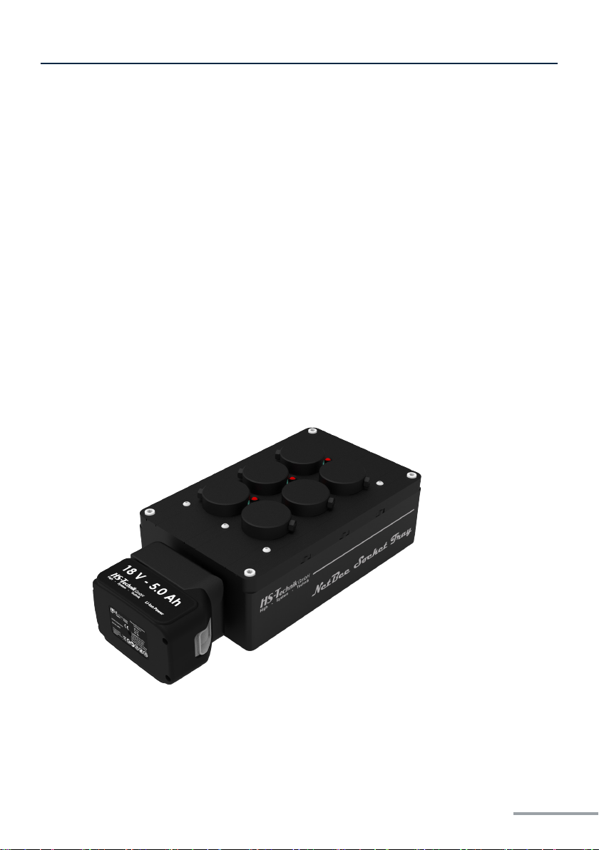
NetBee
- Original operang instrucons -
NetBee Socket Tray
Issue date: October 2022

- 2 -
1 Operang principles
1.1 Aim 3
1.2 NetBee Product Safety 4
1.3 Reference documents 4
1.4 Warranty Safety 4
2 Specicaons
2.1 Technical 5
2.2 Dimensions / Weight 6
2.3 Environmental 7
3 Funcon
3.1 Models 10
3.2 Equipment conguraon 11
3.3 Main parts 12
4 NetBee Socket Tray Conguraon
5 NetBee Socket Tray Maintenance
PAGE
3
PAGE
5
PAGE
8
PAGE
16
PAGE
19
Table of contents
- 3 -
1 Operang principles
Dear customers,
thank you for choosing a HS-Technik GmbH product.
This quality product „Made in Germany“ fulfils the highest requirements with regard to
performance, quality and accuracy. When used correctly the product will undoubtedly
perform very well for many years.
These operating instructions contain information on safety and for the operation of the
NetBee. In addition it contains information on the dimensions and technical data. We
would be happy to assist you with additional information or to answer your questions.
Our technical support and our technicians would be happy to assist you.
1.1 Aim
This manual is a complete guide for the NetBee Socket Tray, describing how to use.

- 4 -
1.2 NetBee Product Safety
WARNING
Before using the product, read the NetBee Socket Tray Product Safety
manual and strictly follow the safety instrucons.
1.3 Reference documents
To have a complete view of the NetBee Socket Tray applications, refer also the following
HS-Technik GmbH documents:
• NetBee Product Safety
• NetBee User Manual
1.4 Warranty Safety
Contact HS-Technik GmbH to claim a product. Warranty is applied only if the product has
been installed, operated and overhauled according to the instructions provided with the
product.
Please also see the delivery conditions applied by the HS-Technik GmbH.
- 5 -
2 Specicaons
2.1 Technical
Sockets
Depending from the model:
- 6 sockets, 39 mm
- 6 sockets, 50 mm
- 8 sockets, 39 mm
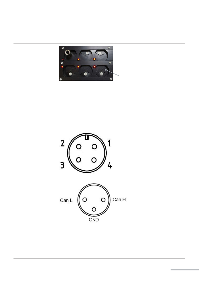
Power supply Models CANBUS and ETHERNET
The External power supply must be provided as following:
- Pin 3: +24VDC, maximum current 800 mA
- Pin 4: GND
Power Supply connector view from outside
Canbus connector view from outside
The mang connectors are delivered with the NetBee Socket Tray.
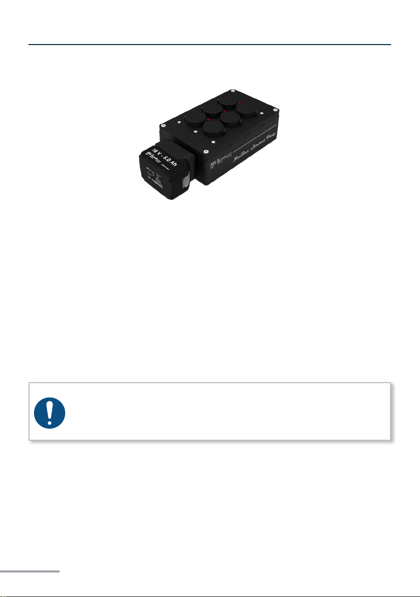
Models WiFi
Rechargeable baery (HST-PR-1850 18 V 5.0 Ah, Li-Ion)
for models WiFi. Baery last for at least 8 hours.
Sockets
- 6 -
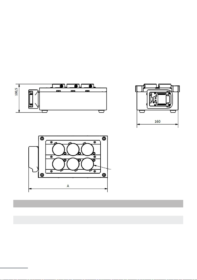
2.2 Dimensions / Weight
Dimensions are in millimeters. Customized NetBee Socket Tray versions may have
different dimensions.
NetBee Socket Tray WiFi
Model AWeight
NetBee-ST6-39-W 302 mm 4.0 kg
NetBee-ST6-50-W 302 mm 4.0 kg
NetBee-ST8-39-W 402 mm 5.2 kg
6/8 sockets
- 7 -
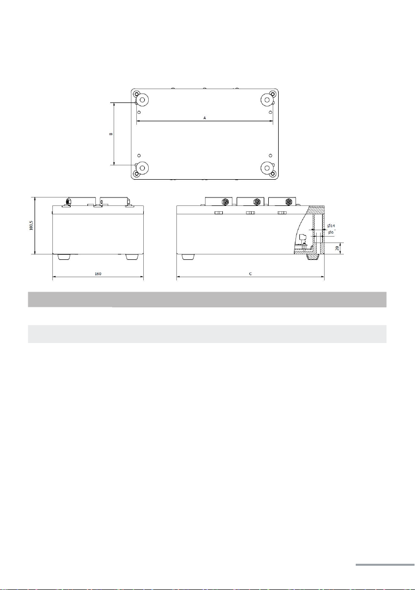
NetBee Socket Tray CANBUS / Ethernet
2.3 Environmental
The following condions must be observed during operaon:
• Internal Use only
• Environmental Class: II
• Ambient Temperature: 5 to 40°C
• Atmospheric humidity: 95%, non-condensing
• Altude: Up to 2000m
• IP grade: IP 40
Model A B C Weight
NetBee-ST6-39 240 mm 110 mm 260 mm 3.8 kg
NetBee-ST6-50 240 mm 110 mm 260 mm 3.8 kg
NetBee-ST8-39 340 mm 110 mm 360 mm 5.0 kg
- 8 -
3 Funcon
The NetBee Socket Tray is designed to manage the sockets used on tools and wrenches.
Operaon mode:
• All the sockets must be present on the tray.
• Only one socket must be taken at a me, according to the parameter (socket number) of
the ghtening operaon.
• If the wrong socket is taken, the ghtening operaon is not started.
NetBee
• NetBee denes the sequence of the assembly process, and checks that the operator
takes the correct socket from the tray
Refer to the NetBee user manual for more informaon.
NOTE
The NetBee Socket Tray does not start automatically a tightening operation
or a sequence when the socket is removed from the tray. NetBee starts the
operation and makes a check on the socket.

- 9 -
The NetBee Socket Tray connected to NetBee via WiFi
The NetBee Socket Tray connected via WiFi
The NetBee Socket Tray connected to NetBee via Ethernet
The NetBee Socket Tray connected via Ethernet
The NetBee Socket Tray connected to NetBee via Canbus

- 10 -
3.1 Models
The NetBee Socket Tray can be delivered in the versions:
WiFi: Wireless communication, working with:
• NetBee
Ethernet: Ethernet communication
• NetBee
Canbus: Canbus interface (for NetBee only), working with:
• NetBee
Sockets configuration can be:
• 6 sockets 39 mm
• 6 sockets 50 mm
• 8 sockets 39 mm
This manual suits for next models
3
Table of contents


