manuals.online logo
Brands
  1. Home
  2. •
  3. Brands
  4. •
  5. Vision
  6. •
  7. Accessories
  8. •
  9. Vision ZF 5201 IN User manual

Vision ZF 5201 IN User manual

Operation
1. While detecting water, the sensor will be triggered and send signal to your controller.
2. Normal operation, the LED will not light.
3. If the cover of sensor is removed, the tamper switch will send signal according the
Status/Signal table, and the LED will go solid. Before replacing the cover, the
sensor is under “Awake”mode.
Federal Communications Commission Statement
This equipment has been followed to comply with the limits for a Class B digital device,
pursuant to Part 15 of the FCC Rules. These limits are designed to provide reasonable
protection against harmful interference in a residential installation. This equipment
generates, uses and can radiate radio frequency energy and, if not installed and used in
accordance with the instruction, may cause harmful interference to radio communications.
However, there is no guarantee that interference will not occur in a particular installation.
If this equipment does cause harmful interference to radio or television reception, which
can be determined by turning the equipment off and on, the user is encouraged to try and
correct the interferene by one of the following measures:
-Reorient or relocate the receiving antenna,
-Increase the separation between the equipment and receiver,
-Connect the equipment into and outlet on a circuit different from that to
which the receiver is connected.
-Consult the dealer or an experienced radio/TV technician for help.
This device complies with Part 15 of the FCC Rules. Operation is subject to the following
two conditions: (1) this device may not cause harmful interference, and (2) this device
must accept any interference received, including interference that may cause undersired
operation.
FCC Caution: Any changes or modifications not expressly approved by the party
responsible for compliance could void the user’s authority to operate this equipment.
Limited Warranty
Vision Guarantees that every flood sensor is free from physical defects in material and
workmanship under normal use for one year from the date of purchase. If the product
proves defective during this one-year warranty period, Vision will replace it free of charge.
Vision does not issue any refunds. This warranty is extended to the original end user
purchase only and is not transferable. This warranty does not apply to : (1) damage to
units caused by accident, dropping or abuse in handling, or any negligent use; (2) units
which have been subject to unauthorized repair, taken apart, or otherwise modified; (3)
units not used in accordance with instruction; (4) damages exceeding the cost of the
product; (5) transit damage, initial installation costs, removal cost, or reinstallation cost.
For information on addional devices, plesae visit us at www.visionsecurity.com.tw
-3-
ZF5201
V0
1030319
6B1Z-52001
Installation & Operation Manual
ZF 5201 IN
ZF 5201 EU
ZF 5201 RU
ZF 5201 US
ZF 5201 IS
ZF 5201 JP
ZF 5201 BR
Flood Sensor
Introduction
Thanks for choosing the Vision’s flood sensor of the home security device. This sensor is a
Z-Wave™ enabled device (interoperable, two-way RF mesh networking technology) and is
fully compatible with any Z-Wave™ enabled network. AC powered Z-Wave enabled
devices act as a signal repeater and multiple devices result in more possible transmission
routes which helps eliminate “RF dead-sports”
Z-Wave™ enabled devices displaying the Z-Wave™ logo can also be used with it
regardless of the manufacturer, and ours can also be used in other manufacturer’s
Z-Wave™ enabled networks. This sensor sends Z-Wave™ signal while detecting water.
The sensor can be put under the refrigerator, and it will triggered while detecting the
leaking water. You can also install the sensor at anywhere it leaks; with this sensor you
can avoid loss before it flood.
Product Description and Specification
Specification:
Package Content:
Protocol: Z-Wave™ (ZM3102N)
Frequency Range:
865.22 MHz (ZF5201IN)
868.42MHz (ZF5201EU)
869.00 MHz (ZF5201RU)
908.42MHz (ZF5201US)
916.00MHz (ZF5201IS)
920.00 MHz (ZF5201JP)
921.42MHz (ZF5201BR)
Operating Range: Up to 100 feet line of sight
Operating Temp.: -15°C~ 60°C (5°F ~140°F)
1pc
1pc
1pcs
2pc
2pc
2pc
ZF 5201 sensor
CR123A Battery
Installation & Operation manual
Adhesive tape for main unit
Screws for bracket of main unit
Screws for sensor
Z-Wave Command Classes:
COMMAND_CLASS_ALARM_V2
COMMAND_CLASS_ASSOCIATION_V1
COMMAND_CLASS_BATTERY
COMMAND_CLASS_MANUFACTURER_SPECIFIC
COMMAND_CLASS_SENSOR_BINARY (mapping COMMAND_CLASS_BASIC)
COMMAND_CLASS_VERSION
COMMAND_CLASS_WAKE_UP_V2
-1-
Status/ Signal (Alarm report)
Alarm Type
Sensor be triggered
0x05
Back to original state
0x05
Cover opened
0x07
Alarm Event
Sensor be triggered
Ox02
Back to original state
0x02
Cover opened
0x03
Alarm Level
Sensor be triggered
0xFF
Back to original state
0x00
Cover opened
0xFF
Installation
Notice: If you install the entire Z-Wave™ system for the first time, please refer to the
installation guide of Z-Wave™ Interface Controller before installing ZF5201. For the first
time powers on, it will do auto-inclusion to the controller.
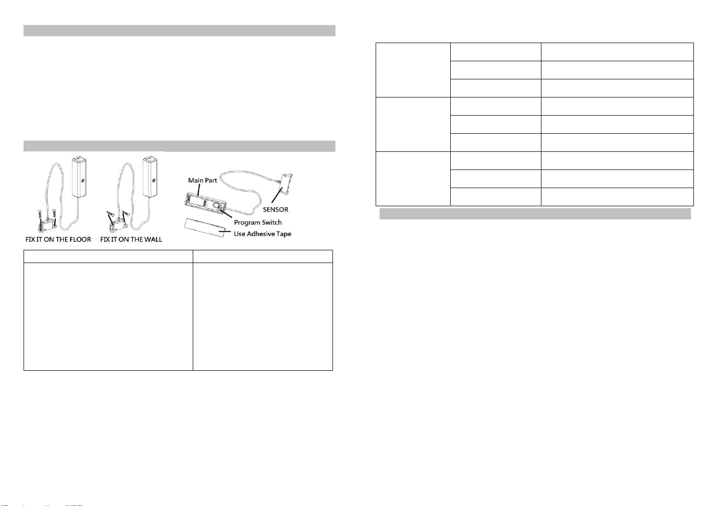
1. Fix the sensor on location you want, using the screws to fix it on the wall or floor.
2. Unscrew the screw fastening the rear cover and slide the rear cover down of main part and Insert a
CR123A battery into the battery compartment and LED will start to flash slowly, which means the
sensor has not yet been “inclusion”.
3. For “Inclusion”in (adding to) a network: Put the Z-Wave™Interface Controller into “inclusion”
mode, and following its instruction to add the ZF5201 to the controller. To get in the “inclusion”
mode, the distance between sensor and controller is suggested to be in one meter. Press the
program switch of ZF5201 for 1 second at least. The LED on the ZF5201 should go solid, if not,
please try again.
For “Exclusion” from (removing from) a network: Put the Z-Wave™ Interface Controller into
“exclusion” mode, and following its instruction to delete the ZF5201 from your controller. Press
the program switch of ZF5201 for 1 second at least to be excluded.
For “Association”: removing the cover of the ZF5201to get into the “Awake” mode, then put the
Z-Wave™ Interface Controller into “Association”, and following its instruction to associate the
ZF5201 with other device. Close the cover back after “association” done, afterward the ZF5201 will
get into “Sleep” mode for power saving. Support one association group (5 nodes).
”Awake” mode: it is to leave the “Sleep” mode by removing the cover of ZF5201, to allow the
Z-Wave™ Interface Controller to do “Inclusion”, “Exclusion”, “Association” and to reply and receive
the commands from controller.
4. Slide back the rear cover and screw fastening with the front cover of main part, the LED should go
off.
5. Put the main part at higher place for better RF range, and then use the adhesive tape to fix the
main part on the wall. -2-

This manual suits for next models

6

Other Vision Accessories manuals

Vision ZD2105IN-5 User manual

Vision

Vision ZD2105IN-5 User manual

Vision ZP3113IN-7 User manual

Vision

Vision ZP3113IN-7 User manual

Vision ZF 5201 IN-5 User manual

Vision

Vision ZF 5201 IN-5 User manual

Vision ZD2112IN-5 User manual

Vision

Vision ZD2112IN-5 User manual

Vision ZP3111IN-5 User manual

Vision

Vision ZP3111IN-5 User manual

Vision TC-HDMI12 User manual

Vision

Vision TC-HDMI12 User manual

Vision ZD2301IN-5 User manual

Vision

Vision ZD2301IN-5 User manual

Vision ZD 2102 EU User manual

Vision

Vision ZD 2102 EU User manual

Vision ZD 2102 EU User manual

Vision

Vision ZD 2102 EU User manual

Vision ZA1501IN-5 User manual

Vision

Vision ZA1501IN-5 User manual

Vision ZD2102IN-8 User manual

Vision

Vision ZD2102IN-8 User manual

Vision ZD2106IN-7 User manual

Vision

Vision ZD2106IN-7 User manual

Vision ZD2102IN-5 User manual

Vision

Vision ZD2102IN-5 User manual

Vision ZP3113IN-7 User manual

Vision

Vision ZP3113IN-7 User manual

Vision ZD2106IN-7 User manual

Vision

Vision ZD2106IN-7 User manual

Vision ZD2201IN-5 User manual

Vision

Vision ZD2201IN-5 User manual

Popular Accessories manuals by other brands

Mircom MIX-FC351AP Installation and maintenance instructions

Mircom

Mircom MIX-FC351AP Installation and maintenance instructions

Panasonic EX-F61 instruction manual

Panasonic

Panasonic EX-F61 instruction manual

Dynatron iKom operating instructions

Dynatron

Dynatron iKom operating instructions

Fishman Archtop Guitar Pickup user guide

Fishman

Fishman Archtop Guitar Pickup user guide

Reliable 6000FS instruction manual

Reliable

Reliable 6000FS instruction manual

FiT 501105 instruction manual

FiT

FiT 501105 instruction manual

Eshine ES960S user manual

Eshine

Eshine ES960S user manual

Mindfield eSense RESPIRATION Handbook

Mindfield

Mindfield eSense RESPIRATION Handbook

Ezviz T10 quick start guide

Ezviz

Ezviz T10 quick start guide

Giropes Baxtran TC15 user manual

Giropes

Giropes Baxtran TC15 user manual

Autonics BY Series product manual

Autonics

Autonics BY Series product manual

Elko iNELS Air AirCFS-100NB manual

Elko

Elko iNELS Air AirCFS-100NB manual

Viking FXI-1A product manual

Viking

Viking FXI-1A product manual

DYNATEK DSC-1 User instructions

DYNATEK

DYNATEK DSC-1 User instructions

SICK GLD20 operating instructions

SICK

SICK GLD20 operating instructions

IDW G-Series instruction manual

IDW

IDW G-Series instruction manual

NCTE 5000 Series manual

NCTE

NCTE 5000 Series manual

Kathrein ESD 64 manual

Kathrein

Kathrein ESD 64 manual

manuals.online logo
manuals.online logoBrands
  • About & Mission
  • Contact us
  • Privacy Policy
  • Terms and Conditions

Copyright 2025 Manuals.Online. All Rights Reserved.