manuals.online logo
Brands
  1. Home
  2. •
  3. Brands
  4. •
  5. HTW
  6. •
  7. Heat Pump
  8. •
  9. HTW LH5 Service manual

HTW LH5 Service manual

OWNER’S AND INSTALLATION
MANUAL
CASSETTE
Thanks for choossing our product.
Please, read carefully this manual
before using the product
ENGLISH
LH5
HTW-UO-052LH5 | HTW-UO-071LH5 | HTW-UO-105LH5
HTW-UOT3-140LH5 | HTW-UOT3-160LH5
HTW-C6I-052LH5 |HTW-C9I-071LH5 |HTW-C9I-105LH5
HTW-C9I-140LH5 |HTW-C9I-160LH5
Welcome to use our product!
Thanks for trusting us.
Please read this manual carefully before installation!
Keep it properly for future use after installation!
Features of This Air-Conditioner
The indoor unit can be installed inside the
ceiling conveniently.
High Efficiency and Environment Friendly
New Refrigerant-R410A*
R410A can protect the environment and do
not harm to the ozone layer.
24-hour Timer ON and OFF
This Timer can be set to automatically turn
the unit on or off within a 24-hour period.
Mute Operation
The excellent fan design enable the airflow
to be quiet and smooth with minimum noise.
Cassette
Save Installation Space Self Recovery of Power Break
When the power supply is recovered after
break, all preset are still effective and the air-
conditioner can run according to the original
setting.
Fault Self-diagnose Function
When there is something wrong with the air-
conditioner, the micro computer could
diagnose the faults, which can be read from
the display and is convenient for maintenance.
APPLICATION MODEL
*NOTE:
For
Cooling Only Unitary Air-conditioner, use referigerant
R22.
New DC Inverter Unitary Air-conditioner
(High-Efficiency Type)
HTW-C9-071LH5
HTW-C6-052LH5
HTW-C9-105LH5
HTW-C9T3-140LH5
HTW-C9T3-160LH5
● We pursue a policy of continuing improvement in design and performance of products. The
right is therefore reserved to vary specifications without notice.
● cannot anticipate every possible circumstance that might involve a potential hazard.
● This air conditioner is designed for standard air conditioning only. Do not use this heat
pump air conditioner for other purposes such as drying clothes, refrigerating foods or for any other
cooling or heating process.
● The installer and system specialist shall secure safety against leakage according to local regulations
or standards.
● No part of this manual may be reproduced without written permission.
● Signal words (DANGER, WARNING and CAUTION) are used to identify levels of hazard
seriousness. Definitions for identifying hazard levels are provided below with their respective signal
words.
Immediate hazards which WILL result in severe personal injury or
death.
Hazards or unsafe practices which COULD result in severe personal
injury or death.
Hazards or unsafe practices which COULD result in minor personal
injury or product or property damage.
Useful information for operation and/or maintenance.
● It is assumed that this heat pump air conditioner will be operated and serviced by English speaking
people. If this is not the case, the customer should add safety, caution and operating signs in the
native language.
● If you have any questions, contact your distributor or dealer .
● This manual gives a common description and information for this air conditioner which you operate
as well as for other models.
● This air conditioner has been designed for the following temperatures. Operate it within this range.
This manual should be considered as a permanent part of the air conditioning equipment and should
Remain with the air conditioning equipment.
We
IMPORTANT NOTICE
NOTE: Heating and electric heating function are not available for cooling only models.
New DC-Inverter Unitary ( )
High-Efficiency type DC-Inverter Unitary type(18 ,24 ,36K)
KK
DC-Inverter Unitary type(48K,60K)
ON/OFF Unitary type
Cooling Only Unitary type
outdoor working temperature(℃)
maximum minimum
Cooling Operation 48 -15
Heating Operation 24 -10
outdoor working temperature(℃)
maximum minimum
Cooling Operation 48 -15
Heating Operation 24 -10
outdoor working temperature(℃)
maximum minimum
Cooling Operation 43 15
Heating Operation 24 -10
outdoor working temperature(℃)
maximum minimum
Cooling Operation 43 15
Heating Operation 24 -10
outdoor working temperature(℃)
maximum minimum
Cooling Operation 43 15
CHECKING PRODUCT RECEIVED
● Upon receiving this product, inspect it for any shipping damage .Claims for damage, either
apparent or concealed, should be filed immediately with the shipping company.
● Check the model number, electrical characteristics (power supply, voltage and frequency) and
accessories to determine if they are correct.
The standard utilization of the unit shall be explained in these instructions.
Therefore, the utilization of the unit other than those indicated in these instructions is not
recommended.
Please contact your local agent, as the occasion arises.
Contents
Safety Precautions ---
Identification of Parts --------------------------------------------------------------------------------3
1. Wire Remote Controller Introduce -------------------------------------------------------------------5
2. Operation with Wire Remote Controller --------------------------------------------------------------7
2.1 mode function -------------------------------------------------------------------------------7
2.2 sleep function
--------------------------------------------------------------------------------8
2.3 timer function --------------------------------------------------------------------------------8
2.4 flap setting
-----------------------------------------------------------------------------------8
3.Wire Remote controller installation-------------------------------------------------------------------9
4.Wireless Remote Controller Introduce---------------------------------------------------------------10
4.1. Remote Controller-H1-----------------------------------------------------------------------10
operation mode-----------------------------------------------------------------------------12
airflow direction contro
l
---------------------------------------------------------------------13
smart mode -------------------------------------------------------------------------------14
clock button
-------------------------------------------------------------------------------14
timer mode --------------------------------------------------------------------------------15
sleep mode -------------------------------------------------------------------------------16
super mode
--------------------------------------------------------------------------------16
4.2. Remote controller-J1------------------------------------------------------------------------17
operation mode-----------------------------------------------------------------------------19
airflow direction control
---------------------------------------------------------------------20
smart mode
--------------------------------------------------------------------------------21
clock button
--------------------------------------------------------------------------------21
timer mode --------------------------------------------------------------------------------22
sleep mode
--------------------------------------------------------------------------------23
super mode
-------------------------------------------------------------------------------23
4.3. Remote controller-E4-07 --------------------------------------------------------------------24
operation mode-----------------------------------------------------------------------------26
airflow direction control
---------------------------------------------------------------------27
smart mode
--------------------------------------------------------------------------------28
clock button--------------------------------------------------------------------------------28
timer mode
---------------------------------------------------------------------------------29
sleep mode --------------------------------------------------------------------------------30
super mode
--------------------------------------------------------------------------------30
5. Before Operation
-------------------------------------------------------------------------------31
6. Special Remarks
--------------------------------------------------------------------------------31
7. Setting of Automatic Swing Louver -----------------------------------------------------------------31
8. Filter Cleaning
-----------------------------------------------------------------------------------32
9. Troubleshooting
---------------------------------------------------------------------------------33
-- -----------------------------------------------------------------------------1
Remote Controller Operation Manual
Contents
Diagram of Refrigerant Cycle
1.Refrigerant Flow Diagram ---------------------------------------------------------------34
2.Electrical Wiring Diagram ---------------------------------------------------------------34
-------------------------------------------------------- ---------------
------------------------------------------------- -
------------------------------------------------------
-------------------------------------------------------------------
( , , , ) ---------------------------------------------
( ) --------------------------------------------------------------
-------------------------------------------------------
-------------------------------------------------------------------
------------------------------------------------------------------------
-----------------------------------------------
----------------------------------------------------------------------
-------------------------------------------------------------------
----------------------------------------------------------
------------------------------------------------------------------------
----------------------------------------------------------------------
7.1 Ge ---------------------------------------------------------------------
---------------------------------------------------------
-------------------------------------------------------------------------------------
Installation and Maintenance
1. Safety Notice 35
2. The Tools and Instrument for Installation 36
3. The Installation of the Indoor Unit 36
3.1 The Initial Check 37
3.2 Installation for 24K 36K 42K 48K 60K 39
3.3 Installation for 18K 42
4. The Installation of the Outdoor Unit 44
4.1 The Initial Check 44
4.2 Installation 44
4.3Tuber Length between Indoor and Outdoor 45
5. Refrigerant Pipe 46
5.1 The Pipe Material 46
5.2 The Connection of the Piping 46
6. Drain Piping 48
7. Electrical Wiring 50
neral Check
ctrical Wiring Connection 51
53
-
-
--
,-
-
-
50
7.2 Ele -
8.Test Run ----------------------------------------------------------------------------52
9. Common -
Symbols in this User's Manual are interpreted as shown below:
Be sure not to do.
The feature of the appliance,
instead of a fault.
Pay attention to such a situation.
Grounding is necessary.
Be sure to follow the instruction.
Do not use the power supply circuit
breaker or pull off the plug to turn it off
during operation. This may cause a fire
due to spark, etc.
Keep the power supply circuit breaker
or plug from dirt. Connect the power
supply cord to it firmly and correctly,
lest an electric shock or a fire break out
due to insufficient contact.
Do not knit, pull or press the power supply
cord, lest the power supply cord be broken.
An electric shock or fire is probably caused
by a broken power supply cord.
Never insert a stick or similar to the unit.
Since the fan rotates at high speed, this
may cause an injury.
Do not repair the appliance by yourself.
If this is done incorrectly, it may cause an
electric shock, etc.
Turn off the appliance first before cutting
off power supply when malfunction occurs.
It is harmful to your health if the cool air
reaches you for a long time. It is advisable
to let the air flow be deflected to all the room.
Prevent the air flow from reaching the gas
burners and stove.
Do not touch the operation buttons
when your hands are wet.
It is the user's responsibility to make the
appliance be grounded according to
local codes or ordinances by a licenced
person.
OFF OFF
OFF
ON
ON ON
1
Warning: Incorrect handling could
cause a serious hazard, such as death,
serious injury,etc.
Used correct power supply in
accordance with the rating plate
requirement .
Otherwise, serious faults
may be occur or a fire may be break out
Safety Precautions
Features of protector Inspection
Noise pollution
Operating condition
The protective device maybe trip and stop
the appliance in the cases listed below:
HEATING
o
Outdoor air temperature is over 24 c
COOLING
DRY
o
Room temperature is over 27 c
o
Room temperature is below 21 c
o
Room temperature is below 18 c
If the air conditioner runs in "COOLING" or
"DRY" mode with door or window opened
for a long time when relative humidity is above
85%, dew may drip down from the air outlet.
The protective device will work at
following cases:
Stopping the appliance and restarting it
at once or changing mode during
operation, you need to wait 3 minutes.
After using for a long time , the air
conditioner should be inspected on
the following items:
Overheat of the power supply cord
and plug or even a burned smell.
Abnormal operating sound or vibration.
Water leakage from indoor unit.
Metal cabinet electrified .
Stop the air conditioner if above trouble
occurs.
It is advisable to have a detail inspection
after using it for 5 years even if none of
the above occurs.
Install the air conditioner at a place
that can bear its weight in order to
operate more quietly.
Features of HEATING modeFeatures of HEATING mode
Preheat
It is hard to raise the room temperature when outdoor temperature is very low. Use the air
conditioner together with other heating appliance in this case.
Defrost
At the beginning of HEATING operation, the airflow from indoor unit is discharged 2-5
minutes later.
In HEATING operation the appliance will defrost (de-ice) automatically to raise efficiency.
This procedure usually lasts 2-10 minutes. During defrosting, fans stop operation.
After defrosting completes, it returns to "HEATING" mode automatically.
Safety Precautions
2
Indoor unit
outdoor unit
Identification of Parts
3
Indoor unit
24K,36K,42K, 60K48K,
18K,24K,36K
18K
42K,48K,60K
Note:
Consequently, the shape may differ from that of the air conditioner you have selected.
This figure is based on the external view of a standard model.
The figures in this manual are based on the external view of a standard model.
Consequently, the shape may differ from that of the air conditioner you have selected.
Display Panel
Wire remote controller Wireless remote controller
Signal receiving section
Emergency switch
Defrost Filter Timer
Identification of Parts
4
18K
24K,36K, 48K,60K42K,
It lights on when timer is in use.
It rings when
.
the signal from
Remote controller is received
It lights on when the filter
should be cleaned.
The filter clean is resetted
if press the switch .
It lights on during the defrost.
It lights off when defrost finishes.
Receives signal from
the remote controller.
Timer indicator ( )
Green
buzzer
Filter clean ()Yellow
Emergency switch
Defrost indicator ( )Yellow
Signal receiving section
It lights on during operation.
It lights off all when setting
SLEEP mode.
Run indicator ( )RED
It lights off when timer finishes.
You can control the air-conditioner with the wire remote controller and wireless remote controller.
It is used for controlling power ON/OFF,
setting the running mode, temperature,
fan speed and other functions.
SET TEMP
ROOM
TEMP
C
AUTO
NO
.
TIMER ON
TIMER OFF
SET TIMER
A
It is used for controlling wire remote controller,
setting the running mode, temperature, fan
speed and other functions.
Note : The remote controller picked with indoor unit, please refer to the packing list .
If you need others, you may purchase it.
Optional remote control
FAN
MODE
TIMER ON
CLOCK
I
FEEL
TIMER OFF
SLEEP
SWING
SMART
SUPER
O
ON
OFF
ON/OFF
MODE FA N
SLEEP SUPER
SMART IFEEL DIMMER
TIMER ON TIMER OFF CLOCK
ON
OFF
SWING
SWING
ON
OFF
MODE
SMART
QUIET DIMMER
ECONOMY
FEEL
SUPER
FAN SPEED
CLOCK
TIMER ON
TIMER OFF
SLEEP
TEMP.
TEMP.
确定
1.Wire Remote Controller Introuce:
LCD screen
ROOM TEMP
TEMP. setting button
FAN speed/FLAP button
Room temperature sensor
ON/OFF button
MODE select button
TIMER/SLEEP button
Wireless remoter receiver
1 . Room temperature sensor:
A temperature sensor inside the wire remote control switch is set to sense room temperature, and the
temperature will be sent to indoor unit. When do not connect the wire remote control switch, indoor unit
will switch to the temperature sensor which is built into indoor unit.
2 . Wireless remoter receiver:
by this receiver, you can use a additional wireless remoter switch to control indoor unit.
3 . ON/OFF button:
press this button to turn on or turn off the unit.
4 . MODE select button:
Press this button to select COOLING, DEHUMIDIFICATION , FAN ,HEATING or AUTO-RUN mode.
COOLING mode, the air conditioner makes the room cool.
DEHUMIDIFICATION mode, the air conditioner reduces the humidity in the room.
FAN mode, the air conditioner makes the room's temperature suitable, providing the soft air flow.
HEATING mode, The air conditioner makes the room warm.
5 . TIMER/SLEEP button:
“”
.
Press this button to active sleep mode, and will appear in LCD. Press again to cancel sleep function.
Press this button for 3 seconds to active timer function, Press for 5 seconds again to cancel timer function.
To timer function Pls. refer to timer function introduce
AUTO
C
“” “”
“” “”
“”
“” “”
6 . FAN speed button:(Flap button setting refers to description page 8.)
Press this button to change current fan speed. You can select (auto fan speed), (low fan
speed), (medium fan speed), and (high fan speed) by each press.
7 . TEMP Setting button:
Press the couple of buttons to set room temperature you want, when you press SET TEMP sign will
appear in LCD, press button to reduce setting temperature, and press button to increase
setting temperature.
Wire Remote Controller
5
AUTO-RUN mode, The air conditioner runs in right mode according to the temperature of room.
(This mode is invalid for high-energy efficiency s .
18k,24k DC Inverter Unitary air-conditioners except type )
A
SET TEMP
ROOM
TEMP
C
AUTO
NO
.
TIMER ON
TIMER OFF
SET TIMER
Display room temperature
and setting temperature
Running state sign area Which
indicate the running state
Fan speed display
8 .LCD screen
Flap direction display (Only for embedded
type unit)
Mode indication area Which indicate
the current running mode
Display timer setting
Operation mode
cooling mode
dehumidification mode
fan mode
heating mode
18k,24k DC
Inverter Unitary air-conditioners except
type )
auto mode
(This mode is invalid for
high-energy efficiency s .
Fan speed setting
Flap direction display
auto fan
high fan speed
swing sign
meddle fan speed
low fan speed
Temperature display
Room temperature:
Setting temperature:
ROOM
TEMP
C
SET TEMP
C
AUTO
A
TIMER ON
TIMER OFF
timer on
timer clock
timer off
Outdoor is defrosting
Compressor is running
Soft running mode is active
Sleep mode is active
A
A
Wire Remote Controller
6
2.Operation with Wire Remote Controller
1.Press MODE button to select operation mode:“”
A
cooling mode
dehumidification mode
fan mode
heating mode
auto-run mode
(This mode is invalid for
high-energy efficiency s .
18k,24k DC Inverter Unitary air-conditioners
except type )
2. Press ON/OFF button to turn on or turn off the unit
3. Press TEMP. SETTING button to set room temperature. The temperature
range can be set from 18℃ to 32℃。
4. Press FAN button to set fan speed you want. Of course you can set auto fan and indoor
unit will automatic select fan speed according to the difference between room temperature and
setting temperature
“”
“”“”
“”
5. You may turn off the unit by press ON/OFF button again
Note:In fan mode, temperature setting is invalid.
“”
2.1 mode function
Wire Remote Controller
7
2.2 sleep function
ROOM TEMP
C
Press timer/sleep button once to active sleep function. And sleep
sign“ ”will appear on LCD.
Press timer/sleep button again to cancel sleep function, and sleep
sign on LCD will disappear.
Note:
During fan mode, the sleep function is invalid.
auto mode,
IF the air conditioner is on, press the“ ”for
seconds,“trickle”a sound, Then the flap begin swing.
IF you need stop swing,press the“ ”for two seconds
again,and the flap stop swing.
two
2.3 Timer function
2.4 Flap setting
ROOM TEMP
C
TIMER OFF
TIMER OFF mode
1 you can set timer off when indoor unit is running. By press
TIMER/SLEEP button for 3 seconds, timer clock appear on
LCD, and “TIMER OFF”flag will twinkle.
2 you can adjust the time after which the indoor unit would turn
off automatically by press “ ”“ ” button. The time can
be set from 0.5 to 24(or 12) hour in 30 minutes steps.
3 when you have set the time, press TIMER/SLEEP button for
3 seconds again
“TIMER OFF”flag will
4 IF you need cancel “TIMER OFF”,press TIMER/SLEEP
button for 3 seconds to active the timer, Press “ ”“ ”
button set time 00:00,Cancel “TIMER OFF”after five
seconds automatically.
or wait for 5 seconds to active the timer,
stop twinkle, and timer begin to work.
ROOM TEMP
ROOM TEMP
C
C
TIMER ON
TIMER ON
TIMER ON mode
1 you can set timer on when indoor unit is shut off, By press
TIMER/SLEEP button for 3 seconds, timer clock appear on
LCD, and “TIMER ON” flag will twinkle.
2 you can adjust the time after which the indoor unit would turn
on automatically by press “ ”“ ” button. The time
can be set from 0.5 to 24(or 12) hour in 30 minutes steps.
3 when you have set the time, press TIMER/SLEEP button
for 3 seconds again to active the timer,
“TIMER ON” flag will stop twinkle, and timer begin to work.
4 IF you need cancel “TIMER ON”,press TIMER/SLEEP
button for 3 seconds to active the timer, Press “ ”“ ”
button set time 00:00,Cancel “TIMER ON”after five
seconds automatically.
or wait for 5 seconds
Timer clock
Wire Remote Controller
8
Installation of the wire remote controller please refer to the following:
The wire remote controller must be installed by qualified installation technicians in accordance
with installation drawing instruction, the power should be shut off before installation. Air flow and
away from heating where the wire remote controller is installed. The following is process of
installation.
1 .Insert a minus screw driver into down slot (2 places).
Be careful not to damage the PC board with minus screw driver.
2 .Remove the back cover.
3 .Use two screw(φ4×16) to fasten the back and metal board in the mounting place and tighten
the screw, then link the communication wire.
4 .Fasten top cover into back cover.
5 .Fasten bottom cover into back cover.
ire 3.W Remote Controller Installation
Wire Remote Controller
9
The remote controller transmits signals to the system.
-H1
Remote controller
10
1
2
4
3
13
12
5
6
11
7
8
9
10
SUPER BUTTON
SWING BUTTON
FAN BUTTON
ROOM TEMPERATURE
SETTING BUTTONS
SLEEP BUTTON
DIMMER BUTTON
CLOCK BUTTON
ON/OFF BUTTON
SMART BUTTON
MODE BUTTON
TIMER ON/OFF BUTTON
Used to start or stop the fast cooling.
(Fast cooling operates at high fan speed with
18℃ set temp automatically)
Used to stop or start adjustment
louver swinging and set the desired up/down
airflow direction.
horizontal
SWING BUTTON
Used to stop or start adjustment
louver swinging and set the desired left/right
airflow direction.
vertical
Used to select fan speed in sequence
auto, high, medium or low.
Used to set or cancel Sleep Mode operation.
The screen brightness is decreased each time
that button is pressed and it goes blank after
pressing the button four times.
Used to set the current time.
Used to enter fuzzy logic operation directly,
regardless of the unit is on or off.
The appliance will be started when it is
energized or will be stopped when it is
in operation, if you press this button.
Press this button to select the operation mode.
Used to set or cancel the timer operation.
Remote controller
Indication symbols on LCD:
Used to adjust the room temperature and
the timer, also real time.
10 11
12
13
3
4
1
2
6
7
5
8
9
MODE
CLOCK
TIMER ON TIMER OFF
DIMMER
SMART
SWING
SWING MUTE
TEP SWITCH
SLEEP
I FEEL
SOFT
14
16
17
15
18*
14 MUTE BUTTON
Used to . set or cancel Mute mode operation
16
I FEEL BUTTON
Used to start or stop the I feel mode. Press this
button above 5 seconds , Turn off I FEEL mode.
(In I feel mode,the Air Conditioner operates basis
temperature sensor fitted in remote instead of machine,
Advice to use I FEEL mode and the remote put
where the indoor unit receive signal easily.)
15
TEP SWITCH BUTTON
Display set temperature flickeringly when the button is
pressed. Display indoor temperature when the button
is pressed again. And the flicker must be closed by
pressing the button or cutting off the electricity supply.
17
18*
SOFT BUTTON
Used to limit the maximum electric current,so that
you can use it with other electric instrument when
power is not enough.
(invalid for heating mode)
Note: Each mode and relevant function will be further specified in following pages.
Signal transmit.
Dry indicator
Fan only indicator
Heating indicator
Cooling indicator
High fan speed
Medium fan speed
Low fan speed Display set temperature
Display set timer
Display current time
Auto fan speed Smart indicator
Sleep indicator
Mute indicator
Super indicator
Soft indicator Cancel I feel indicator
(invalid for this model)
( only effective for DC inverter model)
*Some remote controller models without this button.
How to Use
11
To operate the room air conditioner, aim
the remote controller to the signal receptor.
The remote controller will operate the air
conditioner at a distance of up to 8m when
pointing at signal receptor of indoor unit.
Remote controller
Remote controller
MODE
CLOCK
TIMER ON TIMER OFF
DIMMER
SMART
MUTE
TEP SWITCH
SLEEP
I FEEL
SOFT
How to Insert the Batteries
Remove the battery cover according to the arrow direction.
Insert new batteries making sure that the (+) and (-) of
battery are matched correctly.
Reattach the cover by sliding it back into position.
Note:
Use 2 LR03 AAA(1.5volt) batteries. Do not use rechargeable batteries.
Replace batteries with new ones of the same type when the display
becomes dim.
SWING
SWING
SET TEMP
ROOM
TEMP
C
AUTO
NO.
TIMER ON
TIMER OFF
SET TIMER
A
R
RUN TIMER FILTER
DEFROST
18K
24K,36K,42K, 60K48K,
Each time MODE button is pressed, the operation mode
is changed in sequence:
Each time the "FAN" button is pressed, the fan speed is
changed in sequence:
18℃~32℃
Heating mode is NOT available for cooling only air conditioner.
HEATING
COOLING DRY FAN ONLY
Selecting mode
FAN mode
Auto High Medium Low
At "FAN ONLY" mode, only "High","Medium" and "Low" are available.
At "DRY" mode, Fan speed is set at "Low" automatically, "FAN" button
is ineffective in this case.
Setting temperature
Press once to temperature setting by 1lower ℃
Press once to temperature setting by 1raise ℃
Range of available set temperature
*HEATING, COOLING
SWING, SMART, TIMER ON, TIMER OFF, CLOCK, SLEEP and SUPER operation modes will be
specified in the following pages.
Changing modes during operation, sometimes the unit does not response at once. Wait 3 minutes.
Wait 3 minutes before restarting the appliance.
During heating operation, air flow is not discharged at the beginning. After 2-5 minutes, the air flow will be discharged
until temperature of indoor heat exchanger rises.
Operation instructions
12
Operation modes
Note: Heating mode is NOT available for cooling only models.
MODE
CLOCK
TIMER ON TIMER OFF
DIMMER
SMART
MUTE
TEP SWITCH
SLEEP
I FEEL
SOFT
1
3
2
SWING
SWING
Do not turn the horizontal adjustment louvers manually, otherwise malfunction may occur. If that happens,
turn off the unit first and cut off the power supply, then restore power supply again.
It is better not to let the adjustment louver tilt downward for a long time at COOLING or DRY mode to prevent
condensed water from dripping.
horizontal
Operation instructions
13
Airflow direction control
MODE
CLOCK
TIMER ON TIMER OFF
DIMMER
SMART
MUTE
TEP SWITCH
SLEEP
I FEEL
SOFT
4
4
SWING
SWING
4
Airflow direction control
Horizontal vertical and airflow is automatically adjusted to a certain
angle in accordance with the operation mode after turning on the unit.
The direction of airflow can be
also adjusted to your own
requirement by pressing the
" " and the " "
button of the remote controller.
Operation mode Direction of airflow
COOLING, DRY
*HEATING,
FAN ONLY
horizontal
downward
SWING SWING
Vertical airflow control (with the remote controller)
Using remote controller to set various angles of flow or specific angle
as you like.
Swinging airflow
Pressing " " button once, the adjustment
louver will swing up and down automatically.
horizontal
Desired direction airflow
Pressing the " " button again when the louvers swing
to a suitable angle as desired.
Horizontal airflow control (with the remote controller)
Using remote controller to set various angles of flow or specific angle
as you like.
Swinging airflow
Pressing " " button once, the vertical adjustment
louver will swing left and right automatically.
Desired direction airflow
Pressing the " " button again when the louvers swing
to a suitable angle as desired.
SWING
SWING
SWING
SWING
Note: invalid for cassette type.Vertical airflow control is
SMART button is ineffective in SUPER mode.
Press the SMART button, the unit enters SMART mode(fuzzy logic operation) directly regardless of
the unit is on or off. In this mode, temperature and fan speed are automatically set based on the
actual room temperature.
Note: Temperature, airflow and direction are controlled automatically in SMART mode.
However, a decrease or rise of up to 7 ℃ can be set with the remote controller if you still
feel uncomfortable.
Operation instructions
14
SMART mode
Indoor temperature
Indoor temperature
Target temperature
Target temperature
Below T-3℃
Over T+3℃
T+3℃ or below
T
T
T
T
T
Over T+3℃
T-3℃T+3℃
≦Tindoor≦
Operation mode
Operation mode
HEATING
FAN ONLY
FAN ONLY
COOLING
COOLING
Operation mode and temperature are determined by indoor temperature
Heat pump models
Cooling only models
CLOCK button
You can adjust the real time by pressing CLOCK button, then
using and buttons to get the correct time, press
CLOCK button again the real time is set.
MODE
CLOCK
TIMER ON TIMER OFF
DIMMER
SMART
MUTE
TEP SWITCH
SLEEP
I FEEL
SOFT
SWING
SWING
Your feeling
What you can do in SMART mode
button adjustment procedure
Uncomfortable
because of
unsuitable air
flow volume.
Uncomfortable
because of
unsuitable flow
direction.
Uncomfortable
because of
unsuitable flow
direction.
Indoor fan speed alternates among
High, Medium and Low each time this
button is pressed.
Press it once, the adjustment
louver swings to change vertical airflow
direction. Press it again, swings stops.
horizontal
Press it once, the adjustment
louver swings to change horizontal airflow
direction. Press it again, swings stops.
vertical
SWING
SWING

This manual suits for next models

10

Other HTW Heat Pump manuals

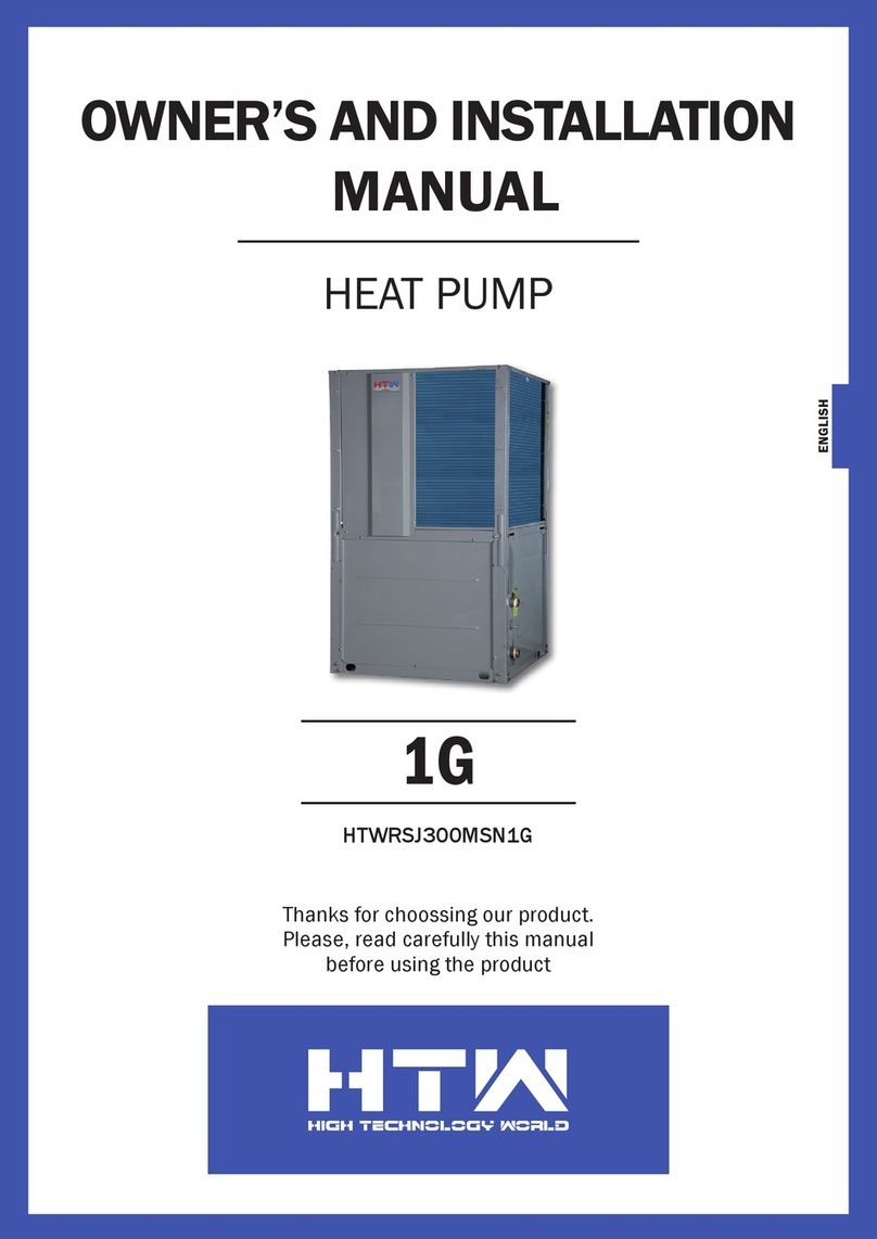
HTW 1G Service manual

HTW

HTW 1G Service manual

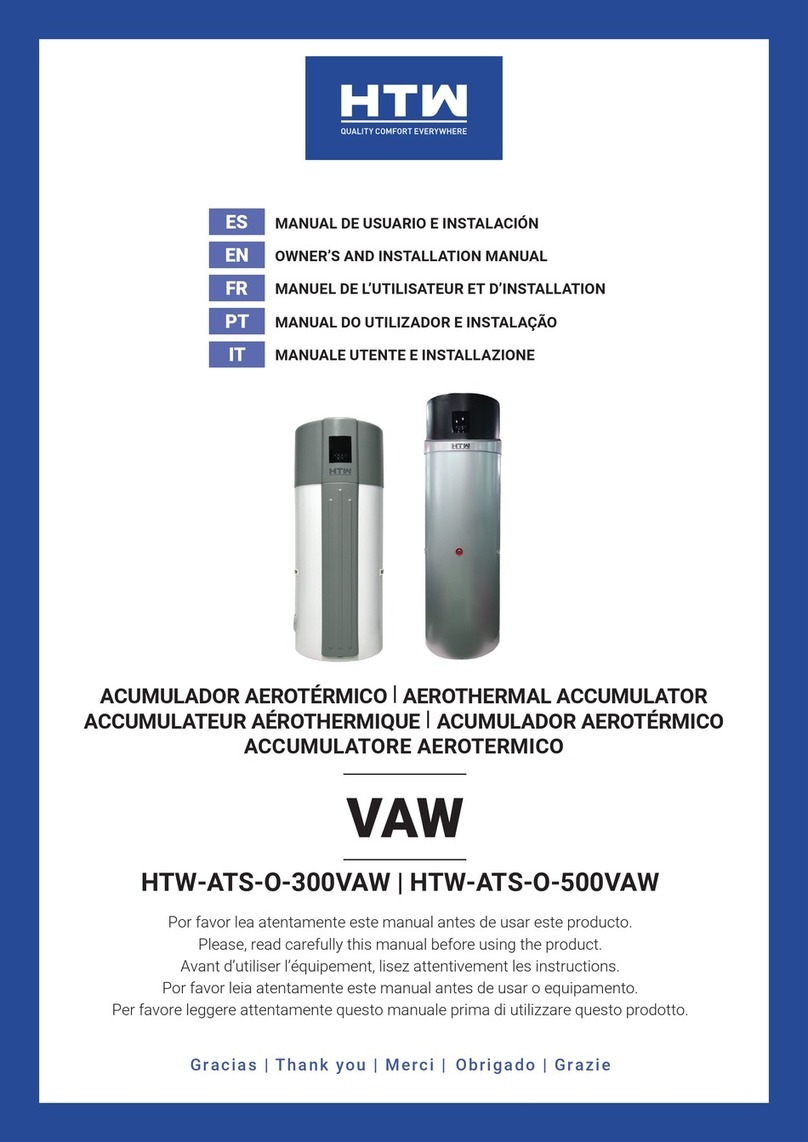
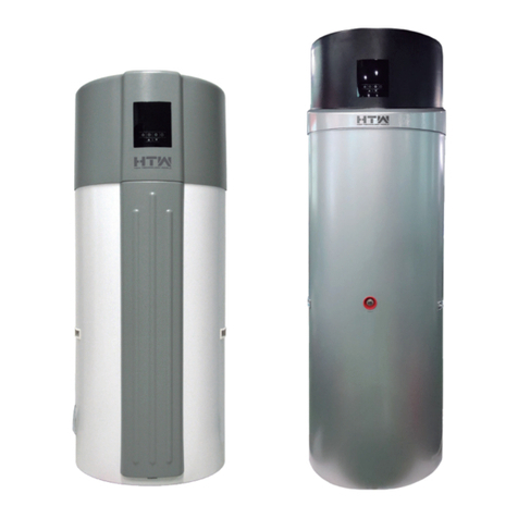
HTW VAW HTW-ATS-O-300VAW Service manual

HTW

HTW VAW HTW-ATS-O-300VAW Service manual

HTW ECO-THERMAL PLUS HTW-V18WD2RN8PLUS User manual

HTW

HTW ECO-THERMAL PLUS HTW-V18WD2RN8PLUS User manual

HTW RSJ Series Service manual

HTW

HTW RSJ Series Service manual

HTW VAX Service manual

HTW

HTW VAX Service manual

HTW VAX HTW-ATS-O-500VAX Service manual

HTW

HTW VAX HTW-ATS-O-500VAX Service manual

HTW VAW Series Service manual

HTW

HTW VAW Series Service manual

HTW VAW 100L Service manual

HTW

HTW VAW 100L Service manual

HTW LION HTW-SWP-O-070LIO Service manual

HTW

HTW LION HTW-SWP-O-070LIO Service manual

Popular Heat Pump manuals by other brands

Carrier bryant 607E K Series installation instructions

Carrier

Carrier bryant 607E K Series installation instructions

Carrier 38YCG Series Product data

Carrier

Carrier 38YCG Series Product data

Daikin FTXM-V Series Service manual

Daikin

Daikin FTXM-V Series Service manual

Kronoterm WP2 LF-202S Instructions for use and installation

Kronoterm

Kronoterm WP2 LF-202S Instructions for use and installation

andrews HPAC 90 Operating instructions  & safety guide

andrews

andrews HPAC 90 Operating instructions & safety guide

auer HTi70 6 Installation and user manual

auer

auer HTi70 6 Installation and user manual

iDM iPump A 3-11 Technical documentation installation instructions

iDM

iDM iPump A 3-11 Technical documentation installation instructions

Daikin FNQ25A2VEB installation manual

Daikin

Daikin FNQ25A2VEB installation manual

Vaillant geoTHERM VWS operating manual

Vaillant

Vaillant geoTHERM VWS operating manual

Bryant 607B User's information manual

Bryant

Bryant 607B User's information manual

Daikin ETSH16P30EF User reference guide

Daikin

Daikin ETSH16P30EF User reference guide

STIEBEL ELTRON WPL 07 ACS classic Operation and installation

STIEBEL ELTRON

STIEBEL ELTRON WPL 07 ACS classic Operation and installation

Dimplex WI 22 TE Installation and operating instructions

Dimplex

Dimplex WI 22 TE Installation and operating instructions

Lennox HP21 Unit information

Lennox

Lennox HP21 Unit information

Riello NexPro Series INSTRUCTIONS FOR THE INSTALLER AND FOR THE TECHNICAL ASSISTANCE CENTRE

Riello

Riello NexPro Series INSTRUCTIONS FOR THE INSTALLER AND FOR THE TECHNICAL ASSISTANCE CENTRE

Daikin RXR28EV1B9 Service Manual Removal Procedure

Daikin

Daikin RXR28EV1B9 Service Manual Removal Procedure

Nibe AP-BW30 operating manual

Nibe

Nibe AP-BW30 operating manual

Sanyo KHS1822 Submittal sheet

Sanyo

Sanyo KHS1822 Submittal sheet

manuals.online logo
manuals.online logoBrands
  • About & Mission
  • Contact us
  • Privacy Policy
  • Terms and Conditions

Copyright 2025 Manuals.Online. All Rights Reserved.