Nibe F2015 User manual

INSTALLATION AND MAINTENANCE INSTRUCTIONSMOS GB 1008-3
F2015
031239 F2015
LEK


For Home Owners
General
System description
Principle of operation 3
Maintenance routines
General 4
For the Installer
General points for the installation engineer
Transport and storage 5
Inspection of the installation 5
Assembly 5
Control 5
Pipe connections
General 6
Pipe coupling heating medium circuit 6
Water volumes 6
Pressure drop, heating medium side 6
Docking
General 7
Abbreviations 7
F2015 docked with VVM 300 (fixed condensing) 7
F2015 docked to the oil-fired/pellet boiler together with SMO
10 and water heater (floating condensing) 8
Several F2015 together with SMO 10 and water heater (floating
condensing) 9
F2015 docked to an electric/oil boiler (floating condens-
ing) 10
F2015 docked with wood fired boiler and hot water heater
(fixed condensing) 11
Electrical connections
General 13
Connection 13
Charge pump 14
Anti-freeze function 14
External heat cable 14
Outside sensor 14
Thermostat control 15
Additional heat / Downtime 15
Example of addition connection 15
External indication of main alarm 15
Commissioning and adjusting
Preparations 16
Filling and venting the heating medium system 16
Balance temperature 16
Stop temperature 16
Soft-start relay 16
Compressor heater 16
Start-up and inspection 17
Readjusting, heating medium side 17
Adjustment, charge flow 18
Control
Explanation 20
Channel descriptions 21
Control conditions, cold outdoor air 23
Control conditions defrosting 23
Sensor placement
Temperature sensor data 24
Data for discharge sensor 24
Miscellaneous
Electrical circuit diagram
1x230V 6-11 kW 25
Technical specifications
Component positions 29
Sound pressure levels 31
Dimensions and setting-out coordinates 32
Technical specifications 33
Enclosed kit 35
Accessories 35
Dealing with malfunctions
Checking the status 36
F2015 is not operational 36
Draining, heat medium side 37
1F2015
Table of Contents

General
In order to get the greatest benefit from your heat pump F2015 you should read through the For Home Owners section in this
Installation and Maintenance Instruction.
F2015 is a basic heat pump for heating small houses, apartment blocks and small industrial premises. Outdoor air is used as a
heat source.
F2015 is a Swedish-made quality product offering a long life span and reliable operation.
Serial number* (103), must always be stated in all correspondence with NIBE.
______________
Installation date
Type designation
F2015-____
Installation engineers
Setting
Factory settingChannel
1...........................................Communications addressA1
48 °C...........................................Max return temperatureA2
4°C...........................................Connection diff. return temp.A3
20 min...........................................Start interval compressorA4
+5 °C...........................................Balance temperatureA5
120 min...........................................Time delay addition relayA6
-15 °C...........................................Stop temperatureA7
see page 22...........................................Min. interval between defrostingA8
0°C...........................................Start defrostingA9
+10 °C...........................................Stop defrostingA10
7 min...........................................Longest defrostingA11
Any changes in the basic settings are noted here.
Datum__________________________ Sign___________________________
*See "Component positions" page 29 for location of the serial number.
This appliance is not intended for use by persons (including children) with reduced physical, sensory or mental capabilities, or lack of experience and
knowledge, unless they have been given supervision or instruction concerning use of the appliance by a person responsible for their safety.
Children should be supervised to ensure that they do not play with the appliance.
Rights to make any design or technical modifications are reserved.
©NIBE 2010.
F20152
For Home Owners
General

System description
Principle of operation
F2015 is an air/water heat pump, specially designed for the
Nordic climate. F2015 utilises the outside air so there is no
need for bore holes or coils in the ground. F2015 has an
automatic 2-stage capacity control of the fan (does not apply
to F2015-6 kW, which only has one fan speed).
F2015 is designed for **water based heating systems and
can be used together with most electric boilers, oil-fired
boilers or equivalent. The heat pump includes an advanced
control system for optimal control. F2015 is started by a start
signal from another controller or thermostat.
F2015 can also be controlled by a specially designed control-
ler, SMO 10 *. This connects and disconnects the additional
heat and controls switching between room heating and hot
water heating.
Accessories such as extra shunt group and pool control can
be connected if SMO 10 is present.
F2015 can both heat hot water effectively at high outdoor
temperatures and give a high output to the heating system
at low outdoor temperatures.
If the outdoor temperature drops to a level below the stop
temperature all heating must then occur with external addi-
tional heat.
F2015 is manufactured in three sizes: 6, 8 and 11 kW.
The material has been chosen for a long service life.
FIGHTER 2020
VVM 300
AV
AV
SÄV
SF
RC
TV
UG
)
990
accessory for F2015*
When docking with F2015, a total water volume, incl.
boiler, radiators, pipes, etc. of at least 20 litres boiler water
per kW output on the heat pump is recommended.
**
The heating medium side and the hot water side must be
fitted with the necessary safety equipment in accordance
with the applicable regulations.
3F2015
For Home Owners
System description

Maintenance routines
General
F2015 is equipped with control and monitoring equipment,
however some exterior maintenance is still necessary.
Make regular checks throughout the year that the inlet grille
is not clogged by leaves, snow or anything else. Check, dur-
ing the cold months of the year, to make sure that there isn't
a build up of ice or frost under F2015. The Condensation
water trough KVT 10 accessory is available for management
and removal of condensation. Strong wind combined with
heavy snowfall can block the intake and exhaust air grilles.
Make sure that there is no snow on the grilles.
If necessary the outer casing can be cleaned using a damp
cloth. Care must be exercised so that the heat pump is not
scratched when cleaning. Avoid spraying water into the grilles
or the sides so that water penetrates into F2015. Prevent
F2015 coming into contact with alkaline cleaning agents.
!WARNING!
Rotating fan
F20154
For Home Owners
Maintenance routines

General points for the installation engineer
Transport and storage
F2015 should be transported and stored vertically.
Inspection of the installation
Current regulations require the heating installation to be in-
spected before it is commissioned. The inspection must be
carried out by a suitably qualified person and should be
documented. The above applies to closed heating systems.
If the heat pump is replaced, the installation must be inspec-
ted again.
Assembly
F2015 is placed outdoors on a firm base, preferably a con-
crete foundation. F2015 should not be positioned next to
sensitive walls, for example, next to a bedroom. Also ensure
that the placement does not inconvenience the neighbours.
Care must be exercised so that the heat pump is not
scratched during installation.
Large amounts of condensation water as well as melt water
from defrosting can be produced. Provide good drainage at
the installation area and make sure water cannot run out
onto paths or the like during periods that ice can form. Ideally
condensation water is led off to a drain or similar. It is also
possible to install the accessory KVT 10, which is a collecting
trough for leading off condensation.
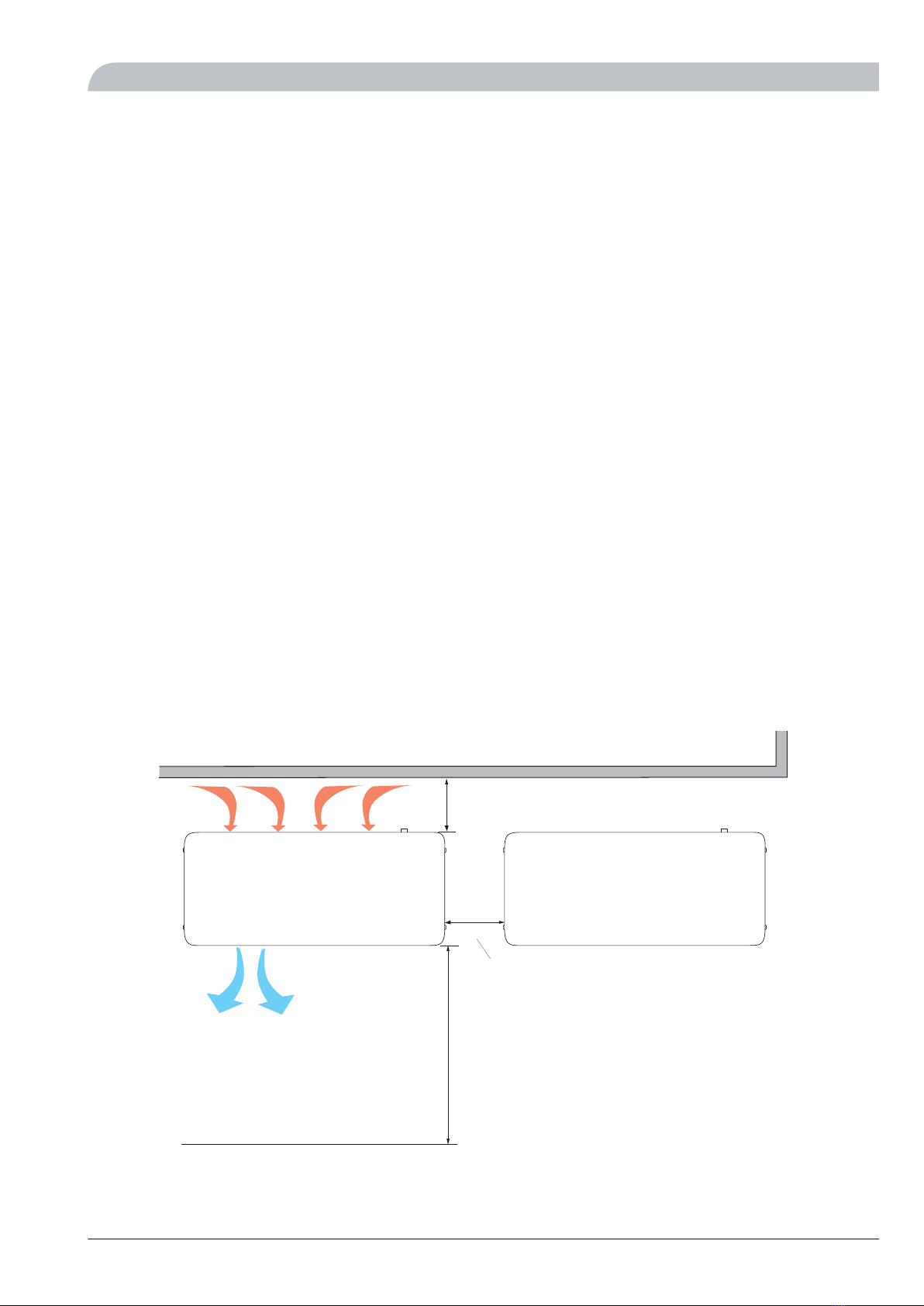
The distance between F2015 and the house wall must be at
least 350 mm. Clearance in front of F2015 should be at least
one metre. F2015 must not be placed so that recircula-
tion of outdoor air can occur. This causes lower output
and impaired efficiency.
Control
F2015 is equipped with an internal electronic controller that
handles all functions necessary for heat pump operations.
Accordingly, defrosting, stop at max/min temperature, con-
nection of the compressor heater as well as enabling the
heater for the drip pan, monitoring of motor protection and
pressure switches are controlled.
The number of starts and the operating time can also be
read.
The integrated controller is set during installation and can
be used during a service.
Under normal operation conditions the home owner does
not need to have access to the controller.
F2015 has an integrated electronic return line sensor that
limits the return temperature.
F2015 can also be switched on/off via signals from other
control equipment or a thermostat. If F2015 is controlled
from the accessory SMO 10 the control is described in the
instructions supplied.
SMO 10 communicates with F2015 which means that set-
tings and measurement values from F2015 can be adjusted
and read off in SMO 10 .
350 mm
400 mm
3 m
Fritt utrymme bakom
Fritt utrymme framför
Fritt utrymme
Min. avstånd
vid användning
av flera F 2025
)UHH VSDFH
)UHH VSDFH EHKLQG
)UHH VSDFH LQ IURQW
0LQ GLVWDQFH ZKHQ XVLQJ VHYHUDO )
5F2015
For the Installer
General points for the installation engineer

Pipe connections
General
Pipe installation must be carried out in accordance with cur-
rent norms and directives.
F2015 operates up to a return temperature of about 50 °C
and an outgoing temperature of about 58 °C from the heat
pump. Because F2015 is not equipped with shut off valves
these must be installed outside the heat pump to facilitate
any future servicing. The return temperature is limited by the
return line sensor and is adjusted on channel A2.
NOTE
The pipe work must be flushed before the heat pump
is connected, so that any contaminants do not damage
the components parts.
Pipe coupling heating medium circuit
F2015 can be connected to the heating system, see the
"Docking" section or one of the system solutions that can
be downloaded from the website www.nibe.eu.
The heat pump must be vented by the upper connection (70,
HM-out) using the venting nipple on the enclosed flexible
hose.
The supplied particle filter (SF) must be installed before the
inlet, i.e. the lower connection (71, HM-in) on F2015. All
outdoor pipes must be thermally insulated with at least
19 mm thick pipe insulation.
The charge pump must be operational, even if F2015
is not running, to prevent damage due to freezing.
The charge pump can also be controlled directly from F2015,
terminal block (11), which takes the outdoor temperature
into consideration. Alternatively, the heat pump is connected
to an intermediate circuit with a heat exchanger, pump and
water with anti-freeze.
Shutoff (AV) and drain valves (TV) are fitted so that F2015
can be emptied in the event of prolonged power failures.
The supplied flexible hoses act as vibration dampers. The
flexible hoses are fitted so a slight bend is created, thus acting
as vibration damping.
Water volumes
When docking with F2015, a total water volume, in the
boiler and accumulator, of at least 20 litres boiler water per
kW output on the heat pump is recommended.
Pressure drop, heating medium side
F2015 -6, 8, 11
0
1
2
3
4
5
6
7
8
9
0 0,10 0,20 0,30 0,40 0,50 0,60 0,70
kPa
Tryckfall
6 kW 8, 11 kW
Flöde
l/s
3UHVVXUH GURS
)ORZ
OV
N3D
L
+HDW LQVXODWLRQ
F20156
For the Installer
Pipe connections

Docking
General
F2015 can be installed in several different ways. The requisite
safety equipment must be installed in accordance with cur-
rent regulations for all docked options.
See www.nibe.eu for more docking options.
When docking with F2015, a total water volume, in the
boiler and accumulator, of at least 20 litres boiler water per
kW output on the heat pump is recommended.
Abbreviations
Shut-off valveAV
Circulation pumpCP1
Included in SMO 10Temperature sensor, flow pipeFG1
Auxiliary relayHR
Charge pumpLP
Included in SMO 10Return temperature sensorRG1
Control valveRV
Included in F2015Particle filterSF
Shunt valveSV
Safety valveSÄV
Drain valveTV
Outside sensorUG
Heating thermostatVT
Hot water sensorVVG
F2015 docked with VVM 300 (fixed condensing)
FIGHTER 2020
VVM 300
AV
AV
SÄV
SF
RC
TV
UG
)
990
F2015 -6, -8 and -11 can be connected to VVM 300. F2015
is controlled by VVM 300. F2015 works with floating con-
densing against the heating system and prioritises hot water
charging in VVM 300.
If F2015 cannot meet the heating requirement, additional
heat is shunted in from VVM 300. If the outdoor temperat-
ure drops below the set stop temperature, VVM 300 en-
gages and takes over heating.
NOTE
To prevent interference, sensor cables and communic-
ation cables must be separated (min 20 cm) from high
voltage cables when cable routing.
7F2015
For the Installer
Docking

F2015 docked to the oil-fired/pellet boiler together with SMO 10 and water heater (floating con-
densing)
VXV1
PG
SMO 10
HR
HR
HR
HR
SF RV
P
FG1 CP1
RG1
SV1
VVG
LP1
UG
SÄV
FIGHTER 2020
)
SMO 10 controls F2015, oil-fired boiler, circulation pumps,
shunts, etc. F2015 works with floating condensing against
the heating system and prioritises hot water charging via the
three way valve (VXV1).
If F2015 cannot meet the heating requirement, the oil-fired
boiler is started and additional heat is shunted in.
NOTE
To prevent interference, sensor cables and communic-
ation cables must be separated (min 20 cm) from high
voltage cables when cable routing.
F20158
For the Installer
Docking

Several F2015 together with SMO 10 and water heater (floating condensing)
HR
HR
HR
FIGHTER 2020 VP2
FIGHTER 2020 VP1
SV1 FG1
RG1
SMO 10
CP1
PG
UG
LP2
LP1
VVG
VXV1
P
SÄV
SÄV
SÄV
AV
AV BV
BV
RV
TV
RV
TV
BV
SF
SF
) +3
) +3
SMO 10 controls up to nine F2015 (of which max one for
hot water), immersion heater, circulation pump, shunt, etc.
F2015 works with floating condensing against the heating
system and prioritises hot water charging via three way valve
VXV1. F2015 VP1 produces hot water.
If F2015 cannot meet the heating demand, additional heat
is shunted in from the oil-fired boiler.
When additional heat is engaged, hot water is heated using
the immersion heater in the hot water heater.
NOTE
To prevent interference, sensor cables and communic-
ation cables must be separated (min 20 cm) from high
voltage cables when cable routing.
9F2015
For the Installer
Docking

F2015 docked to an electric/oil boiler (floating condensing)
P
FIGHTER 2020
AV
RV LP
SF
SƒV
TV
RT 10
RC
Extern alt
befintlig regler-
utrustning.
)
([WHUQDO RU H[LVWLQJ
FRQWURO HTXLSPHQW
F2015 is controlled by a room thermostat. F2015 works with
floating condensing on the return from the heating system.
If F2015 cannot meet the heating requirement the additional
heat is shunted in using the existing control equipment.
Additional heat can be blocked above the set balance tem-
perature by means of the automatic control system in F2015.
In other cases the heat pump does not collaborate with the
electric/oil fired boiler in the optimum way.
Hot water production only takes place using the existing
electric/oil boiler.
This option requires accessory RT 10.
F201510
For the Installer
Docking

F2015 docked with wood fired boiler and hot water heater (fixed condensing)
FIGHTER 2020
AV
RVSF
SÄV
TV
VT
BV
LP1
UG
RC
Vedpanna
Extern alt
befintlig regler-
utrustning.
VVB / ACK
)
([WHUQDO RU H[LVWLQJ
FRQWURO HTXLSPHQW
:RRGILUHG ERLOHU
99%$&.
F2015 charges the water heater/accumulator tank (VVB/ACK).
When the firewood boiler is in use, the heat pump and im-
mersion heater are disconnected when the temperature rises
on the thermostat (VT) and start again when the temperature
drops.
Self-circulation through the heat pump is prevented by the
check valve (BV).
11F2015
For the Installer
Docking

Electrical connections
NOTE
Electrical installation and service must be carried out
under the supervision of a qualified electrician. Electric-
al installation and wiring must be carried out in accord-
ance with the stipulations in force.
NOTE
The live external control must be taken into considera-
tion when connecting.
,QFRPLQJ VXSSO\
LEK
Incoming feed cable is supplied and factory connected to
terminal block -X1. Approx. 1.8 m cable is accessible outside
the heat pump.
F201512
For the Installer
Electrical connections

General
The routing of cables for heavy current should be made out
through the cable glands on the heat pump's left-hand side,
seen from the front (100) and signal cables from the rear
(102).
Connection
႑A heat pump must not be connected without the permis-
sion of the electricity supplier and must be connected
under the supervision of a qualified electrician.
႑If a miniature circuit breaker (MCB) is used this should
have motor characteristic “D” (compressor operation).
For MCB size see "Technical Specifications".
႑F2015 does not include an omnipolar circuit breaker on
the incoming power supply. The heat pump’s supply cable
must be connected to a circuit-breaker with at least a 3
mm breaking gap. When the building is equipped with
an earth-fault breaker the heat pump should be equipped
with a separate one. Incoming supply must be 230 V 1AC
50Hz via distribution boards with fuses.
႑If an insulation test is to be carried out in the building,
disconnect the heat pump.
႑Connect control signal cable for thermostats to terminal
(30). Cable type: unscreened LiYY, screened LiYCY. Cable
area, at least 0.22 mm² with cable lengths less than 50
m.
႑Alternatively the relevant signal cable is connected from
terminal (44) on the control card (34) to SMO 10/VVM
300.
႑Charge pump for F2015 can be connected to terminal
block (11) or to separate supply.
Note! If F2015 is deenergized and the charge pump
is connected to the terminal block (11) there is a risk
of freezing.
႑A common alarm can be connected to terminal (11).
LEK
1 mm
5,5 mm
LEK
13F2015
For the Installer
Electrical connections

Charge pump
When the charge pump is connected to the terminal block
X11 (11) terminal 3 and 4 the pump is controlled by F2015.
Pump activity is dependent on the status of F2015, heat-
ing/hot water requirement and the outdoor temperature.
Pump exercising is handled by F2015.
Anti-freeze function
At temperatures below +2 °C, the charge pump runs period-
ically, and at temperatures below -20 °C it runs continually.
This function applies on the condition that F2015 is powered.
35
30
25
20
15
10
5
5 4 3 2 1 0 -1 -2 -3 -4 -5 -6 -7 -8 -9 -10 -11 -12 -13 -14 -15 -16 -17 -18 -19 -20 -21 -22 -23 -24 -25
0
0LQXWHV SHU PLQXWHV
7HPSHUDWXUH
NOTE
There is a risk of freezing when the charge pump is
connected to terminal block X11 (11) and F2015 is
deenergized.
FIGHTER 2020EXTERNT
Signal vid icke larm
Signal vid larm
Laddpump
Extern värmekabel
NN
230
V
3
4
1
X11
2
5
6
11
)
(;7(51$/
6LJQDO RQ
QRQDODUP
6LJQDOV LQ WKH
HYHQW RI DODUPV
&KDUJH SXPS
([WHUQDO KHDW
FDEOH
LEK
External heat cable
F2015 is equipped with a terminal block for the Condensation
water trough KVT 10 accessory. Max load is 200 W.
Outside sensor
An outdoor sensor (15) is located on the underside of F2015.
F201514
For the Installer
Electrical connections

NOTE
The following pages about thermostats, additional
heat, common alarms and downtime, do not apply
when F2015 is controlled by SMO 10/VVM 300.
Thermostat control
You can use a basic thermostat or a closing potential-free
contact to switch the compressor on and off. This thermostat
should be of the breaking type (NC) when the set temperat-
ure has been reached. The contactor should be potential
free.
Connection of the single step thermostat is made as set out
in the picture below.
3
4
1
X200
2
Termostat
30
)
(;7(51$/
7KHUPRVWDW
Additional heat / Downtime
F2015 is equipped with a potential free contactor intended
for additional heat. Max 250V 2A.
The setting of the outdoor temperature (balance temperature)
when the additional relay is activated is made on channel
A5, see the section “Control - Channel description”.
External additional heat: connected via the additional relay
terminal X201 (14).
Conditions for connecting additional heat:
႑the outdoor air temperature should be lower than the
set balance temperature (channel A5).
႑The compressor must have been operating for the minim-
um period that can be set in channel A6. Defrosting is
included in this time.
If the outdoor air temperature drops down to a level below
the set value, stop temperature (downtime), in channel A7,
compressor operations are blocked and all heating must take
place using the external additional heat via the downtime
relay terminal X201 (14). This function is also activated when
F2015 is deenergized.
If the outdoor temperature exceeds 35 °C compressor oper-
ation is blocked and downtime is activated.
The connection to the additional relay is made as set out in
the picture below.
FIGHTER 2020EXTERNT
3
4
5
6
1
X201
Tillsatsvärme
Stillestånd
NO
NC
COM
NO
NC
COM
2
14
)(;7(51$/
$
GGLWLRQDO KHDW
'RZQWLPH
Max load across the relay contactors is 250V 2A.
During operations without the need of the additional heat
or downtime the relay contactors are closed between NO
and COM.
Additional heat and downtime are acquired between NC
and COM.
The contactors are drawn in the deenergized state.
Additional and downtime relays are activated during normal
operating conditions for F2015. Both relays are deactivated
in the event of operating disruptions.
Example of addition connection
Basic electrical circuit diagram for connection of auxiliary re-
lays for additional heat and downtime.
NO O/C
NC
Hjälpkontaktor
12 – 230V
$X[LOLDU\ FRQWDFWRU
QRW VXSSOLHG
&20
External indication of main alarm
F2015 is equipped with a contactor for external indication
of common alarms. The function becomes active with all
types of existing alarms. Max. load across the relay contactors
is 250V 2A.
Make the connection for external indication of the main
alarm as set out in the figure below:
FIGHTER 2020EXTERNT
Signal vid icke larm
Signal vid larm
Laddpump
Extern värmekabel
NN
230
V
3
4
1
X11
2
5
6
11
)
(;7(51$/
6LJQDO RQ
QRQDODUP
6LJQDOV LQ WKH
HYHQW RI DODUPV
&KDUJH SXPS
([WHUQDO KHDW
FDEOH
15F2015
For the Installer
Electrical connections

Commissioning and adjusting
Preparations
Before commissioning, check that the heating circuit is filled
and well vented. Check the pipe system for leaks.
Filling and venting the heating medium system
The heating medium system is filled with water to the re-
quired pressure. Vent the system using the venting nipple
on the enclosed flexible hose and possibly the circulation
pump.
9HQWLQJ QLSSOH
Balance temperature
The balance temperature is the outdoor temperature when
the heat pump’s stated output is equal to the building’s
output requirement. This means that the heat pump covers
the whole building’s output requirement down to this tem-
perature. Setting of the balance temperature, additional heat,
is made on channel A5.
Stop temperature
When the stop temperature (channel A7) is set between -7
and -15 °C the flow temperature is limited linearly from -7 °C
/ 55 °C to -15 °C / 45 °C.
Soft-start relay
F2015 is equipped with a soft-start relay (97) that limits the
inrush current for the compressor.
The compressor must not be forced to start with periods
shorter than 1 start per 15 minutes.
Compressor heater
F2015 is equipped with a compressor heater that heats the
compressor before start-up and when the compressor is cold.
The compressor heater must have been connected for6-8
hours before the FIRST start, see the section “Start-up and
inspection”.
NOTE
The compressor heater must have been connected for
6 – 8 hours before the first start, see the section “Start-
up and inspection”.
F201516
For the Installer
Commissioning and adjusting

Start-up and inspection
1. Communication cable (44) or thermostat, plinth (30)
must not be connected.
2. Turn the isolator switch on.
3. Ensure that the F2015 is connected to the power source.
4. Check that the miniature circuit-breaker (2) is on.
5. The compressor heater (25) must have been operational
for at least6–8hours before the compressor start can
be initiated. This is done by switching on the control
voltage and disconnecting the communications cable or
thermostat.
6. The display on the control card (34) shows C0/CC F0
H1/H3 depending on the outdoor temperature. During
this period the compressor is heated to increase the
service life.
7. The communication cable or external thermostat is con-
nected after 6 – 8 hours. See the section “Electrical
connection” – “Thermostat control”.
8. Restart the SMO 10/VVM 300.
9. Once the connection is made, the compressor starts after
approx. 20 minutes if needed.
10. Adjust the charge flow according to the diagram, see
the section "Adjustment, charge flow"
11. Fill in the commissioning report on page 2.
NOTE
The live external control must be taken into considera-
tion when connecting.
LEK
Readjusting, heating medium side
Air is initially released from the hot water and venting may
be necessary. If bubbling sounds can be heard from the heat
pump, the circulation pump and radiators the entire system
will require further venting. When the system is stable (correct
pressure and all air eliminated) the automatic heating control
system can be set as required.
17F2015
For the Installer
Commissioning and adjusting

Adjustment, charge flow
Adjusting the temperature difference (ΔT) between the flow
temperature and the return temperature during hot water
charging or at high load.
This is easily done by using the temperatures measured in
Channel T2 (flow temperature) less Channel T3 (return tem-
perature), this temperature difference (ΔT) is adjusted using
circulation pump and control valve. Adjustment is performed
with stable operation about 5 minutes after start, or about
5 minutes after defrosting with a cold outdoor temperature.
The temperature difference must be as in the diagram below
(+1- 2 K). At outdoor temperatures above 28 °C the charge
flow can be increased by 30 % to obtain a lower ΔT.
The diagrams show the heat pump with a high fan speed,
at low fan speeds ΔT will be 0.5 to 1 degrees lower (does
not apply to F2015-6 kW, which only has one fan speed).
1 flow temperature. 35°
2 flow temperature. 45°
3 flow temperature. 55°
F2015-6
2
3
4
5
6
7
8
9
10
11
12
-15 -10 -5 0 5 10 15 20 25 30
1
2
3
1
2
3
2
4
6
8
10
12
14
16
18
20
22
-
15
-
10
-
5 0 5 1015202530
1
2
3
ΔT
Phase current, A
Specified output, kW
Outdoor temperature Outdoor temperature
Rated output
Phase current
F2015-8
2
4
6
8
10
12
14
-15 -10 -5 0 5 10 15 20 25 30
1
2
3
3
2
1
2
4
6
8
10
12
14
16
18
-15 -10 -5 0 5 10 15 20 25 30
1
2
3
ΔT
Phase current, A
Specified output, kW
Outdoor temperature Outdoor temperature
Rated output
Phase current
F201518
For the Installer
Commissioning and adjusting
Table of contents
Other Nibe Heat Pump manuals
Popular Heat Pump manuals by other brands

Dometic
Dometic Duo-Therm 59116.502 Installation & operating instructions

HIdRos
HIdRos LZT P2U Series Technical manual

York
York MILLENNIUM YCUL0045SC Installation operation & maintenance

Carrier
Carrier PHJ4 Owner's information manual

Viessmann
Viessmann Vitocal 200-S Installation and service instructions

Glen Dimplex
Glen Dimplex LAW 9IMR Installation and operating instruction