Huaptec F10-GDW User manual

1
F10-GDW
Triple Systems

2
Table of contents
How it works ...................................................................................3
Package contents..........................................................................4
Install your hardware....................................................................5
Troubleshooting...........................................................................14
Specifications...............................................................................15
Product Warranty.........................................................................16
Safety Warnings ..........................................................................16

3
How it works
Huaptec F10-GDW is designed to help mobile users to amplify
weak 2G and 3G signals. Huaptec amplifiers are bi-directional. The
donor antenna receives the signals from a cell tower, amplifies
them and transmits to the signal booster. Then the indoor antenna
receives the signals and retransmits them to your mobile device.
The signals produced by your phone are amplified by the indoor
antenna via the booster and donor antenna.

4
Package contents
Optional antenna kits
We will provide all accessories needed for the signal booster.
For more information please visit www.huaptec.eu
Triple Systems
Signal booster
Outdoor panel
antenna
Omni ceiling
antenna
Power supply
12V/7A
RF cable
Indoor panel
antenna
YAGI antenna
Whip antenna
Waterproof tape

5
Install your hardware
Before you install
1 Make sure you have sufficient cable length between
donor/server antenna location and boosterconnector.
2 Make sure the place where you install the booster is well
ventilated, near to electrical outlet, and away from excessive
heat, moisture and direct sunlight.
Installation overview
1 Install your donor antenna on the roof where signal reception
is the strongest.
2 Mount your signal booster, attach the cables from the outside
antenna and inside antenna to the signal booster at the
designated ports, and connect the booster to the AC supply
(make sure all the cables are well connected).
3 Install the indoor antenna in the area where you want to
improve the signal.

6
Find the area with the strongest signal
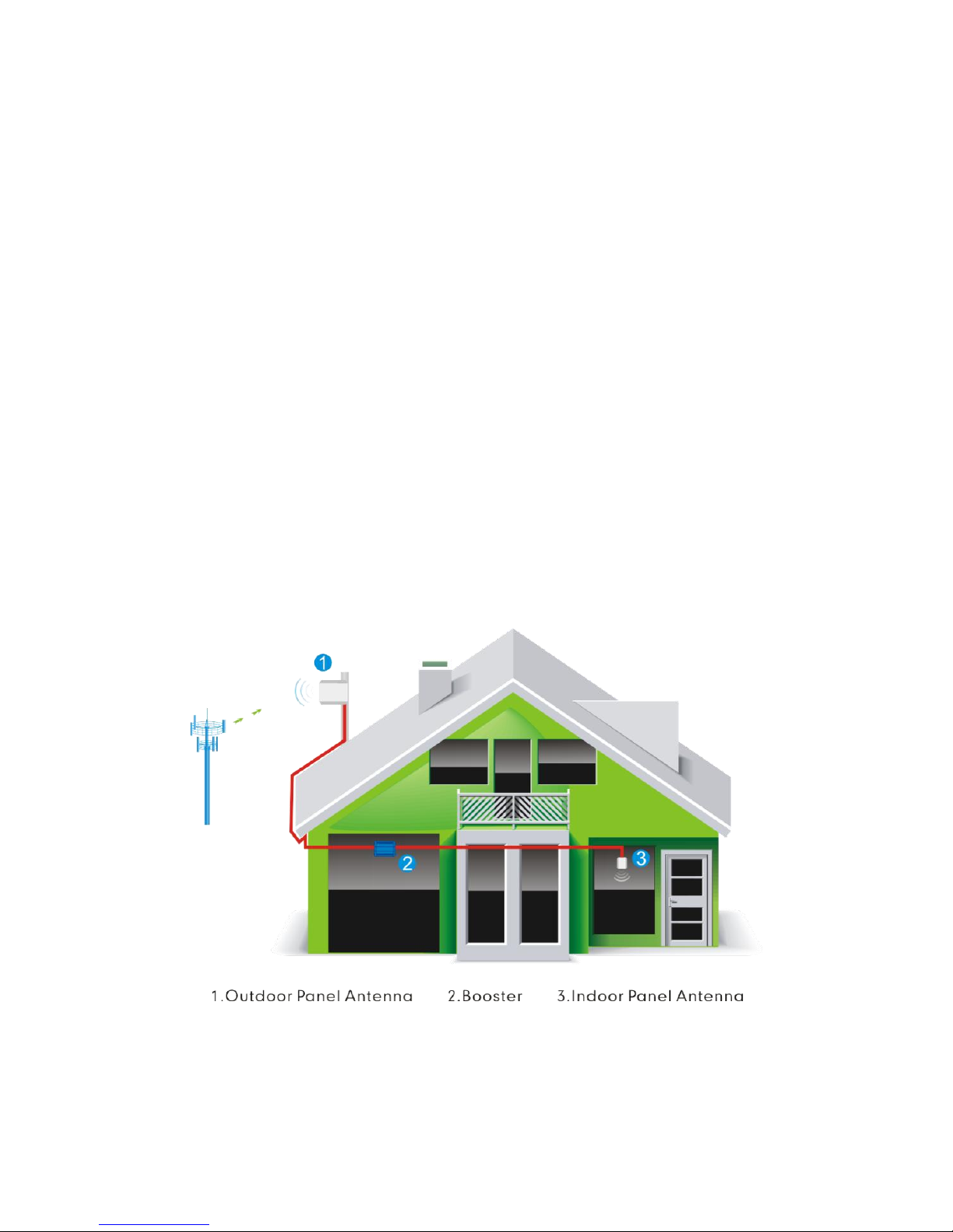
The booster’s main function is to improve weak RF signals in a
certain area. The signal strength from the outdoor antenna directly
affects the efficiency of the indoor coverage.
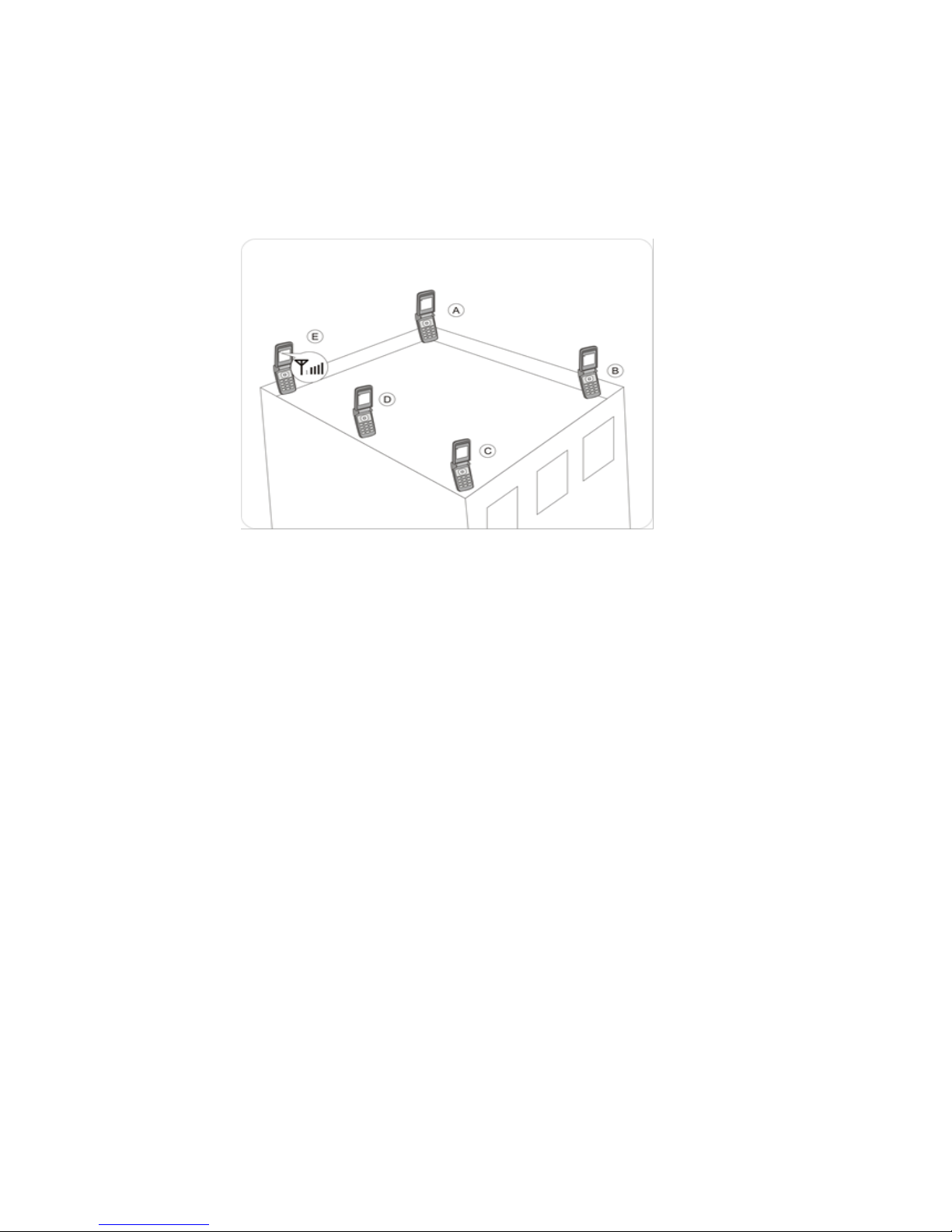
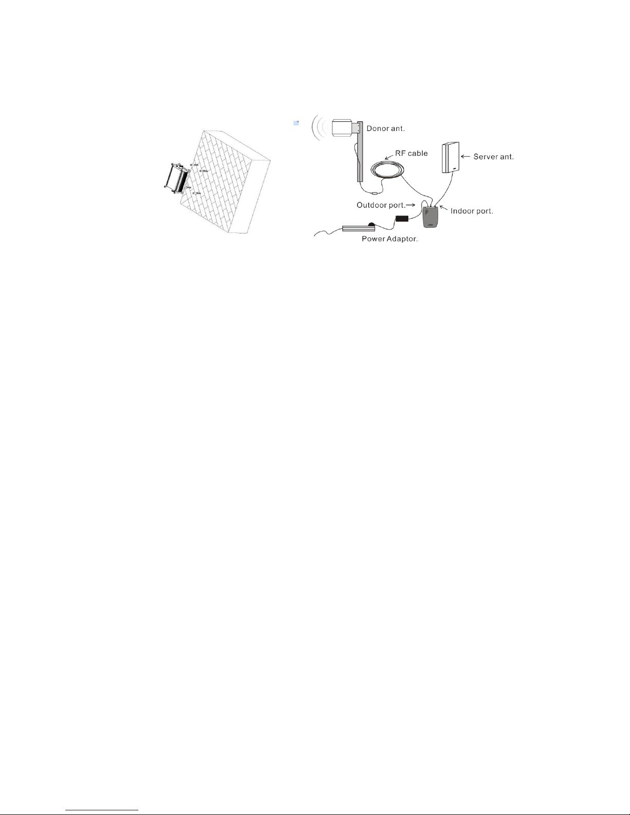
Install the Outdoor Antenna
Select a proper place to install the donor antenna.
Normally a roof of the building is a good choice. As shown
from the above graph, you need to test the signal from A to E
and select a point with best signal for installation.
Choose the direction for the donor antenna.
The donor antenna should point to the base mobile tower to
get stronger signals.
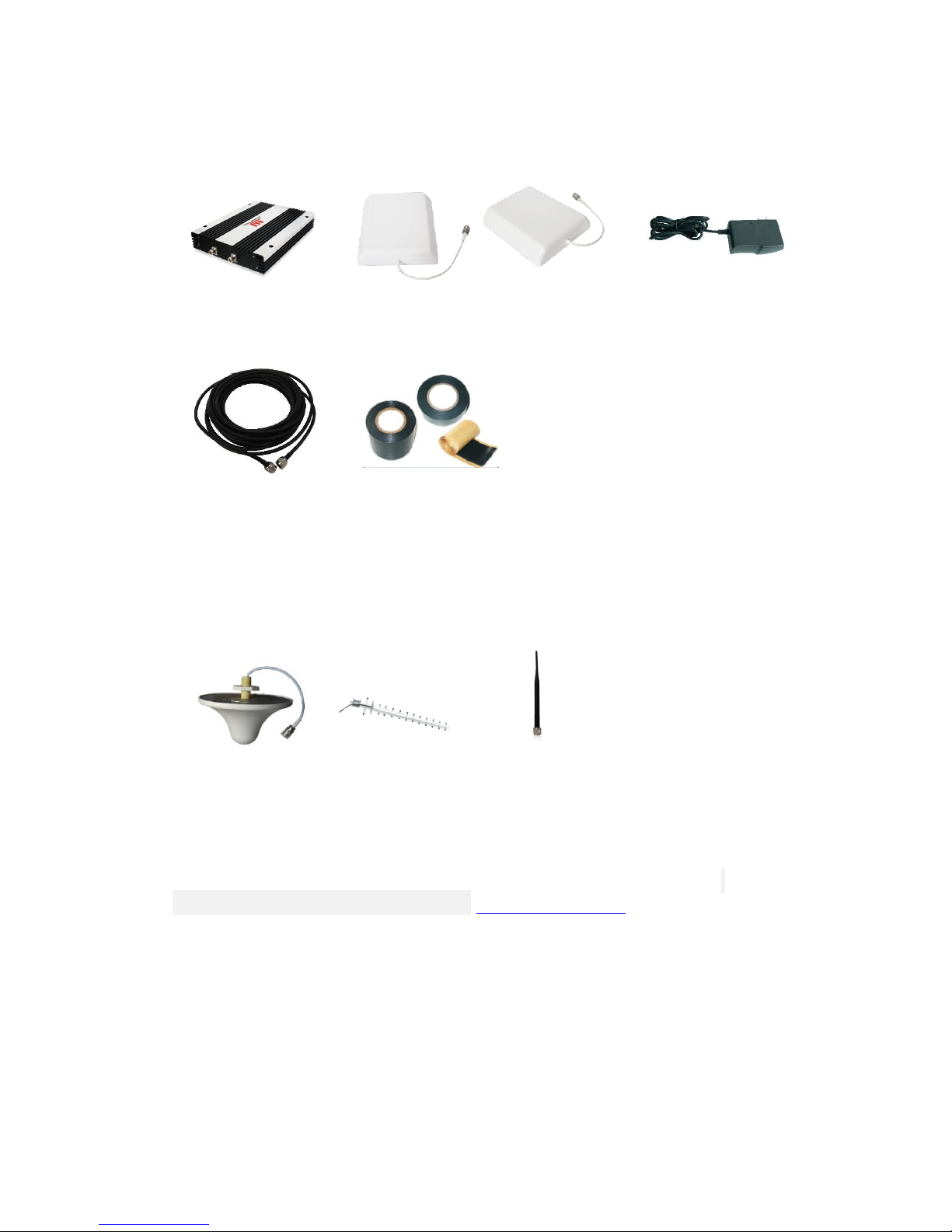
Installation of donor antenna
In mostcases, logarithmic periodic antenna is the best choice.
You can also choose outdoor panel antenna or YAGI antenna
as other options.
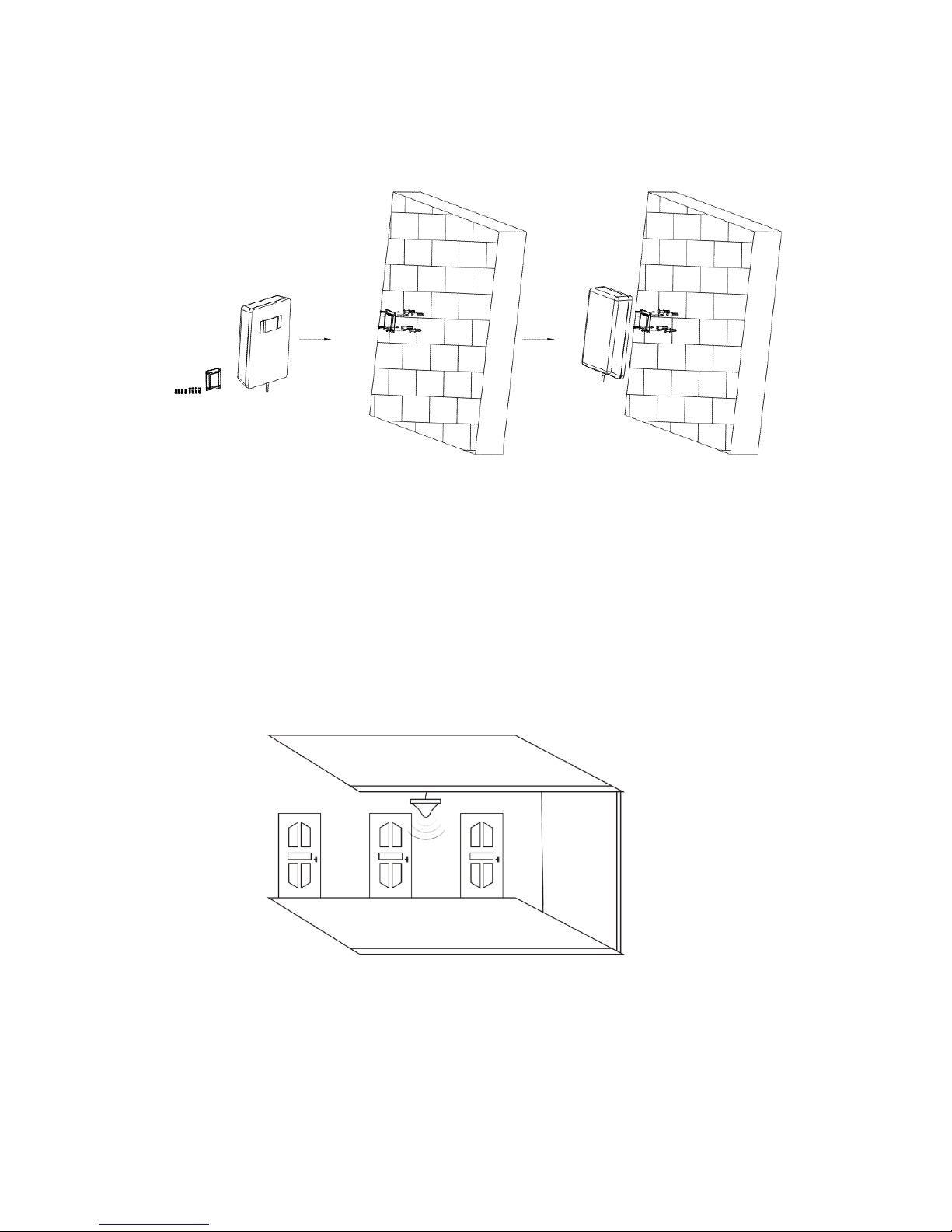
There are 2 types of installation: wall mount or pole mount.
Wall mount installation is recommended for your convenience.
Step1: Unscrew antenna from L-mounting bracket on antenna
base with a wrench.
Step2: Mount vertical plate of the L-bracket on the wall with

7
supplied screws.
Step3: Screw antenna back onto horizontal plate to the wall
with supplied screws.
Notes:
Wrap waterproof tape around the connectors between a donor antenna and feeder lines to avoid
water or other kinds of damage
Install the Indoor Antenna
In most cases, Indoor panel antenna is the best choice. You
can also choose Omni ceiling antenna or whip antenna as
other options.
Step1: Select a place on the wall of the area where you want
better reception.
Normally, to provide an overall coverage, you will need to
choose a corner.
Step2: Drill the screw to the wall and mount bracket on the
wall.

8
Step3: Put the panel antenna on the bracket.
When you choose indoor Omni ceiling antenna or whip antenna,
the bestplace to install it is in the center of your house as the graph
shows.
It is better to use a directional panel antenna or Yagi when the
area is long and narrow (corridors, long row of houses in two sides,
tunnels, elevators or rural open space)

9
Install the signal booster
Step1: Select a location close to a power outlet on a wall.
Step2: Mount the booster with screws included into the kit as
shown in the picture.
Step3: Connect the outdoor antenna cables to the booster
connector marked as “outdoor”. Tighten the connection by
hand or with a wrench.
Step4: Connect the indoor antenna cables to booster
connector marked “indoor”. Tighten the connection by hand or
with a wrench.
Step5: Connect the AC power cord to the signal booster, then
plug in into the electrical outlet.
Step6: Power on the booster.

10
Booster Commissioning
After the booster is on, it will automatically adjust best performance
with the intelligent automatic gain control function. No manual
operation is needed.
if the alarm LED flashes green or orange, that means the
booster is working properly. Check the coverage, if it is
good, the commissioning is finished. If not, you can adjust
outdoor antenna position to get better outdoor signal
strength or move the indoor antenna to better cover the
weak signal area.
If the alarm LED is flashing red, that means self- oscillation
is occurring. To enhance the isolation you can enlarge the
distance between indoor and outdoor antennas or add a
barrier between the antennas. Adjust until the alarm LED
turns green or orange.
Booster installation
Connection from cable to Booster

11
If the alarm is still flashing red, the MGC function can provide
further assistance as shown below.
Booster’s port description
The following image shows the key components of booster. There
are 3 kinds of components. The first one is connectors to the
outdoor and indoor antennas. The second is LEDs for each band.
LEDs indicate power and signal alarm. The third is DIP switch for
MGC function. The following table and graph show the details.
Connecter to outdoor
antenna
Connect to power
Connecter to indoor
antenna
Gain attenuation
DIP switch
LEDs indicate

12
DIP switches
The DIP switches are used to manually adjust
their band gain attenuations.
Switches 1-5 control G/D/W band’s DL attenu
ation, 6-10 control G/D/W band’s UL attenuatio
n.
The booster will work onits MAX gain mode, but in some cases, we don’t need
such a big value. MGC function will help to provide a loss. For example in the
image above, 1 represent 5dB and 2 represent 10dB, if youpress both 1 and 2
button, you can get a loss of 5dB plus 10dB which is15 dB loss.
LEDs
Status and definition of ALARM indicators (only works for downlink
signals):
Status
ALARM
Green
It is working in linearity
Warning: Input signals may be not enough, so
please check oncoverage effect, do not do
anything if it is good; otherwise please check the
donor antenna position.
Orange
It is working in linearity (A little stronger input
signals or slight self oscillation have occurred.)

13
Solution: Please adjustantennas or slowlyadd
the attenuationby MGC till you find the “edge
point” (I.E. the Alarm LED shall stayat green color
slightly turning to orange). Stop immediately when
the LED color changes, it’s enough to provide
best coverage.
Red
There are strong input signals or severe
self-oscillation, measures must be taken. Please,
note that our repeaters have auto shut off
function, so the red color status canonlymaintain
for 5 seconds.
Flashing Red
There are strong input signals or severe self
oscillation to lead that booster breaks down.
Please check the troubleshooting or FAQ to get
solutions.
Off
Repeater breaks down, or severe self-oscillation
leads to auto mute. Please, re-plug the system
and check if alarm LED turns red. Ifit does,
please, take measures to keep alarm LED green;
if it turns off, it means the power breaks down.

14
Troubleshooting
Problem
Resolution
The signal booster is no
power.
Check the booster switch is turned on.
Check the AC outlet is working.
The booster’s power is on
but the phone is not
connected into the
network and still can not
communicate.
Try to fasten the connections between the different
parts of the system.
Change the direction of donor antenna or its installation
position
Use barriers (like buildings) to block signals of other
operators.
Good downlink signal with
poor communication
quality
Check whether there’s interference
Consult the operator whether the signal source base
station works well
Adjust uplink gain to balance uplink and downlink
The power is onbut it has
a signal fluctuationor a
flashsignal.
Firstly, check whether the alarm LED is orange. The
orange light shows the insufficient isolation.
Secondly, adjust the antennas’ direction or position or
enlarge the distance between them.
Thirdly, reduce the booster’s gain by ATT DIP if the
abovementioned methods don’t work.

15
Specifications
RF Parameter
Uplink
Downlink
Frequency Range
GSM900&UMTS
890~915MHz
935~960 MHz
DCS<E
1710~1785MHz
1805~1880MHz
UMTS2100
1920~1980MHz
2110~2170MHz
Max .Gain
F10-GDW
60dB
65dB
F15- GDW
65dB
65dB
F20- GDW
65dB
70dB
Max .Output Power
F10- GDW
10dBm
10dBm
F15- GDW
10dBm
15dBm
F20- GDW
15dBm
20dBm
MGC ( Step Attenuation )
≥31dB / 1dB step, dip switch control
AGC
Adjust automatic, with auto shut off function
V.S.W.R
Typical≤3
Electrical Parameter
Impedance
50 ohm
Power Supply
Input AC90~264V,output DC12V/7A
LED Alarm
Power LED
Power Indicator
ALC LED
Orange @ ALC 1~5 dB, Red @ ALC 15 dB
~20 dB, LED off after 5 seconds red color
Mechanical Parameter
I /O Port
N-Female
Dimensions
9.9*13*2.1inch/250*330*53mm
Weight
≤9.9lbs/4.5KG
Environment Parameter
Operating Temperature
-25ºC~+55ºC
Relative humidity
5% - 95%
Barometric pressure
55 kPa -106 kPa
Environment Conditions
IP40

16
Product Warranty
30-Day Money-Back Guarantee
All Huaptec products are protected by a 30-day money-back
guarantee. If for any reason the performance of any product is not
acceptable,the productmaybe returned to the resellerwith adated
proof of purchase.
2-Year Warranty
Huaptec Signal Boosters and kits are warranted for 2 years.
Customers can choose to return the Signal Boosters and kits directly
to the manufacturer at the purchase expense with a dated proof of
purchase and a Returned Material Authorization (RMA) number
supplied by Huaptec.
Huaptec would provide 2 options, repair or replace of the product.
This warranty does not apply to any Signal Boosters or kits
determined by Huaptec as subjected to misuse, abuse, neglect, or
mishandling that alters or damages physical or electronic
properties. Failure to use a surge protected AC Power Strip with at
least a 1000 Joule rating will void your warranty.
All Huaptec products that are packaged with other Huaptec
accessoryproducts are intended forresale and use as asingle unit.
Such product kits are required to be sold to the end users or
subsequent reseller as they were initially packaged. RMA numbers
may be obtained by contacting Technical Support at
086-0755-29921615

17
Safety Warnings
Users must follow the principles below:
Booster should follow system requirements of communication
equipment, assure good grounding and lightning protection.
The power supply voltage of booster should meet the standards of
security requirement; any operation shall be carried out only after cutting
offpower in advance. Onlythe professional is authorized for the operation.
Do not dismantle machine, maintain or displace accessories by
yourself, in this way, the equipment may be damaged and you may even
get anelectric shock.
Do not open the booster, touch the module of booster, or open the
cover of module to touch the electronic component. The components will
be damaged due to electrostatic.
Please keep away from heating-equipment, because the booster
will dissipate heat during working. And do not cover booster with anything
that influences heat-dissipation.

18
Table of contents
Other Huaptec Extender manuals
Popular Extender manuals by other brands

Rose electronics
Rose electronics CrystalView DVI Multi Quick installation guide

Ihse
Ihse Draco Series Keyboard Commands

Fluke
Fluke GBK-50M instructions

Extron electronics
Extron electronics DTP HDMI 4K D Series user guide

Samsung
Samsung Verizon 4G LTE Network Extender user guide

KVM-TEC
KVM-TEC USBflex Quick installation