Huaptec HiBoost Hi20-3S-Plus User manual

5th FL, E BLDG, Sogood Science Park, Sanwei Community, Hangcheng Street, Xixiang, Bao’an, Shenzhen, China
518102
E-mail: info@Huaptec.com Website: www.huaptec.com
User Manual
HiBoost Booster - Hi20-3S-Plus/ Hi20-5S-Plus/Hi20-6S-Plus, Hi23-3S-Plus/ Hi23-5S-
Plus/Hi23-6S-Plus
Hi Boost Professional Signal Boosters
Manuel de Putilisateur
HiBoost Booster - Hi20-3S-Plus/ Hi20-5S-Plus/Hi20-6S-Plus, Hi23-3S-Plus/ Hi23-5S-
Plus/Hi23-6S-Plus
Amplificateurs de Puissance Professionnels HiBoost
Betriebsanleitung
HiBoost Booster - Hi20-3S-Plus/ Hi20-5S-Plus/Hi20-6S-Plus, Hi23-3S-Plus/ Hi23-5S-
Plus/Hi23-6S-Plus
Professionelle HiBoost Signalverstarker
Manuale d'uso
HiBoost Booster - Hi20-3S-Plus/ Hi20-5S-Plus/Hi20-6S-Plus, Hi23-3S-Plus/ Hi23-5S-
Plus/Hi23-6S-Plus
Amplificatore di Segnale HiBoost Professional
Manual de Usuario
HiBoost Booster - Hi20-3S-Plus/ Hi20-5S-Plus/Hi20-6S-Plus, Hi23-3S-Plus/ Hi23-5S-
Plus/Hi23-6S-Plus
Amplificadores de serial profesionales HiBoost

2/ 19
Table of Content
Preface............................................................................................................................................................. 3
Glossary of Terms ............................................................................................................................................ 3
Safety Warnings............................................................................................................................................... 4
Overview of HiBoost Professional Booster ............................................................................................ 5
Package Contents .................................................................................................................................... 6
Booster Operation Guide................................................................................................................................. 8
System Page ............................................................................................................................................ 8
Warming Message Interface.................................................................................................................... 9
Install HiBoost Booster System .................................................................................................................... 10
Before You Install.................................................................................................................................. 10
Installation Overview............................................................................................................................. 10
Booster System Installation Examples.................................................................................................. 11
More about "Alarm" legend indication ................................................................................................. 15
More about "NET" legend indication.................................................................................................... 15
Troubleshooting............................................................................................................................................. 16
Main Specification ........................................................................................................................................ 18
Product Warranty........................................................................................................................................... 19
Huaptec Contact Way.................................................................................................................................... 19

3/ 19
Preface
This user manual describes design, installation, commissioning and maintenance of Hiboost
professional signal boosters. Please read user manual carefully before installing and
maintaining the boosters.
The information in this manual is subject to change without prior notice. Suggestions are
welcomed about the manual improvement.
Booster Model
The user manual can be used for the models as below: Hi20-3S-Plus/ Hi20-5S-Plus/Hi20-6S-
Plus, Hi23-3S-Plus/ Hi23-5S-Plus/Hi23-6S-Plus.
Note: The users of repeaters should get permission from the mobile providers for the use and
installation of the repeater
Glossary of Terms
Item
Definition
700MHz
Available on NR700(703~733MHz/758~788MHz) network
800MHz
Available on LTE800(832-862MHz/791 -821 MHz) network
900MHz
Available on EGSM900(880~890MHz/925^935MHz) and
PGSM900{890~915MHz/935~960MHz),
WCDMA/UMTS900(880~915MHz/925~960MHz) networks
1800MHz
Available on GSM/LTE1800(1710~ 1785MHz/1805-1880MHz) networks
2100MHz
Available on 3G(WCDMA/UMTS2100)(1920-1980MHz/2110-2170MHz) networks
2600MHz
Available on LTE2600(2500-2570MHz/2620~2690MHz) network
RF
Radio Frequency
ATT
Attenuation
ALC
Automatic
Level Control
AGC
Automatic Gain Control
MGC
Manual Gain Control
LNA
Low Noise Amplifier
PA
Power Amplifier
dB
Decibel
dBm
Decibels relative to 1 mill watt
UL
Uplink

4/ 19
DL
Downlink
Hz
Hertz
MHZ
Megahertz
NF
Noise Figure
RSSI
Received Signal Strength Indicator
Safety Warnings
Users must follow the principles stated below:
The booster should follow system requirements of mobile signal enhancement, assure
good grounding and lightning protection.
Booster's power supply voltage should meet the standards of security requirements;
Any operation should be carried out only after cutting off power in advance. Only the
professional user is authorized for the operation.
Do not dismantle the machine, maintain or displace accessories by yourself. In this way,
the equipment can be damaged and you can even get an electric shock.
Do not open the booster, touch the module of booster, or open the cover of module to
touch the electronic component. The components will be damaged due to electrostatic.
Keep away from heating equipment, because the booster will dissipate heat during
working. And do not cover booster with anything that influences heat-dissipation.
The device has a plug connection, the socket must be close to the device and accessible.
During the transportation and storage process, the device should avoid the humid
environment, prevent violent impact and avoid strong vibration.
Operating Temperature range is -10 - +55 degrees Celsius.
The Body Separation distance is 50cm by using the procedure of MPE calculation.

5/ 19
Overview of HiBoost Professional Booster
USAGE AND INSTALLATION RESTRICTIONS
HiBoost professional boosters are designed to help mobile users to amplify weak cell phone
signal. The devices are bi-directional. The outdoor antenna receives the signal from the cell
tower and transmits it to the signal booster, the booster amplifies the signal and the indoor
antenna sends it to your mobile device. Visa versa, the signal.
Signal booster devices for NR700, LTE800, EGSM/PGSM/WCDMA/UMT900,
GSM/LTE1800, WCDMA/UMTS2100, and LTE2600 mobile network operators, holders of
the corresponding licenses and in each case within the frequencies assigned to them, since
they are broadband amplifiers acts.
The new HiBoost generations are self-regulating and switch themselves off in critical
situations because they are equipped with C.A.S. (automatic shutdown control). If installed
incorrectly, these systems can cause serious disruptions to mobile network operators, with
legal and economic consequences for the owner of the kit and the installer who installed the
antennas.
Huaptec Telecom GmbH assumes no liability for incorrect installation by inexperienced and
unqualified personnel or in any case by personnel without the necessary equipment and
license.
Furthermore, Huaptec Telecom GmbH also assumes no liability for improper use of the field
expansion kits due to incorrect positioning and alignment of the external and internal
antennas, which can cause problems for other users or disruptions to mobile network
operators and providers.

6/ 19
Booster Principle Analysis: Signal transmitted from Base Station and received by the Outdoor
antenna and amplified by the booster, then delivered by the Indoor antenna and finally received by
user’s media device. After that, signal produced by your phone is also received by the indoor antenna,
amplified by the booster, and then sent back to the cell tower through the outdoor antenna.
Package Contents
HiBoost Professional Signal Booster Standard Packing List
No.
Name
Description
Quantity
1
HiBoost Professional Signal Booster
1
2
Adapts
Triple Band 12V/7A
Quintuple Band 12V/7A
Sextuplet Band 12V/7A
1
3
Power Cord
European Standard Plug
4
Plastic expansion bolt
Triple Band ^8
Quintuple Band ^8
Sextuplet Band ^8
5
5
Tapping screw
Triple Band
M6*50
Quintuple Band M6*50
Sextuplet Band M6*50
4
6
Hanging folder
Triple Band mount hardware
1
7
User Manual
Triple/Quint
/Sextuplet Band
1
8
Outdoor Wide Band Directional Antenna
N-Female
1
9
Hiboost 5D low-loss cable
50 feet, N-male
1
HiBoost Professional Signal Booster optional panel pro kit/omni pro kit includes the following
accessories:
No.
Name
Description
Quantity
1
Indoor Wide band panel/omni Antenna
N-Female
1
2
Hiboost 5D low-loss cable
50 feet, N-male
1

7/ 19
Model
Standard Package
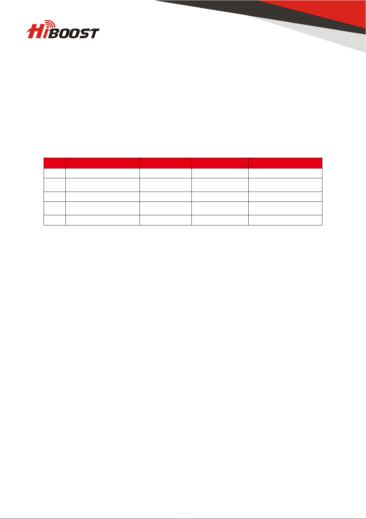
Content Accessories Standard Kit
Hi23
-3S-Plus / Hi20 -3S-Plus
Hi23
-5S-Plus / Hi20-5S-Plus
Hi23
-6S-Plus / Hi20-6S-Plus
Note: The booster requires outdoor and indoor antennas connected with appropriate RF
cables. The length of cable or other accessories needed can vary according to the size and
construction materials used in the building, outdoor signal strength and layout of the structure.
Please contact us for assistance in designing your system.
(If you need to add more indoor antennas or other accessories, please contact Huaptec Support Team
on the phone 044- 20-3239 5802 or by e-mail sales2@huaptec.eu.)
Features
Embedded CPU, self-adaptive intelligent system very easy to use and install, better
performance is guaranteed even under complicated and constantly changing RF
environment conditions.
ISO: Intelligent isolation processing to avoid self-oscillation, quite wide adjusting range
to stabilize the signal strength/quality for clearer voice/ higher data throughput and avoid
interference with mobile networks.
ALC: Intelligent automatic level control, quite wide adjusting range to stabilize the
output power and improve the signal quality for clearer voice and higher data throughput.
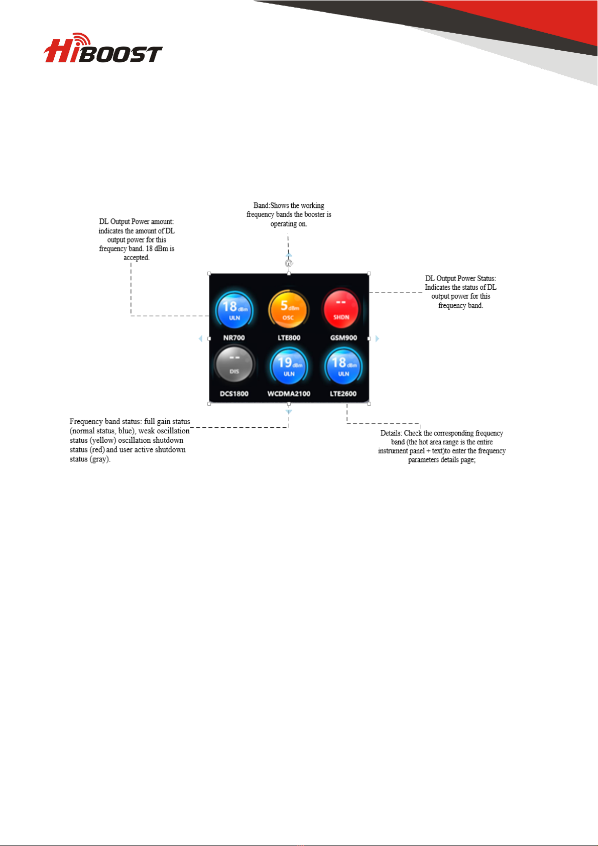
LCD Display: Displays each of Sub-Band status, actual gain, uplink and downlink output
power which makes booster installation and troubleshooting much easier.
MGC: Control buttons to adjust the gain for both uplink and downlink independently,
31dB range.
Excellent RF performance, larger coverage area, clearer voice and higher data
throughput.
Elegant design, compact size, very low power consumption to minimize cost during
operation and low heat dissipation.
Local Monitoring: It's easy to adjust and control booster performance locally via
Bluetooth or a mobile app using Wi-Fi.

8/ 19
Booster Operation Guide
System Page

9/ 19
Warming Message Interface
Repeater system will strictly check Self-oscillation degree for all of sub-band and firstly will
show abnormal status (Orange) in Menu page, ISO and ALC function would auto generate
and if user enter into the soft Self-oscillation sub-band, user could check more details about
Self-oscillation with recommend info.
if not working and Self-oscillation get seriously, which overcome ISO and ALC function
address range (ALC≥42dB, ISO≥42dB), the Sub-band (with Self-oscillation) would be auto-
shutdown ass above message, which shows shutdown status (red) for this Sub-band in Menu
Page, to protect Base Station wouldn’t get interference.
This system auto-generate message caused by excessively strong signals from cell tower,
referring to below troubleshooting sections.

10 / 19
Install HiBoost Booster System
Before You Install
Make sure you have sufficient cable length between the outdoor, indoor antennas and the
booster in case you do not have a standard kit.
Make sure the place where you install the booster is near to one existing electrical outlet.
It should also be well ventilated, away from excessive heat, moisture, and direct sunlight.
Hi20-3S/5S/6S and Hi23-3S/5S/6S installation tools and accessories
Num.
Name
Specification
Quantity
Remark
1
Plastic expansion bolt
^8
5
Standard accessories
2
Tapping screw
M6*50 4
Standard accessories
3
Hanging folder
1
Standard accessories
4
Reciprocating drill
1
Provided by engineer
5
Shot bit
^8 1
Provided by engineer
Installation Overview
Installation is easy to perform in 4 simple steps:
1) Find the strongest received signal for the location of the outdoor antenna.
2) Install the outdoor antenna on the roof to obtain the strongest downlink signal from
the local cellular towers. It should also be as far away as possible from where you
plan to place the indoor antenna (vertical separation is more important than
horizontal separation).
3) Install the indoor antennas where you want to improve the signal level.
4) Mount the booster, connect the cables from the outdoor antenna and indoor antenna
at the designated ports, and connect the booster to the AC supply (make sure all the
cables are connected before applying power).

11 / 19
Booster System Installation Examples
Step 1. Installation of OutdoorAntenna
1.1 How to find the location with the strongest received signal
The booster's main function is to improve a weak RF signal inside a house, office or any other
indoor area. The received outdoor downlink signal strength directly affects the efficiency of
the indoor coverage. That is why it is crucially important to install the antenna at a good
location and point it properly towards a tower where signal reception is the strongest.
There are two methods that can be used to find the strongest downlink signal from the local
towers.
• Mobile Phone Method
You can use a mobile to test signal strength near the window or on the top of the building. The
number of bars on network indicator will define the approximate strength of the received
signal. Normally, the roof of the building is the best place to receive the strongest signal. As
shown in the graph below, you need to test the signal in points from A to E, and select a place
with the best signal strength for outdoor installation. It is recommended to use a mobile app
that can display signal level, since it is more accurate than checking signal bars.

12 / 19
• Signal Supervisor method (for Hi20 Model and Hi23 Model)
Connect your booster with your smartphone through the Signal Supervisor application.
Temporarily fix the outdoor antenna on the roof and check the output power and gain values
on your mobile phone. Turn the antenna slowly until the application shows maximum power.
Once this is achieved, the current location is the best to maximize the performance of your
amplifier.
Attention: for Hi20 models of the Hi20-3S-Plus/ Hi20-5S-Plus/Hi20-6S-Plus Series the
output power is 20dBm, the maximum output gain is 70dB. For Hi23 models of Hi23-3S-
Plus/ Hi23-5S-Plus/Hi23-6S-Plus Series power amplifiers, the output power is 23dbm, the
maximum gain is 75dB.
1.2 Install OutdoorAntenna
Install the outdoor antenna at the location with the strongest received signal.
IMPORTANT: Testing the signal 3 times in the desired location before installing the outdoor
antenna will help ensure the smoothest and stable phone calls and data transmission.
In most cases, outdoor wideband directional antenna is the best choice. You can also choose
an outdoor wide- band panel antenna as an option.
Pole mounting is recommended for your convenience:

13 / 19
Outdoor Wide Band Directional Antenna Installation:
Note: Wrap waterproof tape around the connectors between outdoor antenna and feeder line
to avoid water or other kinds of damage.
Step 2. Install IndoorAntenna
Select indoor panel antenna or Omni-ceiling antenna as an indoor antenna according to your
needs to provide indoor coverage.
Install the indoor panel antenna as shown on the graph below.
If you have an indoor Omni ceiling antenna, the best place to install it is the center of your
house. Install Omni ceiling antenna as shown in the graph below.
NOTE: the required distance between the indoor and outdoor antennas is 10-15 m.
Step 3. Install Signal Booster
Select the location near a power supply on a wall
Mount the booster with the screws included into the kit as shown on the graph below.

14 / 19
Connect the outdoor antenna cable to booster connector marked as "outdoor". Tighten the
connection by hand or with a wrench.
Connect the indoor antenna cables to booster connector marked as "indoor". Tighten the
connection by hand or with a wrench.
Connect AC power cord to the signal booster, then connect the plug to the electrical
outlet to power on the booster. Note: the required booster mounting distance above the
floor is 1-1,8 m.
If it's necessary to install multiple indoor antennas solutions, please contact us. We will
provide you with a professional installation coverage plan.
Step 4. Booster Commissioning
Overview: The booster has an intelligent startup system; booster commissioning is an
automatic process able to guarantee system optimal performance.
As soon as you finish booster system installation, plug it in a power supply to power on the
booster. It will start working and checking the receiving signal strength and the isolation to
ensure best system performance. Automatic adjustment will take about 3-5 seconds.
After the booster starts, check if the coverage is improved as you wish. The booster
commissioning is completed.
In case the coverage is not enough, please check the following conditions.
1. The rated output power is reached, but the coverage is not enough or the signal in some
areas are not improved:
Check whether the indoor antenna is installed correctly or not, try to change the
antenna position to improve coverage.
Check if it is necessary to adjust the direction of the indoor antenna.
Check whether it is necessary to add more indoor antennas since barriers block the
signal.
2. The rated output power is not reached.
Change the position or direction of the outdoor antenna to get a stronger receiving
signal and higher output power. (Not necessarily to reach rated value as long as the
coverage is enough).

15 / 19
More about "Alarm" legend indication
Alarm Status: indicates if the booster has enough isolation between outdoor and indoor
antennas in order to avoid loop back or so-called self-oscillation. HiBoost is an ideal
mechanism. Smart AGC, to avoid interference with operator mobile networks. "Alarm" long-
team up on LCD display means not only device is powering on, but also ISO function is
working great and self-oscillation has been eliminated.
LED
Status
Meaning
Solution
Alarm
LED
Green
No loop back or no self
-
oscillation
NO action is needed.
Slow Flashing
Green
(Per 2.5S
off, 0.5S on)
Slight loop back or self
—
oscillation
(1dB≤ISO
Attenuation≤
14
dB)
NO action is needed.
Quick Flashing
Green
(Per 0.5S
off, 0.5S on)
Deep loop back or self
—
oscillation
(15dB≤ISO
Attenuation
<42dB)
Not working properly.
Check if
there would be self-
oscillation message and Sub
-band
interface
. Please check the
Troubleshooting section to get a
solution if coverage is not good.
Red
The booster sub-band auto shuts
off for protection due to
severe
loop back or self
-oscillation
(ALC≥42dB,ISO≥42dB)
Not working properly. Please
check the Troubleshooting section
to get a solution.
OFF
The booster
not power up
More about "NET" legend indication
NET indicates the connection establishment between booster and Bluetooth/Wi-Fi, if the connection
established well, NET LED will show Green UP status, otherwise light would be blinking or off.
LCD
Status
Meaning
Solution Methods
NET
status
Green Light up
Mobile is
connected to booster
through Bluetooth/Wi
-Fi
Working properly.
Light off
Mobile
is not connected to booster
through Bluetooth/Wi
-Fi
Not working properly, please
contact with Huaptec EU for
assistance.

16 / 19
Troubleshooting
Problem
Solution
The signal booster has no power.
Check that the AC outlet is working.
The
booster's power is on but the phone is not
connected to the network and still cannot
communicate with the signal.
Try to fasten the connections between the different
parts of the system.
Change the direction of the donor antenna or its
installation positio
n.
Good downlink signal with poor communication
quality.
Check whether there's interference.
Consult the operator whether the signal source base
station works well.
The power is on but the coverage is not good.
Check Alarm LED indications. Take the actions
mentioned below.
Eliminate Alarm LED Quick Flashing and RED problems:
▲Adjust the outdoor antenna direction, keeping it away from the indoor antenna. Restart
booster.
▲Increase the vertical or horizontal distance between the outdoor antenna and indoor
antenna. Restart booster.
▲Use barriers such as walls to increase the isolation.
▲Change the indoor antenna type to an antenna with a more directional antenna pattern.
Orient the indoor antenna and outdoor antenna so they point in opposite directions.
▲Reduce the booster's downlink gain using the manual gain controls. Keep the uplink gain
value and downlink gain value the same, then restart the booster.
Note: Uplink gain must be equal to or not less than 5dB below the downlink gain, to avoid
interference with the local carrier's cell site network.
Target: This situation refers to ISO issue and if issue resolved, the Alarm LED would show
Green light UP status.
Eliminate poor coverage problems when gain or output power value abnormal in Sub-
Band Interface:
• If the signal has not been improved, please check below:
• The weak downlink signal leads to the low output signal level. Change the direction or
position of the outdoor antenna. You may also try replacing the outdoor antenna with a higher
gain antenna to increase the incoming signal.
• Check to see if it is necessary to add more indoor antennas. Barriers such as walls can
block the signal indoors. You should also check the booster to make sure the power is
maximized. Try installing more indoor antennas or replace the booster with a higher powered
one.

17 / 19
• If the signal in a small section of the building hasn't been improved, try the following:
• Check to see if the indoor antenna is installed correctly. Try moving the antenna to
improve coverage.
• Try adjusting the direction the indoor antenna is pointing.
Remark:
• When increasing the downlink gain, make sure the isolation is adequate to prevent system
oscillation
Note: The Alarm LED long-term Green up and the problems of self-oscillation and strong
downlink signals are fixed. In most cases, there is no need to take any additional measures
except for deep self-oscillation or excessively strong signals from the tower. The self-adaptive
ALC and isolation gain processing system automatically solve most problems.

18 / 19
Main Specification
RF Parameter
UL
DL
Frequency Range
700 MHz
703
-733 MHz
758
-788 MHZ
800 MHz
832
-862 MHz
791
-821 MHZ
900 MHz
880
-915 MHz
925
-960 MHZ
1800 MHz
1710
-1785 MHz
1805
-1880 MHZ
2100 MHz
1920
-1980 MHz
2110
-2170 MHZ
2600 MHZ
2500
-2570 MHZ
2620
-2690 MHZ
Max. Gain
Hi20
Model
Hi23
Model
60
dB
70
dB
65
dB
75 dB
Max. output power
Hi20 Model
Hi23
Model
17dBm
20
dBm
20 dBm
23 dBm
MGC (Step Attenuation)
>31 dB/1 dB step
Intelligent AGC*
ALC
ISO
>42 dB
>42 dB
Electrical Parameter
Power Supply
Triple/
Quint/Sextuplet Band
Input AC 100
-
240 V, 50/60 Hz, Output DC 12 V /
7 A
Power Consumption
Triple/
Quint/Sextuplet Band
<4
0W
Input
& Output Impedance 50 ohm
Mechanical Parameter
1
/O Port Type N-Female
Dimensions
Triple/
Quint/Sextuplet Band
220*310*53
mm
Weights
Triple/
Quint/Sextuplet Band
<4.5
kg
Environment Parameter
Operating Temperature
-
10ºC~+55ºC
Relative Humidity
5%
-95%
Barometric Pressure
55 kPa -106 kPa
Environment Conditions
IP
40

19 / 19
Product Warranty
30-Day Money-Back Guarantee
All Hi boost products are protected by 30-day money-back guarantee. If for any reason the
performance of the received product is not acceptable,the client can return the product
within 30-day period and get spent money back.
2-Year Warranty
HiBoost signal boosters are covered with2-year warranty. Huaptec offers two options for the
products under warranty: repair or replace.
This warranty does not apply to Hi Boost signal boosters or kits that have been subjected to
misuse, abuse, neglect or mishandling and that have its physical or electronic properties
altered or damaged. Failure to use surge protectedAC power strip with at least a 1000 Joule
rating will void your warranty.
All HiBoost products that are packaged with Hi boost accessory products are intended for use
and resale as a single unit, and such product kits are required to be sold to the end users or
subsequent reseller as packaged.
For any questions or suggestions do not hesitate to contact Huaptec Support Team on the
phone 044- 20-3239 5802 or by e-mail sales2@huaptec.eu.
Huaptec Contact Way
HuaptecCN
Huaptec EU
Huaptec US
Phone/Fax:086
-0755-29921615
Phone/Fax:
+44 (20) 3239 5802;
+44 (20) 8144
7969
Phone/Fax:(972) 870
-5666
Address:
5th FL, E BLDG, Sogood Science
Park, Hangkong Road, Xixiang,
Bao'an,
Shenzhen, China 518102
Address:
Herderstr.
94, 40721 Hilden,
Germany
Address:
6210 N. Belt Line Rd.
,Ste. 110,
Irving,
TX, 75063
E
-mail :tech@huaptec.com
E
-mail:sales1@huaptec.eu
E
-mail:info@hiboostusa.com
Website
:www.huaptec.com
Website: www.hiboost.com/eu
Website:
www.hiboost.com
This manual suits for next models
5
Table of contents
Other Huaptec Extender manuals