Huawei FusionCol8000-C210 User manual

HUAWEI TECHNOLOGIES CO., LTD.
FusionCol8000-C210 In-room Chilled
Water Smart Cooling Product
Quick Guide
Issue: 04
Part Number: 31500ECR
Date: 2022-06-30

1
1Product Overview
Materials
Delivered with
the Equipment
Cord end terminal (10 mm2) for the indoor unit power cable, OT ground
terminal (10 mm2) for the indoor unit power cable, cable tie, hexagon bolt
assembly (M12x45), and four M6x16 bolts
Engineering
Purchasing
Drainpipe G 1/2 inch outer screw thread
Water inlet/outlet pipe DN50 seamless steel pipe with a G 2 inch external
threaded connector
Water inlet pipe for the
wet film humidifier G 1/2 inch outer screw thread
Cables Active power cable (4 x 10 mm2), standby power
cable (4 x 10 mm2), teamwork networking and
monitoring cables, and equipotential cable (6 mm2
outdoor copper cable)
Others Hoop iron, pipe support, thermal insulation foam,
dedicated glue for thermal insulation foam, and
thread sealant
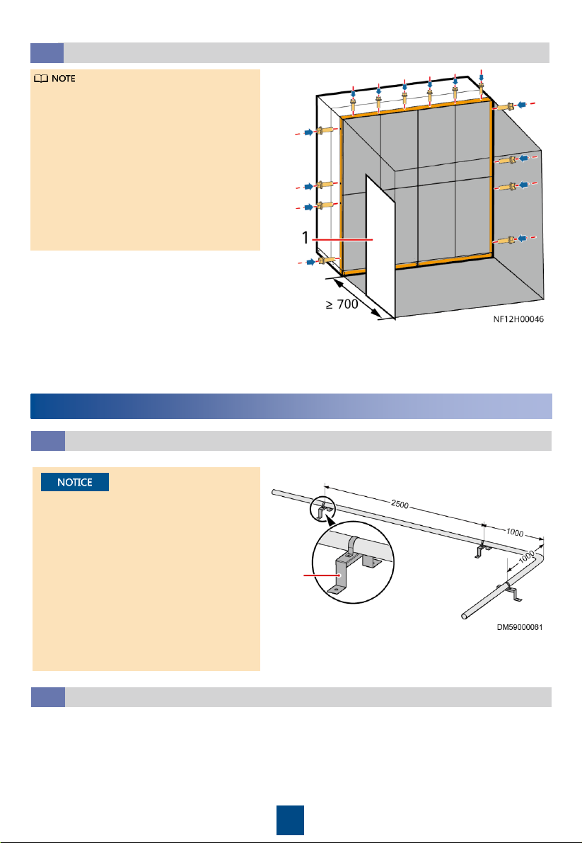
2Engineering Materials
Product Model Pipe Routing Cable Routing Dimensions Without Packing (H
x W x D) (mm)
FusionCol8000-C210 Routed from top Routed from top 2450 x 2350 x 1100
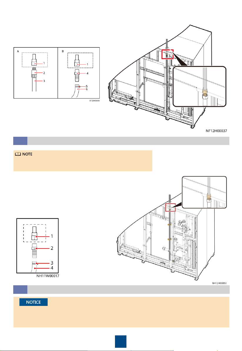
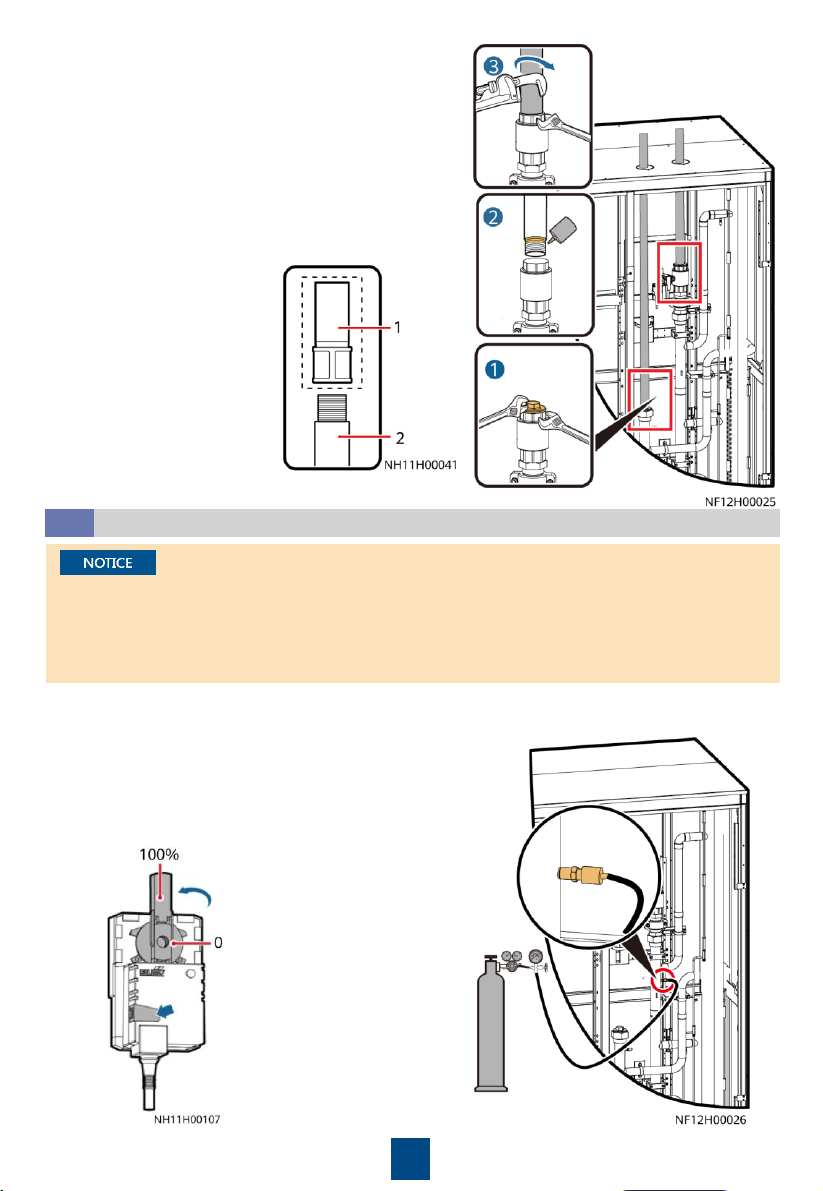
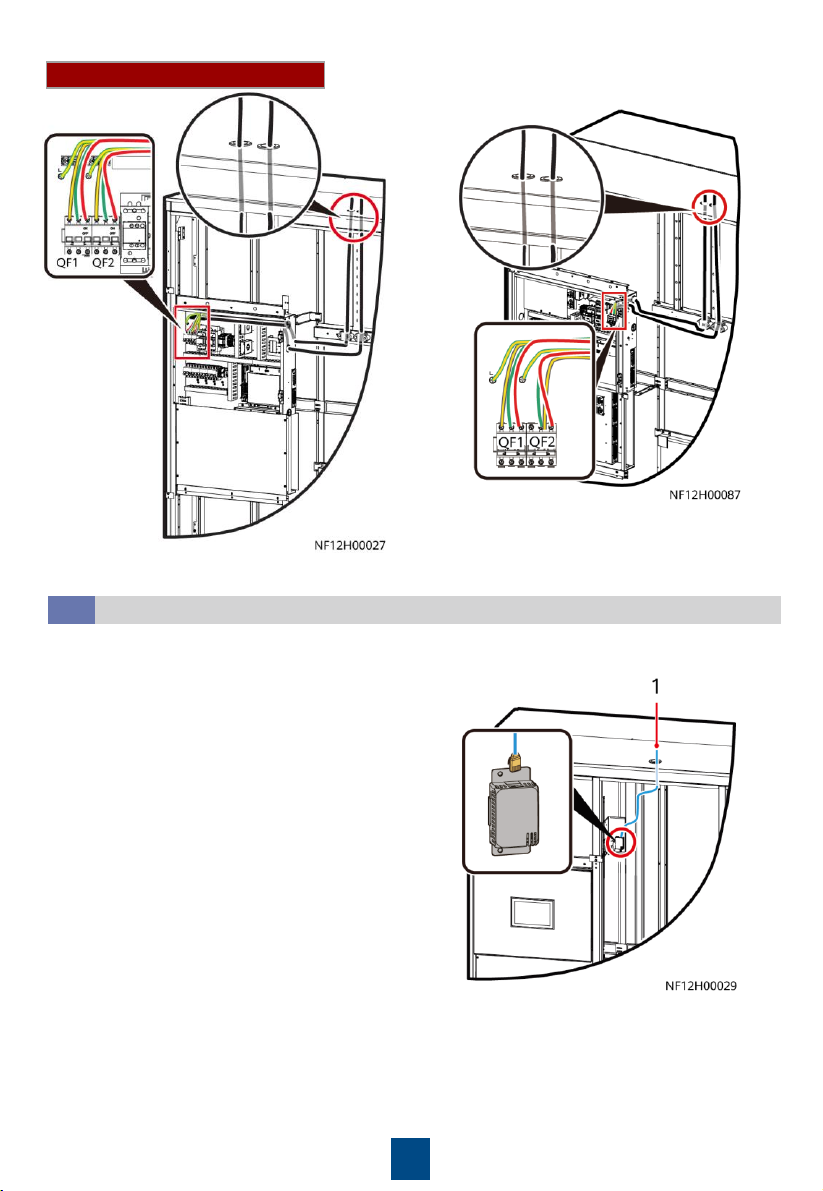
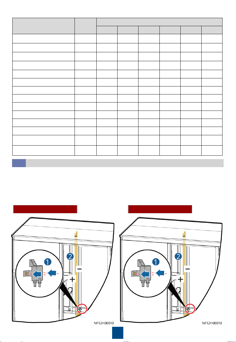
3Installing the Equipment
1. Read the related user manual or instructions before installing the FusionCol8000-C.
2. The unit in this document is a fully configured FusionCol8000-C. If some components are not
configured, skip the corresponding steps.
3. You are recommended to use tools that are fully insulated when installing devices.
4. Only engineers from the manufacturer or engineers certified by the agent are allowed to
install, commission, and maintain smart cooling products. Otherwise, personal injuries and
device damage may be caused, which is beyond the warranty range.
Copyright © Huawei Technologies Co., Ltd. 2022.
All rights reserved.

2
Checking the Nitrogen Pressure and Exhausting Nitrogen
3.2
•The equipment is charged with nitrogen
before delivery. Rotate the exhaust valve
counterclockwise. If there is a hiss sound,
the system is well sealed, and you need to
open the exhaust valve to exhaust the
nitrogen. If there is no hiss sound, contact
Huawei technical support.
•You can open or close the exhaust valve
using a flat-head screwdriver.
Slowly open the exhaust valve to release
nitrogen. After the nitrogen is exhausted, close
the exhaust valve.
Removing Air Filters
3.1

3
Secured on the Floor
•Before securing the equipment, remove the
protective sheet metal from the water pump
exterior.
•The reserved holes in the middle can be selected
for securing based on site requirements.
•Obtain the anchor baffle plate according to the
packing list.
1. Secure the equipment to the floor
using four M12 expansion bolts.
2. Install anchor baffle plates at the
bottom.
Secured with Supports
•Obtain the connecting kits
and screws according to the
packing list.
•A distance of at least 15 mm
must be reserved between
combined cabinets.
Securing the Equipment
3.4
(Display side)
(Display side) 1. Secure the equipment to the base using four
M12x45 bolt assemblies.
2. Install anchor baffle plates at the bottom.
Dimensions of mounting holes on the
floor (unit: mm)
Dimensions of mounting holes on
the base (unit: mm)
Combining Cabinets
3.3

4
(Optional) Connecting the Air Duct
3.5
•An air duct needs to be prepared
onsite based on site requirements.
•When fixing the equipment to the
floor, place the bottom of the air
duct on the floor and use anchor
baffle plates to secure the air duct.
•If the equipment is to be secured to
the base, it is recommended that
you install baffle plates on the base
before securing the bottom of the
air duct.
•Remove the eight screws from
both sides of the equipment.
•Use M4x12 screws to secure the
air duct to the top of the
equipment, and use M6x25
screws to secure the both sides of
the air duct to the both sides of
the equipment.
Pipe
support
1. A 1:100 tilt should be reserved for the
drainpipe and humidifier water inlet pipe.
2. Keep a clearance of at least 25 mm between
pipes. Secure the pipes to supports every a
certain distance.
3. Clean the water inlet engineering pipes to
avoid impurities entering into the humidifier.
4. A reducing valve must be installed if the inlet
water pressure exceeds 0.7 MPa.
5. Pipes should be wrapped with thermal
insulation foam along the route.
Unit: mm
Connecting the Drainpipe
4.2
Both hoses and rigid pipes can be connected. This section uses rigid pipe
connection as an example.
4Installing Pipes
Pipe Layout
4.1
(1) Maintenance door

5
(1) Reserved connector (4) Pagoda connector
(2) Rigid pipe connector (5) Hose clamp (standard)
(3) Rigid pipe (6) Hose
Connection method
Connecting the Humidifier Water Inlet Hose
4.3
A humidifier water inlet hose is delivered with the
equipment and is wrapped around and bound to the pipe.
1. Remove the binding strap from the humidifier water
inlet hose.
2. Pull the hose along the reserved pipe clamp on the
cabinet side to the top of the cabinet and route the
hose through the humidifier water inlet hose hole.
3. Connect the water inlet hose of the smart cooling
product to the engineering pipe.
Connecting the Chilled Water Inlet and Outlet Pipes
4.4
1. Wrap thermal insulation foam around the whole pipes after pipes are connected.
2. Due to the hardening property of yellow adhesive, nitrogen injection and pressure preserve
should be operated 8 hours after the adapter is connected.
(1) Reserved
connector
(2) Pagoda
connector
(3) Hose clamp (4) Hose

6
1. Remove the baffle plate at the bottom of the
cabinet.
2. To avoid deforming the pipe, use a 70# open-end
wrench to fix the pipe nut, use a 36# open-end
wrench to fix the plug, and then remove the plug.
3. Apply thread sealant evenly on the joints of
external screw threads, and install the pipes from
inside out.
4. Use a 70# open-end wrench and an 18# pipe
wrench to fix the pipes.
(1) G 2 inch port with
inner threads (reserved
device port)
(2) Seamless steel pipe
with a G 2 inch external
threaded connector
(Optional) Leakage Test with Nitrogen
4.5
1. Rotate the chilled water valve to the maximum openness (100%).
2. Check that the needle valves and exhaust valves on the pipeline are closed.
•If the pressure decreases, apply soapy water on the pipes, especially pipe joints to check for
any leakage.
•If the pressure is stable, wrap all pipes and connectors with thermal insulation foam.
•Install a reducing valve at the outlet of the nitrogen cylinder. The outlet pressure of the
reducing valve must be not more than 0.8 MPa.
3. Connect the reducing valve and nitrogen cylinder to the
following needle valve, inject 0.8 MPa (when the pressure
is stable) nitrogen, and leave them for 24 hours.
4. Then, check that the pressure reading on the pressure
gauge remains unchanged.

7
Injecting Water to Expel Gas
4.6
•To avoid blockage of the heat exchanger in the smart cooling product due to foreign
matter from the main pipe during the construction, you are advised to clean the main pipe
before water is supplied to the smart cooling product. Turn off the isolation valves on the
water inlet and outlet pipes before the cleaning and turn them on afterwards.
•Open the exhaust valve of each heat exchanger to exhaust nitrogen onsite.
1. Open the general water supply valve.
2. Verify that the chilled water valve is open (100%). If not, press the button on the side of the
actuator, and manually rotate the valve handle to the maximum.
3. Slowly open the exhaust valve to discharge gas.
4. Adjust the gas exhausting speed until no gas flows out of the valve. Then close the exhaust valve.
5. Manually close the chilled water valve.
Leakage Test with Water
4.7
1. Manually open the chilled water valve.
2. Raise the water pressure in the chilled water pipe to 0.8 MPa. If no leakage occurs after 30
minutes, retain the pressure for 24 hours. The expected result is that the pressure drop is less
than 0.01 MPa and the pipe does not leak.
3. Release the pressure in the pipes, and manually close the chilled water valve.
Connecting the Power Cable and Equipotential Bonding Cable
5.1
5Connecting Cables
•Route and bind the cables along the beams and columns of the unit.
•The cabinet has no input neutral wire. You can cut the blue neutral wire and wrap it using
insulation tape.
Connecting the Equipotential Bonding Cable
In the example, the cable is routed from the
top of the cabinet. The underfloor ground
cable is routed through the cabinet bottom.
If a leakage test with nitrogen has been performed, you do not need to perform a leakage test
with water.

8
Connecting the Power Cable
(Optional) Connecting the T/H Sensor Outside the Cabinet
5.2
(1) T/H sensors outside the cabinet
1. Connect the T/H sensor outside the cabinet.
2. Set the DIP switch on the T/H sensor.
(Model without heating)
(Model with heating)

9
Name Address DIP Switch ID
1 2 3 4 5 6
Air return temp/humid 1 1 ON OFF OFF OFF OFF OFF
Air return temp/humid 2 2 OFF ON OFF OFF OFF OFF
Air return temp/humid 3 3 ON ON OFF OFF OFF OFF
Air return temp/humid 4 4 OFF OFF ON OFF OFF OFF
Cold aisle temp/humid 1 11 ON ON OFF ON OFF OFF
Cold aisle temp/humid 2 12 OFF OFF ON ON OFF OFF
Cold aisle temp/humid 3 13 ON OFF ON ON OFF OFF
Cold aisle 4 temp/humid 4 14 OFF ON ON ON OFF OFF
Cold aisle 5 temp/humid 5 15 ON ON ON ON OFF OFF
Hot aisle temp/humid 1 21 ON OFF ON OFF ON OFF
Hot aisle temp/humid 2 22 OFF ON ON OFF ON OFF
Hot aisle temp/humid 3 23 ON ON ON OFF ON OFF
Hot aisle temp/humid 4 24 OFF OFF OFF ON ON OFF
Hot aisle temp/humid 5 25 ON OFF OFF ON ON OFF
Installing a Micro Differential Pressure Sensor
5.3
Connect a pressure inlet tube to the + mark and route it to the positive pressure area of the
equipment room through the hole atop. Ensure that the pressure inlet faces downwards.
Connect a pressure inlet tube to the –mark and route it to the cabinet top through the hole
atop (at the air return side).
Connect the cable terminals of the micro differential pressure sensor to the 4, 5, and 6 terminals
of X502.
Model without heating Model with heating

10
(Optional) Installing a Water Sensor
5.4
The following figure uses the water sensor as an example. A water detection cable can also be
connected.
Model without heating Model with heating
Connecting the Teamwork Network Cable and Monitoring Cable
5.5

11
No.
Name
Description
1
Running indicator
-
2
Alarm indicator
-
3
FE_1 port
MAC_CAN teamwork
4
CAN_IN port
CAN teamwork and RS485 monitoring cascading
5
RS485/12V port
Connects a T/H
sensor.
6
USB port
Connects a
WiFi module or USB flash drive.
7
SW button
Button for restoring factory settings
8
FE_2 port
MAC_CAN teamwork
9
CAN_OUT port
CAN teamwork and RS485 monitoring cascading
10
COM/FE port
Connects a monitoring communications cable.
11
DP port
Connects to the display.
1. Crimp a network cable.
PIN
Color
COM/FE Port (
RS485 Monitoring)
4
Blue
RS485+
5
White
-and-blue
RS485
–
PIN
Color
FE_1 and
FE_2
CAN_IN and
CAN_OUT
RS485/12V
Port
COM/FE Port
(FE
Monitoring)
1
White
-and
-
orange
FE TX+
RS485 T+ (+)
RS485 HT+
FE TX+
2
Orange
FE TX–
RS485 T
–(–)
RS485 HT
–
FE TX
–
3
White
-and
-
green
FE RX+
-
12V
FE RX+
4
Blue
-
RS485 R+
RS485 HT+
RS485+
5
White
-and
-
blue
-
RS485 R
–
RS485 HT
–
RS485
–
6
Green
FE RX–
-
-
FE RX
–
7
White
-and
-
brown
-
CANH
-
-
8
Brown
-
CANL
GND
-

12
CAN teamwork + RS485 monitoring
2. Connect teamwork and monitoring communications cables.
Networking
Teamwork
Monitoring
Protocol
CAN
Modbus
-RTU
Connect the COM/FE port on the main control module of the last smart cooling product in each
group to the RS485 port on the host.
CAN teamwork + FE monitoring
Networking
Teamwork
Monitoring
Protocol
CAN
Modbus
-TCP/SNMP
Customers can purchase Huawei's switch and NetEco for the monitoring system.

13
MAC_CAN teamwork + RS485 monitoring
Networking
Teamwork
Monitoring
Protocol
MAC_CAN
Modbus
-RTU
Connect the COM/FE port on the main control module of the last smart cooling product in each
group to the RS485 port on the host.
MAC_CAN teamwork + FE monitoring
Networking
Teamwork
Monitoring
Protocol
MCA_CAN
Modbus
-TCP/SNMP
Customers can purchase Huawei's switch and NetEco for the monitoring system.

14
(Optional) Connecting the Motorized Damper
5.6
For details about how to connect the motorized damper, see the documents delivered with it.
Check Item Expected Result Actual Result
Cabinet
The cabinet is installed properly without any tilt. The cabinet is
secured to the base by using bolts. The foreign matter inside
the cabinet, such as cable ties and stubs, has been cleaned up.
□Passed □Failed
Fan The fan has no foreign matter inside. □Passed □Failed
Water pan The foreign matter inside the water pan is cleaned up. □Passed □Failed
Differential
pressure
switch
The cable ties are securely tightened around pressure tubes.
There is no foreign matter in pressure tubes. The pressure
tubes show no obvious bends.
□Passed □Failed
Exhaust
valve The exhaust valve is closed. □Passed □Failed
Drainage
valve The drainage valve is closed. □Passed □Failed
Air filter The air filter is correctly installed according to the airflow
direction marked on the frame. □Passed □Failed
Chilled water
valve
The chilled water valve and its actuator are securely installed.
The chilled water connector joints have been wrapped with
thermal insulation foam, and no metal or hose are exposed.
Cables are securely connected to the chilled water valve and
its actuator. Cables to the chilled water valve and its actuator
are secured. Check that the manual button on the actuator is
reset (the button bounces up).
□Passed □Failed
6Installation Verification
7Equipment Power-On
1. Users are classified into admin and operator users, and admin users have more rights than
operator users. The preset password is 000001 for both types of users. For system security
purposes, change the preset password upon first login.
2. A login session automatically expires if no operation is performed in 3 minutes. It is
recommended that you tap at the lower right corner to manually log out after
operations are complete.
Power-On
7.1
1. Turn on the general switch and fan switches QF3, QF4, QF5, QF6. For a device that has two
power inputs, turn on the active power switch QF1 and standby power switch QF2.
2. Powered on the equipment.
•Select the language: English or Chinese.
•Select the date & time settings: date format, date, time, and time zone.
•On the home screen, tap Settings > System Settings > T/H Sensor to change temperature and
humidity control types or set points.

15
(Optional) Teamwork Settings
7.2
The table uses 8 smart cooling products in a teamwork group as an example.
No.
Item
Teamwork Group
No. System Address Teamwork CAN
Resistor Enable
Teamwork
Function Network
Total
Number of
Systems in
This Group
Number
of Running
Systems in This
Group
Rotation
Function
Requirement
Control
11 1 Yes Enable CAN network 8 6 (2 standby) Enable Enable
21 2 No Enable CAN network / / / /
... ... ... ... ... CAN network ... ... ... ...
81 8 Yes Enable CAN network / / / /
All teamwork control parameters can be set on the master smart cooling product. Only
Teamwork group No., System address, Enable teamwork CAN resistor, Teamwork function, and
Networking mode can be set on slave smart cooling products. Other parameters of the slave
units will be modified by the master unit synchronously.
1. Teamwork group No.: A maximum of 32 smart cooling products can be connected in a
teamwork group and a maximum of four teamwork control groups can be connected in an
RS485 network. To increase the network management system (NMS) response speed, it is
recommended that one monitoring system should connect to one teamwork control group.
2. System address: In a teamwork control group, each smart cooling product address must be
unique, and the address of one smart cooling product must be 1 (master smart cooling
product).
3. Teamwork CAN resistor enable: After connecting smart cooling products 1 to 32 (determined
by cable routing sequence) in series, set the parameter to Yes for the first and last smart
cooling products in the teamwork control group, and retain default values (No) for other
smart cooling products.
4. Teamwork function: Indicates whether to disable or enable the teamwork function. If disabled,
a unit operates independently. If enabled, a unit operates in team with other units.
5. Network: The networking mode set on the screen must be consistent with the actual
networking mode. Otherwise, the teamwork control function will be unavailable.
6. Total number of systems in this group: Indicates the number of precision smart cooling
products in a group. The value is an integer ranging from 1 to 32.
7. Number of running systems in this group: Specifies the number of running FusionCol8000-Cs
in a group. The value ranges from 1 to the number of FusionCol8000-Cs in the group.
8. Rotation function: Enable the active and standby smart cooling products to work alternately.
This function is recommended when the heat load is even. When Rotation is Enable, the
parameters for the rotation period and rotation time and forced rotation can be set based on
the customer's requirements.
9. When Requirement control is set to Enable, the master smart cooling product synchronizes
operating data (parameters such as the T/H control type, temperature set point, and
humidity set point for the master smart cooling product) to the slave smart cooling product,
and all the precision smart cooling products in the group refer to the mode delivered by the
master smart cooling product. When Requirement control is set to Disable, the master smart
cooling product does not synchronize operating data to the slave smart cooling product, and
all the smart cooling products operate based on their own requirements, not referring to the
mode delivered by the master smart cooling product.

16
a. On the home screen, choose Settings > Comm Settings > Modbus Settings. The value
should be consistent with that set on the NMS.
b. Set the communication address. The communication addresses of two smart cooling
products connecting to the same NMS must be unique.
c. Set RS485 monitoring grouping to Enable for the smart cooling product connected to
the host through the COM/FE port, and set this parameter to Disable for other smart
cooling products.
a. On the home screen, choose Settings > Comm Settings > WAN IP Settings. Set IP address,
Subnet mask, Gateway according to the actual plan.
b. On the home screen, choose Settings > Comm Settings > Modbus Settings. The Link mode
can be set to Server and Client, Client, or Server. Set this parameter based on the site
requirements.
c. If Link mode contains Client, set Client encryption to Enable. Enter the actual IP address of
the NMS. When Client encryption is set to Enable, set NMS port number to 32907.
RS485 Monitoring Network Cable (Modbus-RTU Protocol)
FE Monitoring Network Cable (Modbus-TCP)
(Optional) Setting Communications Parameters
7.3
8Commissioning
•To prevent the effect of misoperation on the system, log in as the operator user first before
modifying parameters. Confirm with Huawei before modifying parameters which cannot be
modified by the operator user; otherwise, Huawei will not be liable for any consequences of
the modification.
•The following figure shows the flowchart for the first power-on. If the system has been
powered on previously, choose Maint > Wizard Startup to perform the commissioning.
•The indoor fan is a mandatory commissioning item. Other components can be commissioned
depending on actual requirements.
•The Service Expert app can be downloaded from Huawei App Store. The app is supported by
only Android at present.
•The Service Expert app supports both online boot and offline boot. The offline boot is taken
as an example in the following part. For details about online boot, refer to the section about
startup in
FusionCol8000-C210 In-room Chilled Water Smart Cooling Product User Manual
.
•Open the Service Expert app, choose Startup Commissioning > Offline Boot, and enter the
bar code on the system LCD and the verification code. The app automatically generates a
startup password.
•The encryption mode must be the same as it on the NMS.
•After the encryption operation CBC is set, the system automatically restarts. Therefore,
exercise caution when performing this operation.
•For details about SNMP settings, see the user manual.

17
9Checking After Commissioning
Check Item Result
The controller has exited from the diagnostic mode. □Passed □Failed
The temperature and humidity are correctly set. □Passed □Failed
10 Power-Off
1. Tap Shutdown on the LCD home screen.
2. Turn off all switches on the smart cooling product.
3. If the smart cooling product will not be used over a long
time, drain the water in the heat exchanger or take
antifreeze measures to avoid frost cracks.
The password protection
function during startup and
shutdown has been added.
Perform operations as required.
Appendix 1: Precautions Against Adding Glycol
For details about adding glycol, refer to the
FusionCol8000-C210 In-room Chilled Water Smart
Cooling Product User Manual
.
To prevent glycol solution from corroding pipes and the heat exchanging coil, corrosion inhibitor
should be mixed into the glycol solution. For details about the mixing schemes, consult glycol
experts.

Huawei Technologies Co., Ltd.
Huawei Industrial Base, Bantian, Longgang
Shenzhen 518129 People's Republic of China
www.huawei.com
Other manuals for FusionCol8000-C210
3
Table of contents
Other Huawei Chiller manuals
Popular Chiller manuals by other brands

Gree
Gree LSQWRF35VM/NhA-M Service manual

Hitachi
Hitachi RCUE40AG2 Service manual

Telemark
Telemark TVP-2000 Operation, installation and service manual

Hoshizaki
Hoshizaki Lancer Glycoolpac 27hx Installation, operation & service manual

Polar Refrigeration
Polar Refrigeration CB507 instruction manual

Econlux
Econlux Jellyflap instruction manual