manuals.online logo
Brands
  1. Home
  2. •
  3. Brands
  4. •
  5. Huawei
  6. •
  7. Firewall
  8. •
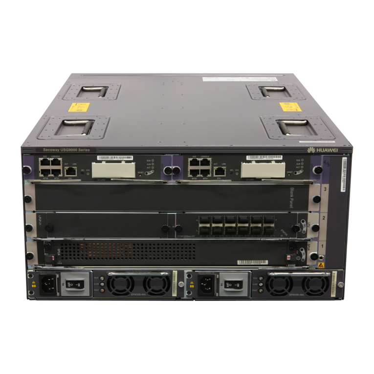
  9. Huawei USG9500 Series Installation instructions

Huawei USG9500 Series Installation instructions

HUAWEI USG9500 Series
Terabit-level Next-Generation Firewall
Hardware Guide
Issue
01
Date
2017-03-13
HUAWEI TECHNOLOGIES CO., LTD.
Issue 01 (2017-03-13)
Huawei Proprietary and Confidential
Copyright © Huawei Technologies Co., Ltd.
i
Copyright © Huawei Technologies Co., Ltd. 2017. All rights reserved.
No part of this document may be reproduced or transmitted in any form or by any means without prior
written consent of Huawei Technologies Co., Ltd.
Trademarks and Permissions
and other Huawei trademarks are trademarks of Huawei Technologies Co., Ltd.
All other trademarks and trade names mentioned in this document are the property of their respective
holders.
Notice
The purchased products, services and features are stipulated by the contract made between Huawei and
the customer. All or part of the products, services and features described in this document may not be
within the purchase scope or the usage scope. Unless otherwise specified in the contract, all statements,
information, and recommendations in this document are provided "AS IS" without warranties, guarantees or
representations of any kind, either express or implied.
The information in this document is subject to change without notice. Every effort has been made in the
preparation of this document to ensure accuracy of the contents, but all statements, information, and
recommendations in this document do not constitute a warranty of any kind, express or implied.
Huawei Technologies Co., Ltd.
Address:
Huawei Industrial Base
Bantian, Longgang
Shenzhen 518129
People's Republic of China
Website:
http://e.huawei.com
HUAWEI USG9500 Series Terabit-level Next-Generation Firewall
Hardware Guide
About This Document
Issue 01 (2017-03-13)
Huawei Proprietary and Confidential
Copyright © Huawei Technologies Co., Ltd.
ii
About This Document
Related Version
The following table lists the product version related to this document.
Product Name
Version
The USG9500 has the
following models:
USG9520
USG9560
USG9580
V500R001C50
Intended Audience
This document describes hardware structure, installation guide, and hardware maintenance.
The content of this document includes the appearance and specifications of the product, the
supported expansion cards, preparation before the installation, installation, cabling, and
hardware replacement.
This document is intended for installation personnel and administrators who install and
maintain USG. The installation personnel or administrators must have experience in the
installation and maintenance of networking devices.
Symbol Conventions
The symbols that may be found in this document are defined as follows.
Symbol
Description
Indicates an imminently hazardous situation which, if not
avoided, will result in death or serious injury.
Indicates a potentially hazardous situation which, if not
avoided, could result in death or serious injury.
HUAWEI USG9500 Series Terabit-level Next-Generation Firewall
Hardware Guide
About This Document
Issue 01 (2017-03-13)
Huawei Proprietary and Confidential
Copyright © Huawei Technologies Co., Ltd.
iii
Symbol
Description
Indicates a potentially hazardous situation which, if not
avoided, may result in minor or moderate injury.
Indicates a potentially hazardous situation which, if not
avoided, could result in equipment damage, data loss,
performance deterioration, or unanticipated results.
NOTICE is used to address practices not related to personal
injury.
Calls attention to important information, best practices and
tips.
NOTE is used to address information not related to
personal injury, equipment damage, and environment
deterioration.
Command Conventions
The command conventions that may be found in this document are defined as follows.
Convention
Description
Boldface
The keywords of a command line are in boldface.
Italic
Command arguments are in italics.
[ ]
Items (keywords or arguments) in brackets [ ] are optional.
{ x | y | ... }
Optional items are grouped in braces and separated by
vertical bars. One item is selected.
[ x | y | ... ]
Optional items are grouped in brackets and separated by
vertical bars. One item is selected or no item is selected.
{ x | y | ... } *
Optional items are grouped in braces and separated by
vertical bars. A minimum of one item or a maximum of all
items can be selected.
[ x | y | ... ] *
Optional items are grouped in brackets and separated by
vertical bars. Several items or no item can be selected.
&<1-n>
The parameter before the & sign can be repeated 1 to n
times.
#
A line starting with the # sign is comments.
HUAWEI USG9500 Series Terabit-level Next-Generation Firewall
Hardware Guide
About This Document
Issue 01 (2017-03-13)
Huawei Proprietary and Confidential
Copyright © Huawei Technologies Co., Ltd.
iv
GUI Conventions
The GUI conventions that may be found in this document are defined as follows.
Convention
Description
Boldface
Buttons, menus, parameters, tabs, window, and dialog titles
are in boldface. For example, click OK.
>
Multi-level menus are in boldface and separated by the ">"
signs. For example, choose File > Create > Folder.
Update History
Updates between document issues are cumulative. Therefore, the latest document issue
contains all updates made in previous issues.
Updates in Issue 01 (2017-03-13)
Initial commercial release.
HUAWEI USG9500 Series Terabit-level Next-Generation Firewall
Hardware Guide
Contents
Issue 01 (2017-03-13)
Huawei Proprietary and Confidential
Copyright © Huawei Technologies Co., Ltd.
v
Contents
About This Document.................................................................................................................... ii
1 Hardware Overview .....................................................................................................................1
1.1 USG9580 ......................................................................................................................................................................1
1.1.1 Device Overview .......................................................................................................................................................1
1.1.2 Components of the USG9580....................................................................................................................................3
1.1.3 Slots Layout and Supported Boards...........................................................................................................................6
1.1.4 Power Supply System..............................................................................................................................................10
1.1.4.1 Features and Distributed Architecture of the Power Supply System ....................................................................10
1.1.4.2 DC Power Supply System..................................................................................................................................... 11
1.1.4.3 AC Power Supply System.....................................................................................................................................15
1.1.5 Heat Dissipation System..........................................................................................................................................19
1.1.5.1 System Air Channel ..............................................................................................................................................19
1.1.5.2 Fan Module...........................................................................................................................................................20
1.1.5.3 Air Filter ...............................................................................................................................................................22
1.1.6 Switch Fabric...........................................................................................................................................................23
1.1.7 Control Plane...........................................................................................................................................................24
1.1.8 Technical Specifications ..........................................................................................................................................25
1.2 USG9560 ....................................................................................................................................................................28
1.2.1 Device Overview .....................................................................................................................................................28
1.2.2 Components of the USG9560..................................................................................................................................30
1.2.3 Slots Layout and Supported Boards.........................................................................................................................32
1.2.4 Power Supply System..............................................................................................................................................35
1.2.4.1 Features and Distributed Architecture of the Power Supply System ....................................................................35
1.2.4.2 DC Power Supply System.....................................................................................................................................36
1.2.4.3 AC Power Supply System.....................................................................................................................................38
1.2.5 Heat Dissipation System..........................................................................................................................................42
1.2.5.1 System Air Channel ..............................................................................................................................................42
1.2.5.2 Fan Module...........................................................................................................................................................43
1.2.5.3 Air Filter ...............................................................................................................................................................45
1.2.6 Switch Frabric..........................................................................................................................................................45
1.2.7 Control Plane...........................................................................................................................................................47
1.2.8 Technical Specifications ..........................................................................................................................................48
HUAWEI USG9500 Series Terabit-level Next-Generation Firewall
Hardware Guide
Contents
Issue 01 (2017-03-13)
Huawei Proprietary and Confidential
Copyright © Huawei Technologies Co., Ltd.
vi
1.3 USG9520 ....................................................................................................................................................................50
1.3.1 Device Overview .....................................................................................................................................................50
1.3.2 Components of the USG9520..................................................................................................................................51
1.3.3 Slots Layout and Supported Boards.........................................................................................................................54
1.3.4 Power Supply System..............................................................................................................................................57
1.3.4.1 Features of the Power Supply System...................................................................................................................57
1.3.4.2 DC Power Supply System.....................................................................................................................................58
1.3.4.3 AC Power Supply System.....................................................................................................................................59
1.3.5 Heat Dissipation System..........................................................................................................................................63
1.3.5.1 System Air Channel ..............................................................................................................................................63
1.3.5.2 Fan Module...........................................................................................................................................................64
1.3.5.3 Air Filter ...............................................................................................................................................................66
1.3.6 Control Plane...........................................................................................................................................................67
1.3.7 Technical Specifications ..........................................................................................................................................68
1.4 Boards.........................................................................................................................................................................70
1.4.1 Board Overview.......................................................................................................................................................70
1.4.1.1 Types and Mappings of Boards.............................................................................................................................70
1.4.1.2 Board Structure.....................................................................................................................................................88
1.4.1.3 Rules for Numbering Slots and Interfaces ............................................................................................................89
1.4.2 MPUs and SRUs......................................................................................................................................................92
1.4.2.1 EKEX16-FWCD00MPUB00................................................................................................................................92
1.4.2.2 E8KE-X8-SRUA-200...........................................................................................................................................95
1.4.2.3 E8KE-X3-MPU ....................................................................................................................................................99
1.4.2.4 MPUD.................................................................................................................................................................102
1.4.3 SFUs ......................................................................................................................................................................105
1.4.3.1 E8KE-X16-SFUC-200SP ...................................................................................................................................105
1.4.3.2 E8KE-X8-SFUC-200..........................................................................................................................................107
1.4.4 SPUs and SPCs......................................................................................................................................................108
1.4.4.1 X3 SPU (SPU-X3-B)..........................................................................................................................................108
1.4.4.2 X3 SPU (SPU-X3-B2)........................................................................................................................................109
1.4.4.3 X8&X16 SPU (SPU-X8X16-B)......................................................................................................................... 111
1.4.4.4 Firewall Service Processing Unit (SPU-X3-20-O-E8KE, for USG9520)........................................................... 112
1.4.4.5 Firewall Service Processing Unit (SPUA-20-O-M, for USG9520)....................................................................114
1.4.4.6 Firewall Service Processing Unit (SPUB-20-O-M, for USG9520) .................................................................... 115
1.4.4.7 Firewall Service Processing Unit (SPU-X8X16-20-O-E8KE, for USG9560/USG9580)................................... 117
1.4.4.8 Firewall Service Processing Unit (SPUA-20-O-H, for USG9560/USG9580).................................................... 118
1.4.4.9 Firewall Service Processing Unit (SPUB-20-O-H, for USG9560/USG9580)....................................................120
1.4.4.10 Firewall Performance Expansion Card (SPC-20-O-E8KE)..............................................................................122
1.4.4.11 Firewall Performance Expansion Card (SPCA-20-O-H&M) ...........................................................................123
1.4.4.12 Firewall Performance Expansion Card (SPCB-20-O-H&M)............................................................................124
1.4.4.13 Application Security Service Processing Card (SPC-APPSEC-FW)................................................................125
1.4.4.14 Application Security Service Processing Card (SPC-IPS-20)...........................................................................127
HUAWEI USG9500 Series Terabit-level Next-Generation Firewall
Hardware Guide
Contents
Issue 01 (2017-03-13)
Huawei Proprietary and Confidential
Copyright © Huawei Technologies Co., Ltd.
vii
1.4.5 LPUF-240 and FPICs ............................................................................................................................................128
1.4.5.1 LPUF-240...........................................................................................................................................................128
1.4.5.2 20-Port 10/100/1000Base-RJ45 FPIC (FW-20X1G-RJ45).................................................................................130
1.4.5.3 24-Port 100/1000 Base-X-SFP FPIC (E8KE-X-101-24XGE-SFP)....................................................................131
1.4.5.4 5-Port 10GBase LAN/WAN-SFP+ FPIC A (E8KE-X-101-5X10GE-SFP+)......................................................133
1.4.5.5 6*10GE SFP+ Daughter Card (FW-6X10GE-SFP+)..........................................................................................134
1.4.5.6 12*10GE SFP+ Daughter Card (FW-12X10GE-SFP+)......................................................................................135
1.4.5.7 3-Port 40GBase QSFP+ FPIC (FW-3X40G-QSFP+).........................................................................................137
1.4.5.8 1-Port 40GBase LAN-CFP FPIC A (E8KE-X-101-1X40GE-CFP)....................................................................138
1.4.5.9 1*100GE CFP Daughter Card (FW-1X100GE-CFP) .........................................................................................140
1.4.6 LPUF-120 and FPICs ............................................................................................................................................141
1.4.6.1 LPUF-120...........................................................................................................................................................141
1.4.6.2 20-Port 10/100/1000Base-RJ45 FPIC (FW-20X1G-RJ45).................................................................................143
1.4.6.3 24-Port 100/1000 Base-X-SFP FPIC (E8KE-X-101-24XGE-SFP)....................................................................144
1.4.6.4 5-Port 10GBase LAN/WAN-SFP+ FPIC A (E8KE-X-101-5X10GE-SFP+)......................................................146
1.4.6.5 6*10GE SFP+ Daughter Card (FW-6X10GE-SFP+)..........................................................................................147
1.4.6.6 12*10GE SFP+ Daughter Card (FW-12X10GE-SFP+)......................................................................................148
1.4.6.7 3-Port 40GBase QSFP+ FPIC (FW-3X40G-QSFP+).........................................................................................150
1.4.6.8 1-Port 40GBase LAN-CFP FPIC A (E8KE-X-101-1X40GE-CFP)....................................................................151
1.4.6.9 1*100GE CFP Daughter Card (FW-1X100GE-CFP) .........................................................................................153
1.4.7 LPUF-101 and FPICs ............................................................................................................................................154
1.4.7.1 LPUF-101...........................................................................................................................................................154
1.4.7.2 24-Port 100/1000 Base-X-SFP FPIC (E8KE-X-101-24XGE-SFP)....................................................................156
1.4.7.3 4-Port 10G Base LAN -SFP+ FPIC (E8KE-X-101-4X10GE-SFP+)..................................................................157
1.4.7.4 5-Port 10GBase LAN/WAN-SFP+ FPIC A (E8KE-X-101-5X10GE-SFP+)......................................................159
1.4.7.5 1-Port 40GBase LAN-CFP FPIC A (E8KE-X-101-1X40GE-CFP)....................................................................160
1.4.8 LPUF-40-A and FPIC............................................................................................................................................162
1.4.8.1 LPUF-40-A.........................................................................................................................................................162
1.4.8.2 20-Port 100/1000Base-X-SFP Flexible Card (P40-20xGE/FE-SFP)..................................................................163
1.4.8.3 2-Port 10GBase LAN/WAN-XFP Flexible Card (P40-2x10GBase LAN/WAN-XFP).......................................165
1.4.8.4 4-port 10GBase LAN/WAN-XFP FPIC (P40-4x10GBase LAN/WAN-XFP) ....................................................166
1.4.9 LPUF-21 and FPIC................................................................................................................................................168
1.4.9.1 LPUF-21.............................................................................................................................................................168
1.4.9.2 12-port 10Base-T/100Base-TX/1000Base-T-RJ45 FPIC (12x10/100/1000Base-TX-RJ45) ..............................169
1.4.9.3 12-port 100Base-FX/1000Base-X-SFP FPIC (12x100/1000Base-SFP).............................................................171
1.4.9.4 1-port OC-192c/STM-64c POS-XFP FPIC (1 x OC-192c/STM-64c POS-XFP)...............................................172
1.4.9.5 1-port 10GBase LAN/WAN-XFP FPIC (1 x 10GBase LAN/WAN) ..................................................................174
1.4.9.6 4-Port 10GBase WAN/LAN-XFP FPIC (4x10GBase LAN/WAN) ....................................................................175
1.4.10 1-Port 100GBase-CFP Integrated Line Processing Unit (LPUI-101)..................................................................177
1.5 Optical/Electrical Module.........................................................................................................................................178
1.5.1 1 Gbit/s Electrical Transceiver...............................................................................................................................178
1.5.2 1.25 Gbit/s SFP/eSFP Optical Module...................................................................................................................180
HUAWEI USG9500 Series Terabit-level Next-Generation Firewall
Hardware Guide
Contents
Issue 01 (2017-03-13)
Huawei Proprietary and Confidential
Copyright © Huawei Technologies Co., Ltd.
viii
1.5.3 10 Gbit/s XFP Optical Module ..............................................................................................................................185
1.5.4 10 Gbit/s SFP+ Optical Module.............................................................................................................................191
1.5.5 40 Gbit/s CFP Optical Modules.............................................................................................................................196
1.5.6 40 Gbit/s QSFP+ Optical Module..........................................................................................................................199
1.5.7 100 Gbit/s CFP Optical Modules...........................................................................................................................203
2 Hardware Installation ..............................................................................................................207
2.1 Installation Preparation.............................................................................................................................................207
2.1.1 Preparing Technical Documents ............................................................................................................................207
2.1.2 Preparing Tools and Meters ...................................................................................................................................208
2.1.3 Checking the Installation Environment .................................................................................................................209
2.1.4 Unpacking and Checking the Products..................................................................................................................210
2.1.4.1 Checking the Package Container ........................................................................................................................210
2.1.4.2 Unpacking the Wooden Case .............................................................................................................................. 211
2.1.4.3 Unpacking the Carton.........................................................................................................................................215
2.1.4.4 Checking the Boards...........................................................................................................................................216
2.2 Installing USG9580 ..................................................................................................................................................217
2.2.1 Preparing the Site...................................................................................................................................................217
2.2.2 Installing the Chassis into the Cabinet...................................................................................................................218
2.2.3 Installing the PGND Cable ....................................................................................................................................222
2.2.4 Installing Boards and Subcards..............................................................................................................................223
2.2.5 Installing Chassis Components..............................................................................................................................226
2.2.6 Installing Power Cables-DC Power Distribution...................................................................................................228
2.2.7 Installing Power Cables-AC Power Distribution...................................................................................................231
2.2.8 Connecting Network Cables..................................................................................................................................234
2.2.9 Connecting Optical Fibers .....................................................................................................................................237
2.2.10 Checking After Installation..................................................................................................................................240
2.2.11 Powering On the USG9580-DC Power Distribution ...........................................................................................241
2.2.12 Powering On the USG9580-AC Power Distribution ...........................................................................................244
2.3 Installing USG9560 ..................................................................................................................................................248
2.3.1 Preparing the Site...................................................................................................................................................248
2.3.2 Installing the Chassis into the Cabinet...................................................................................................................250
2.3.3 Installing the PGND Cable ....................................................................................................................................254
2.3.4 Installing Boards and Subcards..............................................................................................................................255
2.3.5 Installing Chassis Components..............................................................................................................................257
2.3.6 Installing Power Cables-DC Power Distribution...................................................................................................259
2.3.7 Installing Power Cables-AC Power Distribution...................................................................................................262
2.3.8 Connecting Network Cables..................................................................................................................................265
2.3.9 Connecting Optical Fibers .....................................................................................................................................267
2.3.10 Checking After Installation..................................................................................................................................270
2.3.11 Powering On the USG9560-DC Power Distribution ...........................................................................................271
2.3.12 Powering On the USG9560-AC Power Distribution ...........................................................................................274
HUAWEI USG9500 Series Terabit-level Next-Generation Firewall
Hardware Guide
Contents
Issue 01 (2017-03-13)
Huawei Proprietary and Confidential
Copyright © Huawei Technologies Co., Ltd.
ix
2.4 Installing USG9520 ..................................................................................................................................................277
2.4.1 Preparing the Site...................................................................................................................................................277
2.4.2 Installing Cable Racks and Mounting Ears............................................................................................................279
2.4.3 Installing the Chassis into the Cabinet...................................................................................................................280
2.4.4 Installing the PGND Cable ....................................................................................................................................282
2.4.5 Installing Boards and Subcards..............................................................................................................................283
2.4.6 Installing Power Cables-DC Power Distribution...................................................................................................285
2.4.7 Installing Power Cables-AC Power Distribution...................................................................................................288
2.4.8 Connecting Network Cables..................................................................................................................................291
2.4.9 Connecting Optical Fibers .....................................................................................................................................293
2.4.10 Checking After Installation..................................................................................................................................295
2.4.11 Powering On the USG9520-DC Power Distribution ...........................................................................................297
2.4.12 Powering On the USG9520-AC Power Distribution ...........................................................................................299
2.5 Guide to Power Distribution Design.........................................................................................................................302
2.5.1 Guide to Power Distribution Design of the USG9580...........................................................................................302
2.5.1.1 Guide to the DC Power Distribution...................................................................................................................302
2.5.1.2 Guide to the AC Power Distribution...................................................................................................................304
2.5.2 Guide to Power Distribution Design of the USG9560...........................................................................................306
2.5.2.1 Guide to the DC Power Distribution...................................................................................................................306
2.5.2.2 Guide to the AC Power Distribution...................................................................................................................309
2.5.3 Guide to Power Distribution Design of the USG9520...........................................................................................310
2.5.3.1 Guide to the DC Power Distribution...................................................................................................................310
2.5.3.2 Guide to the AC Power Distribution...................................................................................................................312
3 Hardware Maintenance............................................................................................................314
3.1 Replacing Boards......................................................................................................................................................314
3.1.1 Replacing an MPU/SRU........................................................................................................................................314
3.1.2 Replacing an SFU..................................................................................................................................................318
3.1.3 Replacing an LPU..................................................................................................................................................322
3.1.4 Replacing an FPIC of the LPU ..............................................................................................................................326
3.1.5 Replacing an SPU..................................................................................................................................................329
3.1.6 Replacing the SPC of the SPU...............................................................................................................................333
3.2 Expanding SPU Capacities .......................................................................................................................................336
3.2.1 Expanding SPU Capacities for the Active and Standby FWs in Hot Standby Scenarios (for V500R001C50 and
Later Versions)................................................................................................................................................................336
3.2.2 Expanding SPC Capacities for the Active and Standby FWs in Hot Standby Scenarios (for V500R001C50 and
Later Versions)................................................................................................................................................................342
3.3 Replacing a Fan Frame .............................................................................................................................................348
3.3.1 Replacing the Fan Module of the USG9580..........................................................................................................348
3.3.2 Replacing the Fan Module of the USG9560..........................................................................................................350
3.3.3 Replacing the Fan Frame of the USG9520............................................................................................................353
3.4 Replacing a Power Module.......................................................................................................................................356
3.4.1 Replacing the DC PEM of the USG9580...............................................................................................................356
HUAWEI USG9500 Series Terabit-level Next-Generation Firewall
Hardware Guide
Contents
Issue 01 (2017-03-13)
Huawei Proprietary and Confidential
Copyright © Huawei Technologies Co., Ltd.
x
3.4.2 Replacing the DC PEM of the USG9560...............................................................................................................360
3.4.3 Replacing a DC Power Module of USG9520 ........................................................................................................363
3.4.4 Replacing an AC Power Module of USG9520 ......................................................................................................367
3.5 Replacing a CF Card.................................................................................................................................................372
3.5.1 Replacing CF Card 1 .............................................................................................................................................372
3.5.2 Replacing CF Card 2 .............................................................................................................................................374
3.6 Replacing an Optical Module ...................................................................................................................................377
3.7 Replacing an Air Filter..............................................................................................................................................381
3.7.1 Replacing the Air Filter of the USG9580...............................................................................................................381
3.7.2 Replacing the Air Filter of the USG9560...............................................................................................................384
3.7.3 Replacing the Air Filter of the USG9520...............................................................................................................386
3.8 Replacing Cables ......................................................................................................................................................388
3.8.1 Replacing a Power Cable.......................................................................................................................................388
3.8.2 Replacing a Network Cable ...................................................................................................................................389
3.8.3 Replacing an Optical Cable ...................................................................................................................................391
A Appendix ...................................................................................................................................393
A.1 Cable........................................................................................................................................................................393
A.1.1 DC Power Cable ...................................................................................................................................................393
A.1.1.1 DC Power Cable of the USG9580 .....................................................................................................................393
A.1.1.2 DC Power Cable of the USG9560 .....................................................................................................................397
A.1.1.3 DC Power Cable of the USG9520 .....................................................................................................................401
A.1.2 AC Power Cable....................................................................................................................................................403
A.1.2.1 AC Power Cable of the USG9580......................................................................................................................403
A.1.2.2 AC Power Cable of the USG9560......................................................................................................................405
A.1.2.3 AC Power Cable of the USG9520......................................................................................................................406
A.1.3 PGND Cable .........................................................................................................................................................408
A.1.4 Console Cable.......................................................................................................................................................410
A.1.5 Auxiliary Port Cable ............................................................................................................................................. 411
A.1.6 Ethernet Cable.......................................................................................................................................................413
A.1.7 Optical Fiber .........................................................................................................................................................418
A.2 On-site Cable Assembly and Installation.................................................................................................................421
A.2.1 Cable Assembling Precautions..............................................................................................................................421
A.2.2 Assembling Power Cables.....................................................................................................................................422
A.2.2.1 Assembling the OT Terminal and the Power Cable ...........................................................................................422
A.2.2.2 Assembling the JG Terminal and the Power Cable............................................................................................425
A.2.2.3 Assembling the Cord End Terminal and the Power Cable .................................................................................428
A.2.3 Assembling Ethernet Cables .................................................................................................................................431
A.2.3.1 Assembling the Shielded RJ45 Connector and the Ethernet Cable....................................................................431
A.2.3.2 Assembling the Unshielded RJ45 Connector and the Ethernet Cable................................................................437
A.2.3.3 Checking the Appearance of Metal Contact Strips ............................................................................................439
A.2.3.4 Testing the Connection of Assembled Cables ....................................................................................................442
HUAWEI USG9500 Series Terabit-level Next-Generation Firewall
Hardware Guide
Contents
Issue 01 (2017-03-13)
Huawei Proprietary and Confidential
Copyright © Huawei Technologies Co., Ltd.
xi
A.3 Environmental Requirements for Device Running..................................................................................................445
A.3.1 Requirements for Selecting a Site for an Equipment Room .................................................................................445
A.3.2 Equipment Room Layout......................................................................................................................................446
A.3.3 Construction Requirements for the Equipment Room ..........................................................................................446
A.3.4 Requirements for Temperature, Humidity, and Altitude .......................................................................................448
A.3.5 Requirements for Neatness ...................................................................................................................................448
A.3.6 Requirements for Corrosive Gases .......................................................................................................................449
A.3.7 Requirements for ESD Prevention........................................................................................................................450
A.3.8 Electromagnetism Requirements for the Equipment Room..................................................................................450
A.3.9 Requirements for Lightning Proof Grounding......................................................................................................450
A.3.10 Requirements for Power Supply .........................................................................................................................452
A.4 Equipment Grounding Specifications ......................................................................................................................455
A.4.1 General Grounding Specifications........................................................................................................................455
A.4.2 Grounding Specifications for an Equipment Room..............................................................................................455
A.4.3 Grounding Specifications for the Device..............................................................................................................456
A.4.4 Grounding Specifications for Communications Power Supply ............................................................................456
A.4.5 Grounding Specifications for Signal Cables.........................................................................................................457
A.4.6 Specifications for Laying Out Grounding Cables.................................................................................................458
A.5 Engineering Labels for Cables.................................................................................................................................458
A.5.1 Introduction to Labels...........................................................................................................................................459
A.5.1.1 Label Materials ..................................................................................................................................................459
A.5.1.2 Type and Structure .............................................................................................................................................459
A.5.1.3 Label Printing ....................................................................................................................................................461
A.5.1.4 Writing Labels....................................................................................................................................................463
A.5.1.5 Affixing Labels ..................................................................................................................................................464
A.5.1.6 Contents of Engineering Labels.........................................................................................................................466
A.5.1.7 Precautions for Using Engineering Labels.........................................................................................................467
A.5.2 Engineering Labels for Optical Fibers..................................................................................................................467
A.5.2.1 Labels for the Optical Fibers Connecting Devices.............................................................................................467
A.5.2.2 Labels for the Optical Fibers Connecting the Device and an ODF....................................................................469
A.5.3 Engineering Labels for Network Cables...............................................................................................................470
A.5.4 Engineering Labels for Trunk Cables ...................................................................................................................472
A.5.4.1 Engineering Labels for Trunk Cables Between Devices....................................................................................472
A.5.4.2 Engineering Labels for Trunk Cables Between the Device and a DDF .............................................................474
A.5.5 Engineering Labels for User Cables .....................................................................................................................475
A.5.6 Engineering Labels for Power Cables...................................................................................................................476
A.5.6.1 Engineering Labels for DC Power Cables .........................................................................................................476
A.5.6.2 Engineering Labels for AC Power Cables .........................................................................................................478
A.6 Requirements on Customers' Cabinets Purchased from Other Vendors...................................................................479
HUAWEI USG9500 Series Terabit-level Next-Generation Firewall
Hardware Guide
Contents
Issue 01 (2017-03-13)
Huawei Proprietary and Confidential
Copyright © Huawei Technologies Co., Ltd.
1
1 Hardware Overview
1.1 USG9580
The USG9580 is a 32 U device. It employs an integrated chassis and provides 16 LPU/SPU
slots. Its MPUs, SFUs, power modules, and fans work in redundancy mode.
1.1.1 Device Overview
This section describes the appearance and hardware system features of the USG9580.
Appearance
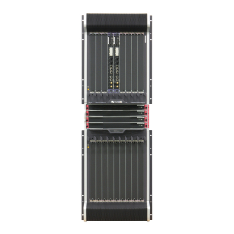
The USG9580 has an integrated chassis, and adopts a centralized routing engine and a
distributed forwarding architecture.
Figure 1-1 shows the chassis of the USG9580.
HUAWEI USG9500 Series Terabit-level Next-Generation Firewall
Hardware Guide
Contents
Issue 01 (2017-03-13)
Huawei Proprietary and Confidential
Copyright © Huawei Technologies Co., Ltd.
2
Figure 1-1 Appearance of the chassis
System Features
The USG9580 provides the following system features:
Unblocked switching network that can be upgraded, with switching capacity at the Tbit/s
level
Distributed hardware-based forwarding and fast service deployment
Compact structure to increase interface density
Normalized design of system components
Separation of the control channel, service channel, and monitoring channel to ensure
non-blacking control channels and monitoring channels
Carrier-class high reliability and manageability
HUAWEI USG9500 Series Terabit-level Next-Generation Firewall
Hardware Guide
Contents
Issue 01 (2017-03-13)
Huawei Proprietary and Confidential
Copyright © Huawei Technologies Co., Ltd.
3
Shielding at the modular level to meet Electro Magnetic Compatibility (EMC)
requirements
Hot-swappable boards, power modules, and fans
U-shaped air channels to improve system heat dissipation
Distributed power supply to enhance power supply capability for a single chassis
200-mm fans with a power filter module
MPUs in 1:1 backup mode
SFUs in load balancing mode
Backup for key components such as power modules, fan modules, clocks, and
management buses
Protection against incorrect of boards
Queries about alarm prompts, alarm indications, running status, and alarm status of the
voltage and ambient temperature
1.1.2 Components of the USG9580
The section describes main components on the front and rear panels of the USG9580.
The USG9580 has an integrated chassis, Figure 1-2 and Figure 1-3 show the architecture and
main components of the USG9580.
HUAWEI USG9500 Series Terabit-level Next-Generation Firewall
Hardware Guide
Contents
Issue 01 (2017-03-13)
Huawei Proprietary and Confidential
Copyright © Huawei Technologies Co., Ltd.
4
Front Panel
Figure 1-2 USG9580 Front Panel
No.
Name
Description
1
Air filter
The USG9580 has three air filters that are deployed on the air intake
vents of the upper and lower air channels and air intake vent at the left
side of the SFU area to protect the device against dust.
2
MPU
The Main Processing Unit (MPU) on the USG9580 is in charge of
system control and route information learning. It is the central control
unit of the device. The USG9580 MPU uses the 1:1 backup
mechanism. When the active MPU is faulty, the standby MPU
immediately takes over the work. The backup mechanism ensures the
proper running of services.
3
LPU/SPU
slot
It holds an LPU or SPU.
4
SFU
The SFUs of the USG9580 are responsible for data switching of the
entire system. The USG9580 has four SFUs that work in 3+1 backup
HUAWEI USG9500 Series Terabit-level Next-Generation Firewall
Hardware Guide
Contents
Issue 01 (2017-03-13)
Huawei Proprietary and Confidential
Copyright © Huawei Technologies Co., Ltd.
5
No.
Name
Description
mode for load balancing.
5
ESD jack
The equipment end of the wrist strap is inserted into the ESD jack. For
the wrist strap to be effective, ensure that the device is already
grounded.
6
Front
cable rack
It is used to deploy optical fibers and cables. The front cable rack is
divided into the upper and lower racks. The logo of the upper cable
rack is "HUAWEI", the logo of the lower cable rack is "USG9500
Series".
Rear Panel
Figure 1-3 USG9580 Rear Panel
No.
Name
Description
1
Fan
The USG9580 has four fan modules, each two arranged side by side.
HUAWEI USG9500 Series Terabit-level Next-Generation Firewall
Hardware Guide
Contents
Issue 01 (2017-03-13)
Huawei Proprietary and Confidential
Copyright © Huawei Technologies Co., Ltd.
6
No.
Name
Description
module
The fan modules are deployed on the air exhaust vents of the upper
and lower air channels respectively and work in 2+2 backup mode.
2
PEM
module
The USG9580 uses eight PEM power modules for DC power supply.
The USG9580 backplane is divided into four areas, each of which has
two PEM power inputs. These eight power inputs work in 4+4 backup
mode.
If the USG9580 uses the AC power supply, two additional external AC
power chassises are required.
3
Rear cable
rack
It is used to deploy optical fibers and cables. There are four rear cable
racks on the upper parts of the power modules.
4
Power
supply
areas
Power supply areas of the eight PEM power modules on the USG9580.
5
Protective
ground
terminal
The OT terminal of the ground cable is connected to the protective
ground terminal of the device, and the other terminal of the ground
cable is connected to the ground point of the cabinet or workbench or
the ground bar of the equipment room.
1.1.3 Slots Layout and Supported Boards
This section describes the layout of slots and supported boards on the USG9580.
Slots Layout
Figure 1-4shows the slot layout on the USG9580.
HUAWEI USG9500 Series Terabit-level Next-Generation Firewall
Hardware Guide
Contents
Issue 01 (2017-03-13)
Huawei Proprietary and Confidential
Copyright © Huawei Technologies Co., Ltd.
7
Figure 1-4 Slot layout on the USG9580
Table 1-1 describes the slot layout on the USG9580.
Table 1-1 Table 1 Board distribution in the board cage of the USG9580
Slot
Name
Slot
Number
Quant
ity
Slot Height
Remarks
LPU/SPU
1 to 16
16
41 mm (1.6
inches)
These slots are used to hold LPUs
or SPUs.
MPU
17 to 18
2
41 mm (1.6
inches)
These slots hold MPUs that work
in 1:1 backup mode.
SFU
19 to 22
4
41 mm (1.6
inches)
These slots are used to hold SFUs.
Supported Boards
Table 1-2 lists the specifications of boards supported by the USG9580.
Table 1-2 Supported boards by the USG9580
Type
BOM
Description
Hot
Swap
MPU
0305G06U
1.4.2.1 EKEX16-FWCD00MPUB00
Yes
SFU
0305G08Q
1.4.3.1 E8KE-X16-SFUC-200SP
Yes
SPUs and SPCs
03056638
1.4.4.3 X8&X16 SPU (SPU-X8X16-B)
Yes
HUAWEI USG9500 Series Terabit-level Next-Generation Firewall
Hardware Guide
Contents
Issue 01 (2017-03-13)
Huawei Proprietary and Confidential
Copyright © Huawei Technologies Co., Ltd.
8
Type
BOM
Description
Hot
Swap
0305G09U
1.4.4.7 Firewall Service Processing Unit
(SPU-X8X16-20-O-E8KE, for
USG9560/USG9580)
Yes
03057426
1.4.4.8 Firewall Service Processing Unit
(SPUA-20-O-H, for USG9560/USG9580)
Yes
03057520
1.4.4.9 Firewall Service Processing Unit
(SPUB-20-O-H, for USG9560/USG9580)
Yes
0305G09V
1.4.4.10 Firewall Performance Expansion
Card (SPC-20-O-E8KE)
Yes
03057429
1.4.4.11 Firewall Performance Expansion
Card (SPCA-20-O-H&M)
Yes
03057522
1.4.4.12 Firewall Performance Expansion
Card (SPCB-20-O-H&M)
Yes
03056688
1.4.4.13 Application Security Service
Processing Card (SPC-APPSEC-FW)
Yes
03056639
1.4.4.14 Application Security Service
Processing Card (SPC-IPS-20)
Yes
LPUF-240 and
FPIC
03056683
1.4.5.1 LPUF-240
Yes
03056890
1.4.5.2 20-Port 10/100/1000Base-RJ45
FPIC (FW-20X1G-RJ45)
No
03056633
1.4.5.3 24-Port 100/1000 Base-X-SFP
FPIC (E8KE-X-101-24XGE-SFP)
No
03056632
1.4.5.4 5-Port 10GBase LAN/WAN-SFP+
FPIC A (E8KE-X-101-5X10GE-SFP+)
No
03056684
1.4.5.5 6*10GE SFP+ Daughter Card
(FW-6X10GE-SFP+)
No
03056686
1.4.5.6 12*10GE SFP+ Daughter Card
(FW-12X10GE-SFP+)
No
03056848
1.4.5.7 3-Port 40GBase QSFP+ FPIC
(FW-3X40G-QSFP+)
No
03056631
1.4.5.8 1-Port 40GBase LAN-CFP FPIC A
(E8KE-X-101-1X40GE-CFP)
No
03056685
1.4.5.9 1*100GE CFP Daughter Card
(FW-1X100GE-CFP)
No
LPUF-120 and
FPIC
03056682
1.4.6.1 LPUF-120
Yes
03056890
1.4.6.2 20-Port 10/100/1000Base-RJ45
FPIC (FW-20X1G-RJ45)
No
03056633
1.4.6.3 24-Port 100/1000 Base-X-SFP
No

Other manuals for USG9500 Series

1

This manual suits for next models

4

Other Huawei Firewall manuals

Huawei USG6306 User manual

Huawei

Huawei USG6306 User manual

Huawei USG6000E Series Installation instructions

Huawei

Huawei USG6000E Series Installation instructions

Huawei USG9500 Series Installation instructions

Huawei

Huawei USG9500 Series Installation instructions

Huawei HiSecEngine USG6000F Series User manual

Huawei

Huawei HiSecEngine USG6000F Series User manual

Huawei USG6000 Series Installation instructions

Huawei

Huawei USG6000 Series Installation instructions

Huawei Eudemon8000E Series User manual

Huawei

Huawei Eudemon8000E Series User manual

Huawei NIP6830 User manual

Huawei

Huawei NIP6830 User manual

Huawei Quidway Eudemon 200 User manual

Huawei

Huawei Quidway Eudemon 200 User manual

Huawei USG6000 Series Installation and operation manual

Huawei

Huawei USG6000 Series Installation and operation manual

Popular Firewall manuals by other brands

Trend Micro GateLock Getting started guide

Trend Micro

Trend Micro GateLock Getting started guide

PaloAlto Networks PA-220R quick start guide

PaloAlto Networks

PaloAlto Networks PA-220R quick start guide

Atlante Informatica AFEL Series user manual

Atlante Informatica

Atlante Informatica AFEL Series user manual

Fortinet FortiGate FortiGate-500A quick start guide

Fortinet

Fortinet FortiGate FortiGate-500A quick start guide

IBM 1G user guide

IBM

IBM 1G user guide

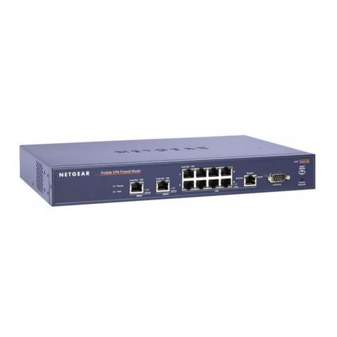
NETGEAR ProSafe FVX538 installation guide

NETGEAR

NETGEAR ProSafe FVX538 installation guide

ZyXEL Communications ZyWALL/USG Series quick start guide

ZyXEL Communications

ZyXEL Communications ZyWALL/USG Series quick start guide

Fortinet FortiGate FortiGate-100A quick start guide

Fortinet

Fortinet FortiGate FortiGate-100A quick start guide

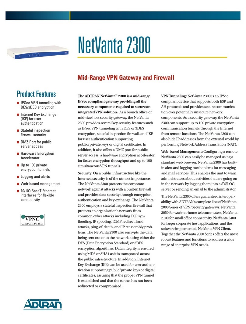
ADTRAN NetVanta 2300 Specifications

ADTRAN

ADTRAN NetVanta 2300 Specifications

Motorola SURFboard SVG2500 user manual

Motorola

Motorola SURFboard SVG2500 user manual

Fortinet FortiMail 3.0 MR4 Cli reference guide

Fortinet

Fortinet FortiMail 3.0 MR4 Cli reference guide

Net-Blocker NB-10 quick start guide

Net-Blocker

Net-Blocker NB-10 quick start guide

Barracuda CloudGen F80 manual

Barracuda

Barracuda CloudGen F80 manual

Fortinet FortiGate 300 Installation &  configuration guide

Fortinet

Fortinet FortiGate 300 Installation & configuration guide

NETGEAR FVL328 - Cable/DSL ProSafe VPN Firewall... Faq

NETGEAR

NETGEAR FVL328 - Cable/DSL ProSafe VPN Firewall... Faq

SonicWALL NSA 2400 Getting started guide

SonicWALL

SonicWALL NSA 2400 Getting started guide

Blue Coat ProxySG 900 Series Maintenance and upgrade guide

Blue Coat

Blue Coat ProxySG 900 Series Maintenance and upgrade guide

Forcepoint 110 Hardware guide

Forcepoint

Forcepoint 110 Hardware guide

manuals.online logo
manuals.online logoBrands
  • About & Mission
  • Contact us
  • Privacy Policy
  • Terms and Conditions

Copyright 2025 Manuals.Online. All Rights Reserved.