Huawei F01T500 User manual

HUAWEI TECHNOLOGIES CO., LTD.
F01T500
Quick Installation Guide
Issue: 07
Date: 2017-05-03

i
Intended Audience
About This Document
Change History
This topic describes how to install the F01T500 cabinet, including installing the cabinet, routing cables, and
powering on the system.
The intended audience is hardware installation engineers.
Changes between document issues are cumulative. Therefore, the latest document issue contains all updates
made in previous issues.
The symbols that may be found in this document are defined as follows.
Symbol Description
Indicates an imminently hazardous situation which, if not avoided, will result in death or
serious injury.
Indicates a potentially hazardous situation which, if not avoided, could result in death or
serious injury.
Indicates a potentially hazardous situation which, if not avoided, may result in minor or
moderate injury.
Indicates a potentially hazardous situation which, if not avoided, could result in equipment
damage, data loss, performance deterioration, or unanticipated results.
NOTICE is used to address practices not related to personal injury.
Calls attention to important information, best practices and tips.
NOTE is used to address information not related to personal injury, equipment damage,
and environment deterioration.
Updates in Issue 07 (2017-05-03)
Based on issue 06 (2017-03-01), this document is updated as follows:
Modified the dimensions of the cabinet bottom.
Symbol Conventions

i
Updates in Issue 01 (2015-03-21)
This is the first release.
Updates in Issue 05 (2016-09-01)
Based on issue 04 (2016-05-30), this document is updated as follows :
Added the description of installing a power meter box for a cabinet .
Added the description of installing a cabinet on an underground base.
Updates in Issue 04 (2016-05-30)
Based on issue 03 (2016-01-14), this document is updated as follows:
Optimized the picture for installing the temporary RPC.
Updates in Issue 03 (2016-01-14)
Based on issue 02 (2015-08-10), this document is updated as follows :
Optimized the layout of the chapters.
Added the operation of the cable sealing bags.
Updates in Issue 02 (2015-08-10)
Based on issue 01 (2015-03-21), this document is updated as follows:
Modified the dimensions of the cabinet bottom.
Added the installation procedure of the temporary RPC.
Added the installation procedure of the battery monitor system.
Installing the Electronic Door Lock System.
Updates in Issue 06 (2017-03-01)
Based on issue 05 (2016-09-01), this document is updated as follows:
Added the AC+RPR power supply.

ii
Contents
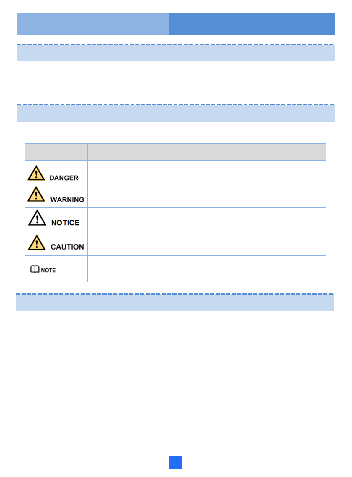
1 Precautions …………….…………………………………………............................………….1
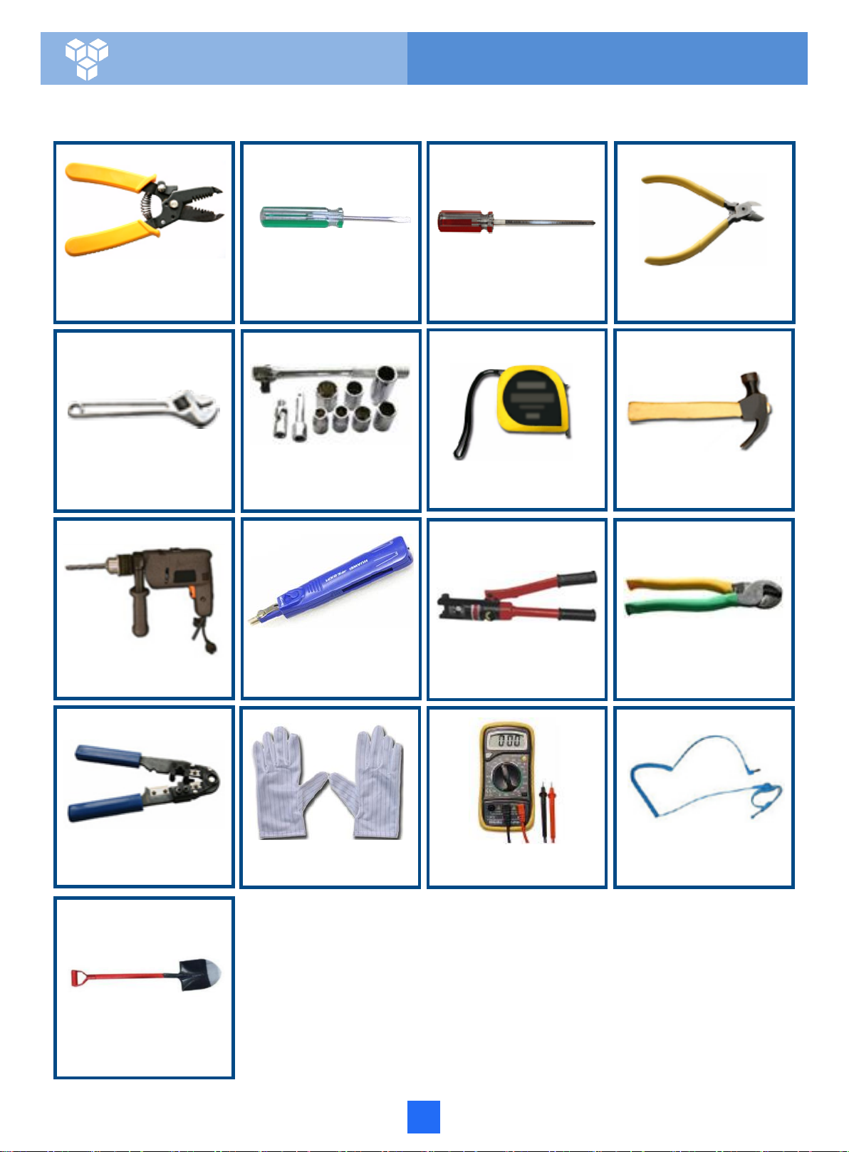
2 Tools for Installation ……………………………………….............................………………….2
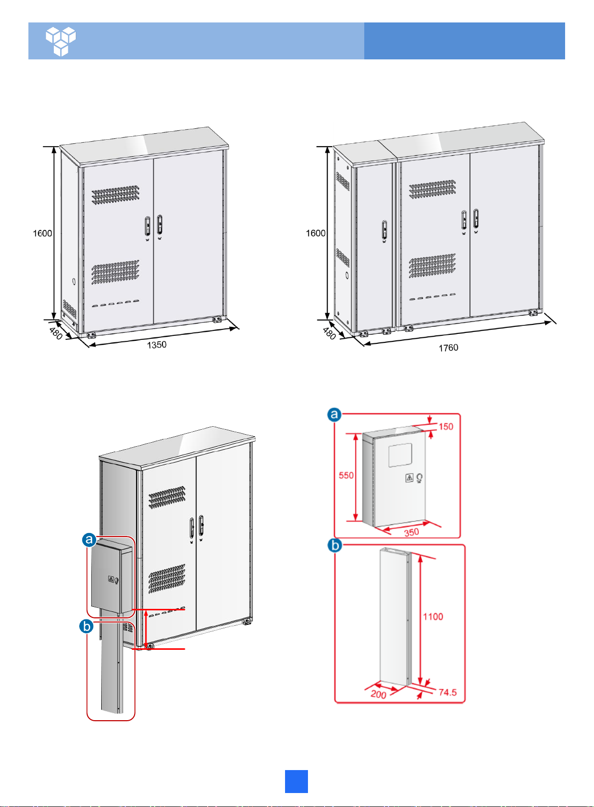
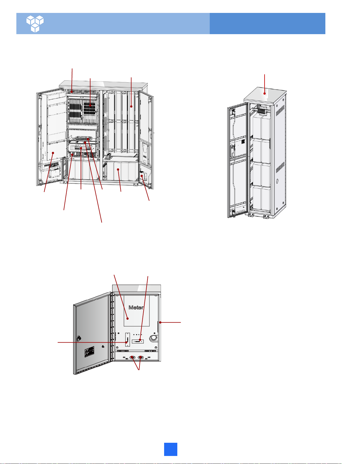
3 Appearance and Structure ……………………………………….............................…………….3
4 Installing the Cabinet on a Concrete Pedestal………….............................…………….8
4.1 Construct the Concrete Pedestal ………………………………………………………….8
4.2 Fastening the Cabinet ….………..................................................................12
5 Installing the Cabinet on an Underground Base……………...............................………..23
5.1 Appearance of the Underground Base............................ ...........................................23
5.2 Digging a Foundation Pit…... …... …... …... …... …...…...............................24
5.3 Laying the Underground Base.…..... .…......…........................................25
5.4 Filling Soil Back to the Foundation Pit………………………………………………26
5.5 Installing the Cabinet on the Underground Base..................................28
6 Routing Cables ………………………………………………...............................………..32
6.1 Routing the Cabinet PGND Cable.......................................................................32
6.2 Connecting Power Cables(AC Power Supply) ………………...............................34
6.3 Connecting Power Cables(RPS Power Supply). ………........................................36
6.4 Diagram of Cable Connections Between the RPS and MDF (RPS Power
Supply)………………………………………………………………………………….…….39
6.5 Installing the AC+RPRPower Module........................................................40
6.6 Connecting Power Cables(AC+RPRPower Supply).…........................................41
6.7 Diagram of Cable Connections Between the RPS and MDF (AC+RPRPower
Supply)…………………………………………………………………………….…….45
6.8 Connecting External Subscriber Cables(Copper Configuration or Optical/Copper Mixed
Configuration)………………………………………………………………………….…….48
6.9 Connecting Optical Cable and Optical Fibers (Upstream)..... .... ................................50
6.10 Connecting Optical Cable and Optical Fibers (Downstream, Optical
Configuration ) ………………………………….…………………...............51
6.11 Connecting Optical Cable and Optical Fibers (Downstream, Optical/Copper Mixed
Configuration) ……...................................................................53
6.12 Installing the Door Status Sensor Cable and Temperature Sensor (Scenario Where
the Battery Cabinet Is Deployed).... ............ ............ ......................56
7 Installing the Electronic Door Lock System………….………….………….…………..58
7.1 Appearance and Structure …….……….........................................................58
7.2 Installing the CCU …….………................................................................59
7.3 Installing the Door Lock(BOM: 02311EYT).………...................................60
7.4 Connecting the Power Cable of the CCU..…...................................63
7.5 Installing the Anti-Theft Screw ………..…........................................64
7.6 Post-Installation Check ……................................................................66

ii
8 Installing Batteries (AC Power Supply) ………………………………………..………………….67
8.1 Installation Requirements ……………………..……………………………………………….67
8.2 Pre-installation Check..………..................................................................................68
8.3 Connecting Batteries..………...................................................................................69
10 Checking the Cabinet Installation …………………….……................………….73
11 Powering On the Device (AC Power Supply) )……............…………………74
12 P o we r in g On t h e D e vi ce ( R PS P o w e r S u p ply ) … … … … … … ........ ….75
13 Powering On the Device (AC+RPRPower Supply) ………………........ ….76
14 Sealing the Cabinet…………………... ……………….. . ……………........ ….77
15 FAQs for Installation …………………….............................……………...……….78
16 FAQs for Installation …………………….............................……………...……….79
17 Appendix: How to Repair the Paint………………….............................……………...……….80

1
1 Precautions
•After routing the cable, attach the label or fasten the tag to the cable 20 mm away from the connector.
•After the label for the signal cable is attached to the signal cable, the rectangular text area of the label must face
rightwards
or downwards.
•After the identification plate for the power cable is attached to the power cable, the text area of the plate must face
rightwards or upwards. Ensure that the side attached with the label faces outwards.
ESD gloves ESD wrist strap
Affixing labels / tags
Copyright © Huawei Technologies Co., Ltd. 2015 All rights reserved.
•This document aims to provide simple and distinctive guidelines for hardware installation.
•This document does not describe operations for the pre-delivery installation of the internal cables and so on. Instead, this
document describers only the operations for on-site installation.
Electrostatic Discharge
Before touching the device, or holding the boards and IC chips, wear the ESD gloves or the ESD wrist strap to
prevent the electrostatic discharge of the human body from damaging the sensitive components. Ensure that the
other end of the ESD wrist strap is properly grounded.
•The distance between cable ties or binding straps inside the cabinet must be within 250 mm. (For user cable, the
distance must be within 200 mm.)
•Use a diagonal pliers to cut off the extra part of the cable tie to the end, and ensure that the cable tie is neat
without sharp
edges to prevent hand injury.
Bundling cables
•After removing the packing case of the cabinet on the site, take out the desiccant packages from the corresponding paper
bag (Note: Do not tear the own packages of the desiccant). Then, put the desiccant packages at proper places of the cabinet.
After powering on the cabinet, the desiccant packages must be removed and disposed of as an industrial waste.
Using the desiccant

2 Tools and Meters
2
ESD gloves ESD wrist strap
Multimeter
Hydraulic crimper Cable cutter
Network cable
crimping pliers
Measuring tape Claw hammer
Hammer drill Impact tool
Adjustable wrench Socket wrench
Before you begin, get the following tools ready.
Wire stripper Flat-head screwdriver Phillips screwdriver Diagonal pliers
Spade

3
3 Appearance and Structure
Cabinet outline
Without battery cabinet With battery cabinet
Unit: mm
346.5
With power meter box

4
3 Appearance and Structure
Cabinet structure (AC Power Supply)
Battery compartment
(Optional)
Internal-circulation Fan
Service device
Power system
Battery
Battery Heater
Cable distribution
compartment
ODF
CCU (or Fan monitoring box +
signal transferbox)
AC PDU
External-
Circulation fan
Meter installation position Circuit breakers installation position
Power meter box
Cable aperture
Fuse interface
(Reserved)

5
Protective cover of the
RPS terminal block
RPS
CCU
DC PDU
External-
circulation fan
3 Appearance and Structure
Cabinet structure (RPS Power Supply)
Internal-circulation Fan
Service device Cable distribution
compartment
ODF
Internal-circulation Fan
Service device Cable distribution compartment
ODF
Power system
External-
circulation fan
Protective cover of the
RPS terminal block
RPS
AC PDU
Cabinet structure (AC+RPR Power Supply)

Inner installation holes 4-Ø18
Outer installation holes 4-Ø18
Cable area for power cable, optical cable(Upstream), and
PGND cable
Cable area for subscriber cable or optical cable(Downstream)
Dimensions of installation interfaces
Unit:mm
Front door side
of the cabinet
3 Appearance and Structure
(Top view)
Bottom of battery
department
Front door side
of the cabinet
Square holes
6

Cable trough installation holes 2-M6
Power meter box installation holes 4-M6
Cable hole for power cable and PGND cable
3 Appearance and Structure
Left side of the cabinet
7

8
4 Installing the Cabinet on a Concrete Pedestal
Plan space for the concrete pedestal
F01T500 cabinet
Unit: mm
Ground
14mm Rebar
Top view
Cable area for power cable, optical
cable(Upstream), and PGND cable
Cable area for subscriber cable or optical cable
(Downstream)
Inner installation hole Outer installation hole
According to the actual requirements, install the cabinet with the outer installation holes or the inner installation holes.
Square holes must be reserved on the concrete ground for easy cable routing.
4.1 Construct the Concrete Pedestal

9
Cable area for power cable, optical
cable(Upstream), and PGND cable
Cable area for subscriber cable or optical cable
(Downstream)
Inner installation hole Outer installation hole
Installation position for the
battery cabinet
4 Installing the Cabinet on a Concrete Pedestal
Ground
Installation position for the
battery cabinet
With battery cabinet
Square holes
Top view
Unit: mm

10
Cable area for power cable, optical
cable(Upstream), and PGND cable
Cable area for subscriber cable or optical cable
(Downstream)
Inner installation hole Outer installation hole
4 Installing the Cabinet on a Concrete Pedestal
Square holes
Top view
Unit: mm
With power meter box
14 mm Rebar
Ground

11
Constructing the Concrete Pedestal
Expansion bolt hole(for
Outer installation holes)
Expansion bolt hole(for Inner
installation holes)
Installation position for the
battery cabinet
Cabling aperture
(Recommended radius 40 mm)
Concrete pedestal
Ground
Drilling Holes
Spring washer
Expansion tube
Bolt M12 x 60
Flat washer
Nut
4 Installing the Cabinet on a Concrete Pedestal
•Construct the concrete pedestal. Decide the specific method for constructing the concrete pedestal based on the
local standards. Ensure the constructed concrete pedestal is horizontal.The horizontal deviation must be within 4 mm.
•Cover the sealing material (such as silica gel and grease) onto the cable hole at the bottom of the cabinet to seal the
cable hole gap and the gaps among cables.
•The cabinet base that contacts with the concrete pedestal must be sealed to prevent moisture air from entering the
cabinet.

12
4.2 Fastening the Cabinet
F01T500 cabinet
Bearing capacity of the steel rope
> 750kg
Fastening the Cabinet with the Outer Installation
Cover of the installation foot
Spacers (optional)
•When fastening the cabinet, after you cover the cover of the installation foot, you must seal the installation foot with the
transparent or white silica gel.
•Construct the protection fence after installing the cabinet.
•Plan the coverage of the protection fence based on the ground plan to ensure that all doors of the cabinet can be opened
without difficulties.
•The accessories of a battery compartment include 3 types of spacers. These 3 types of spacers have different
thicknesses. Select a proper spacer based on the live-network environment so that the cabinet bottom is level.
4 Installing the Cabinet on a Concrete Pedestal

13
Fastening the Cabinet with the Inner Installation Holes
Unit:mm
4 Installing the Cabinet on a Concrete Pedestal
•You are advised to use a socket handle (recommended length: 100 mm) on the socket for screw tightening.

With battery cabinet
4 Installing the Cabinet on a Concrete Pedestal
14

Connecting kit 1
Connecting kit 2
Mechanical parts for
the oil engine port Nylon nuts Inner side of the
cabinet door Nylon nuts Cable through
components
Outer side of the
cabinet door
•Put away the removed nylon nuts, among which, 3 are used to fasten the cable-through ring.
4 Installing the Cabinet on a Concrete Pedestal
15
Table of contents
Other Huawei Industrial Electrical manuals

Huawei
Huawei SUN2000-15KTL-50KTL-M3 Series User manual

Huawei
Huawei SUN2000-4.95KTL-JPL0 User manual

Huawei
Huawei PowerCube 500 V200R001C10 User manual

Huawei
Huawei FusionPower6000 Technical specifications

Huawei
Huawei SmartACBox User manual

Huawei
Huawei ACBox Series User manual

Huawei
Huawei FusionCol8000-E400 User manual
Popular Industrial Electrical manuals by other brands

Murata
Murata GCM2195C1H102JA16 Series Reference sheet

Murata
Murata GRM1555C1H301JA01 Series Reference sheet

nvent
nvent Raychem JBU-100-E Installation instruction

Murata
Murata GRT155R60J475ME13 Series Reference sheet

Infinite
Infinite Transtector 700 AV/T-S Series owner's manual

H&H
H&H PLI Series user manual