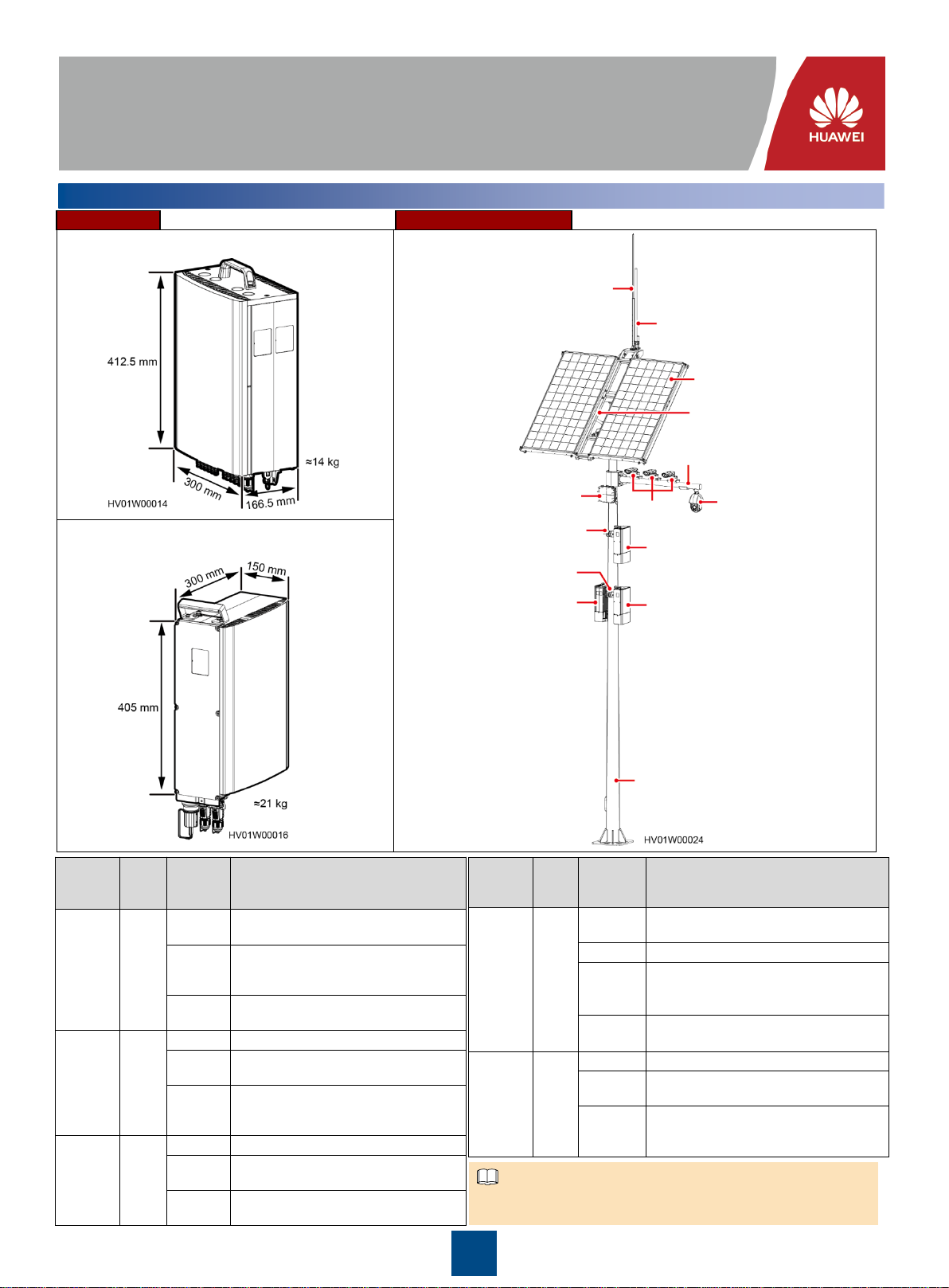
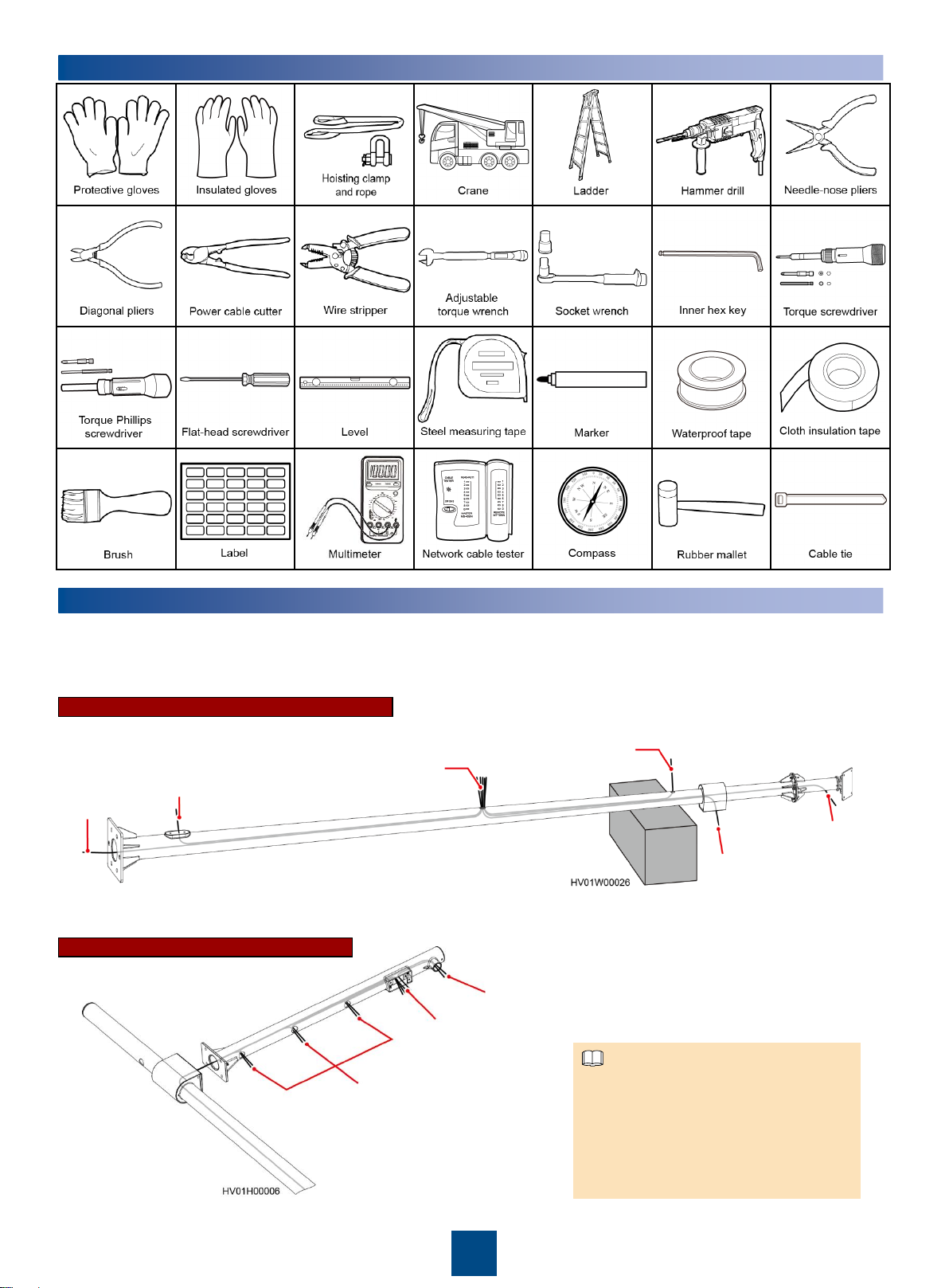
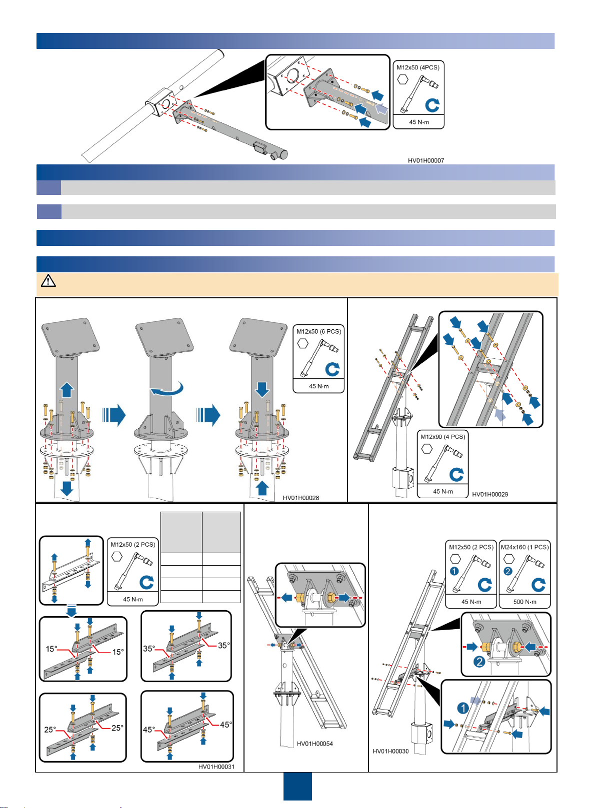
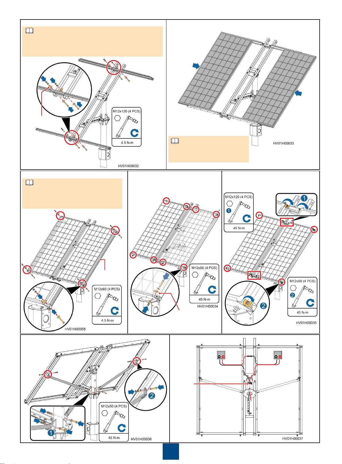
Huawei PowerCube 500 V200R001C10 User manual

1
Issue: 04
Date: 2020-03-30
PowerCube 500 V200R001C10 Quick Guide
(CPS300-N18A1H1)
Copyright © Huawei Technologies Co., Ltd. 2020. All rights reserved.
1Overview
Power module: CPS300-N18A1H1
Lithium battery: CBM20E-N14A1
Appearance Solar Hybrid Scenario
Lithium battery
Lithium battery
Power module
Pole mounting kit
Pole mounting kit
Bullet
cameras
Dome camera
CPE
Lightning rod
Antenna
PV modules
PV module support
Pole
Cantilever
Lithium
Battery
Indicator
Color
Status
Meaning
Run
indicator
(RUN)
Green
Off
The lithium battery has no power input or
is faulty.
Steady on
The lithium battery is powered on.
Blinking
slowly
(0.5 Hz)
The lithium battery is communicating
properly with upstream monitoring
equipment.
Blinking
fast (4 Hz)
The lithium battery fails to communicate
with upstream monitoring equipment.
Alarm
indicator
(ALM)
Red
Off
There is no alarm.
Steady on
The
lithium battery
has generated a fault
alarm and needs to be replaced.
Blinking
slowly
(0.5 Hz)
The
lithium battery has generated a
protection alarm, which can be cleared.
Power
Module
Indicator
Color
Status
Meaning
Run
indicator
Green
Off
The power module has no power input
or is faulty.
Blinking
slowly
(0.5 Hz)
The power module is communicating
properly with upstream monitoring
equipment.
Blinking
fast (4 Hz)
The power module fails to communicate
with upstream monitoring equipment.
Alarm
indicator
Yellow
Off
There is no alarm.
Blinking
slowly
The power module has generated an
alarm, which can be cleared.
Steady
on
The power module has generated an
AC power failure or PV array fault alarm,
which can be cleared.
Fault
indicator
Red
Off
The power module is normal.
Blinking
slowly
The power module has an external fault,
which can be cleared.
Steady
on
The power module has an internal fault,
which cannot be cleared.
NOTE
The three indicators are steady on when the power module is
upgrading. They return to normal status after the upgrade is complete.

2
2Tools
3Routing Cables Through the Pole
1. Place the pole on a wooden case or a similar object.
2. Route a pull wire.
3. Route cables.
Bullet camera signal
cable, power cable,
and ground cable
Dome camera signal cable,
power cable, alarm cable,
and ground cable
Routing Cables Through the Cantilever
Camera
ground cable
Routing Cables Through the Solar Hybrid Pole
Mains AC
cable and
optical fiber
Module
ground cable
Mains AC cable, module
ground cable, optical
fiber, camera cable, CPE
cable, and PV cable
CPE cable
Camera signal
cable, power
cable, and
alarm cable
PV DC input cable
CPE cables can be used only in scenarios
where CPE is adopted.
The cables routed from the pole cable hole
have a length of 1.5 m reserved. The
cables routed from the cantilever cable hole
have a length of 0.5 m reserved.
The object where the pole is placed should
be able to bear a load above 700 kg.
NOTE

3
4Installing a Cantilever
5Installing Cameras and Cables
InstallingCameras
5.1For the camera installation method, see the camera document.
InstallingCamera Cables
5.2For the cable connections at the camera side, see the camera document. Reserve the other ends of cables.
6(Optional) Installing the CPE
For the CPE installation method, see the CPE document.
7Installing PV Modules and Cables (Solar Hybrid Scenario)
In the northern hemisphere, PV modules face due south. In the southern hemisphere, PV modules face due north.
1. Remove the connective kit, adjust the PV module direction based on the PV
module direction principles, and then reinstall the connective kit. 2. Install the PV module support.
3. Adjust the tilt angle of the PV
module support based on the
site latitude.
NOTICE
Site
Latitude
PV
Module
Tilt
Angle
0
–15°
15
°
16
–25°
25
°
26
–30°
35
°
31
–45°
45
°
4. Loosen the bolt at the base
of the PV module support. 5. Install the angle adjustment bracket and
tighten the bolt at the base of the PV module
support.
or
or
or

4
Keep the slots of horizontal beams facing inwards for
installing PV modules.
Partially tighten the bolts so that PV modules can be
adjusted during installation.
6. Install horizontal beams. 7. Install two PV modules.
8. Install raking strut beams for the PV modules. 10.Tighten the bolts at the horizontal beams
and raking strut beams.
11.Install raking struts for the PV modules. 12.Install PV cables.
Adhesive
tape
Spacing shim
Ensure that the openings of the raking
strut beams face outwards.
Partially tighten the bolts to prevent the
PV modules from sliding.
9. Install spacing shims for the
PV modules.
NOTE
NOTE
Ensure that the junction boxes on the
rear of PV modules are positioned
consistently.
NOTE
Spacing shim
Raking
strut beam

5
8Installing an Antenna Fastener and Lightning Rod
Site
Latitude
Lightning Rod
Tilt Angle
0–15°15°
16–25°25°
26–30°35°
31–45°45°
Adjust the tilt angle of the lightning
rod based on the site latitude.
10Installing the Power Module and Lithium Battery
Wear gloves during installation.
Do not place a module with its bottom against the ground.
Never install a module with power on. Ensure that the angle between a module and the line vertical to the ground is within 10 degrees.
The paint on the module exterior should be intact. If paint has flaked off, repaint the area to avoid corrosion.
Installing the Power Module and Lithium Battery on a Pole
10.1
9Installing an Antenna
For the antenna installation method, see the antenna document.
1. Use a positioning
sticker to mark the
installation position
for the pole
mounting kit.
Pole Diameter
(105–140 mm)
Ensure that the arrow on the top of the pole mounting kit points exactly to the middle point on the top of the
positioning sticker.
There are three types of bolts available for installing the pole mounting kit. Choose the appropriate type of
bolts based on the pole diameter.
Bolt
(190 mm)
2. Install the pole mounting kit.
Positioning
sticker Bolt (120 mm) Bolt (160 mm)
Cable hole
Pole Diameter
(140–175 mm) Pole Diameter
(175–210 mm)
NOTE
NOTICE

6
Space Planning InstallationProcedure
(Optional)Installingthe Power Module and Lithium Battery on a Wall
10.2
The wall must be made of reinforced concrete and be able to bear at least 800 N. The wall must not be damaged if subject to a tension of
1.25 kN exerted outwards vertical to the wall.
NOTICE
1. Remove wall mounting kits A and B.
Wall mounting
kit A
Wall mounting
kit B
Unit: mm
3. Install the power module
hanging kit. 4. Install a power module. 5. Install the lithium battery hanging kit.
6. Install a lithium battery.
If two lithium
batteries are required,
install one above the
other. Install the pole
mounting kit after
using a positioning
sticker at the cable
hole in the upper part
of the pole to mark its
installation position.
For the method, see
steps 1 and 2.
7. (Optional) Install the second lithium battery.
The option to
install a lithium
battery
depends on
the scenario.
No lithium
battery is
required in the
grid-only
scenario.
NOTE
NOTE

7
2. Mark mounting holes. 3. Drill holes and install bolts in the holes.
4. Install wall mounting kits B. 5. Install wall mounting kits A.
Level
Marker
Unit: mm
One wall mounting kit A and one wall mounting
kit B are used for each module. Determine the
number of wall mounting kits based on the
number of modules to be installed.
NOTE
Unit: mm
Hammer drill
6. Install the power module
hanging kit. 7. Install a power module onto the wall. 8. Install the lithium battery hanging kit.
The option to install a lithium battery
depends on the scenario. No lithium battery
is required in the grid-only scenario.
NOTE

8
11 Installing the Power Module Antenna
12 Installing Cables
Route inter-device cables through the pole.
InstallingGround Cables for Modules
12.1
Module ground cable
1. Connect ground cables between the power module and lithium batteries. 2. Connect the other end of the module
ground cable to the pole ground bar.
Pole ground bar
Power module Lithium battery Lithium battery
NOTE
If two lithium batteries are
required, install them onto two
adjacent wall hanging kits.
NOTE
9. Install a lithium battery onto the wall. 10.(Optional) Install the second
lithium battery onto the wall.

9
1. Push up the sunshade
until the spring fastener
is stuck gently.
2. Open the maintenance
compartment.
InstallationProcedure
Installing Cables for the Maintenance Compartment
12.2
Cable Hole DiameterRequirements
No.
Cable Hole
Silk Screen Cable Type
Cable Outer
Diameter
1GE RS485 or FE communications
cable
6.8±0.3 mm
2 RS485/FE RS485 or FE communications
cable
3DI Network device power cable
4DO
Dome camera alarm linkage cable
5 12VDC Bullet camera power cable 9.3±0.4 mm
6 24VAC Dome camera power cable
3. Install the dome camera power cable.
The power cable for the
dome camera can only
be connected to the
24VAC port.
4. Install the bullet camera
power cables. 5. Install the NetEco cable.
Network
device
Use waterproof tape to protect
the cable distribution terminal
and put it inside the pole.
NOTE
Dome camera
NOTICE
Bullet camera 1
Bullet camera 2
Bullet camera 3
Cable distribution terminal

10
PV input cables can only be used in scenarios with solar energy.
PV input cables and battery cables are finished cables. You only need to strip the cables and then insert them into the cable terminals.
AC input cables need to be prepared onsite. Multi-core cables must be used; otherwise, waterproof connectors may be exposed to water
leakage.
Before assembling cables with waterproof connectors, ensure that the connections between the cables and terminals are secure and reliable.
Negative (blue)
Positive (red)
PE (green)
N/L2 (blue)
Battery cable terminal
AC input, PV input cable terminal
L/L1 (brown)
Preparing Cable Terminals
12.3
NOTE
6. (Optional) Install the door status sensor.
Dome camera alarm
cable
10.Push down the
sunshade until the
spring fastener is
stuck gently.
8. (Optional) Connect cables to other devices. 9. Close the maintenance compartment door.
NOTE
Before closing the maintenance compartment
door, check that cables are properly installed.
After closing the door, press the left side of the
maintenance compartment door by hand and
tighten the screws.
Cable Type Core Cross-
Sectional Area Cable Outer
Diameter
Battery cable (2-core) 3.3–6 mm2
9.0–14.5 mmPV input cable (2-core) 1.5–4 mm2
AC input cable (3-core) 1.5–4 mm2
Network
device
Smart device
7. (Optional) Install the door status sensor cable and dome camera
alarm linkage cable.

11
Preparing PV Input Cables and Connecting Waterproof Connectors
Scale line
Flat-head
screwdriver
PreparingAC Input Cables and Connecting Waterproof Connectors
(Unit: mm)
Flat-head
screwdriver Scale line
Scale line
Flat-head
screwdriver
Battery Cable (2)
Prepare and install battery cables onsite as required by
referring to Battery Cable (1) or Battery Cable (2).
Flat-head
screwdriver
Battery
cable
Battery Cable (1)

12
Power Module and Lithium Batteries
PV input
AC input
Power module Lithium battery Lithium battery
InstallingPower Cables and SignalCables
12.4
Installingan RJ45 CommunicationsCable for a Lithium Battery
Ensure that caps and waterproof connectors are installed at all idle ports on the modules.
NOTICE
13 Installing Cable Covers
Installinga Cable Cover for the Power Module
13.1

13
14 Erecting the Pole
1. Check whether the pole needs to be repainted. Repaint the damaged area of
the pole, and then use the crane to hoist the pole to the foundation. 2. Secure the pole to the foundation.
16 Power-On Commissioning
15 Verifying the Installation
1. Check the indicators on the power module and lithium batteries. Ensure that the green indicators are blinking slowly and that the
yellow and red indicators are off.
2. If a problem is found, refer to the alarm definitions in the user manual for troubleshooting.
Install a Cable Cover for the Lithium Battery
13.2
1. Check that the mounting kits are securely installed and all screws are tightened.
2. Check that all cables are reliably connected with correct polarity and there is no short circuit.
3. Check whether any screw holes are not installed with screws. If so, install screws at the holes.
4. Check that all idle cable holes in modules are protected with waterproof caps.
Huawei TechnologiesCo., Ltd.
Huawei Industrial Base, Bantian, Longgang
Shenzhen 518129 People's Republic of China
e.huawei.com
Other manuals for PowerCube 500 V200R001C10
1
This manual suits for next models
1
Table of contents
Other Huawei Industrial Electrical manuals
Popular Industrial Electrical manuals by other brands

Murata
Murata GRM155R60G475ME47 Series Reference sheet

Siemens
Siemens MO320 3VA9137-0HA 0 Series operating instructions

Murata
Murata GRM1555C1HR90WA01 Series Reference sheet

PCB Piezotronics
PCB Piezotronics 478B05 Installation and operating manual

Murata
Murata GRM1555C1H7R9DA01 Series Reference sheet

Allen-Bradley
Allen-Bradley 140G-R-EP quick start guide