Huawei OptiX OSN 6800 User manual

HUAWEI TECHNOLOGIES CO., LTD.
OptiX OSN 6800 Intelligent Optical Transport
Platform
Quick Installation Guide (N63B Cabinet)
Issue: 16
Date: 2014-2-14

Huawei Technologies Co., Ltd.
Address: Huawei Industrial Base
Bantian, Longgang
Shenzhen 518129
People's Republic of China
Website: http://www.huawei.com
Email: [email protected]
No part of this document may be reproduced or transmitted in any form or by any means without prior
written consent of Huawei Technologies Co., Ltd.
Copyright © Huawei Technologies Co., Ltd. 2014. All rights reserved.
Trademarks and Permissions
and other Huawei trademarks are trademarks of Huawei Technologies Co., Ltd.
All other trademarks and trade names mentioned in this document are the property of their respective
holders.
Notice
The purchased products, services and features are stipulated by the contract made between Huawei and
the customer. All or part of the products, services and features described in this document may not be
within the purchase scope or the usage scope. Unless otherwise specified in the contract, all statements,
information, and recommendations in this document are provided "AS IS" without warranties, guarantees
or representations of any kind, either express or implied.
The information in this document is subject to change without notice. Every effort has been made in the
preparation of this document to ensure accuracy of the contents, but all statements, information, and
recommendations in this document do not constitute a warranty of any kind, express or implied.

Installation Flow
Precautions
Page 1
Start
Regulation and
Precautions for
Board Handling
Page 2
Tools for
Installation
Page 3
Before You Start
Installing
Subracks
Page 4
to 5
Installing
Boards
Page 6
Setting
Master/Slave
Subracks
Page 7
to 10
Checking the
Battery Jumper
on the SCC
Page
11 to
12
Setting the
Jumpers on the
CRPC
Page
13
Setting the
Jumpers on the
ROP
Page
14
Open
Corrugated Pipe
Page
38
Installing and
Routing
External Fibers
Page
38 to
39
Installing and
Routing Fibers
to a DCM
Frame
Page
40
Installing and
Routing Fibers
Between
Subracks
Page
40
Installing
Subracks and
Boards
Page 4
to 14
Installing
Components
Page
15
Installing and
Routing Cables
Page
16 to
37
Installing and
Routing Fibers
Page
38 to
40
Installing the
Orderwire
Phone
Page
41
Installing the
Digital Video O/E
Conversion
Chassis
Page
42
Checking the
Installation
Page
43 to
44
Setting Up
Optical Paths
Page
45
Engineering
Labels
Page
46 to
47
End
Installing the
DCM Frame
Page
15
Installing the
CRPC/ROP
Frame
Page
15
Cable Holes at
the Top and
Bottom of the
Cabinet
Page
16
Cabinet Power
Cable
Connections
Page
17 to
22
Installing and
Routing Cabinet
Ground and
Power Cables
Page
23 to
26
Installing and
Routing Ground
and Power Cables
to a Subrack
Page
27 to
30
Installing and
Routing Network
Management
Cables
Page
31 to
33
Installing and
Routing Alarm
and Indicator
Cables
Page
34 to
35
Installing and
Routing Clock
Cables
Page
35 to
36
Installing and
Routing Cables to
the CRPC/ROP
Page
37
Installing and
Routing Fibers to a
CRPC Frame
Page
39

1
Precautions
Electrostatic Discharge
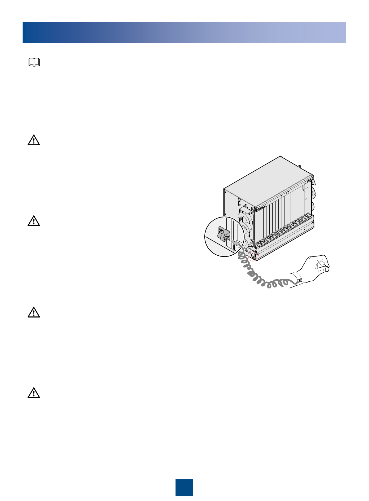
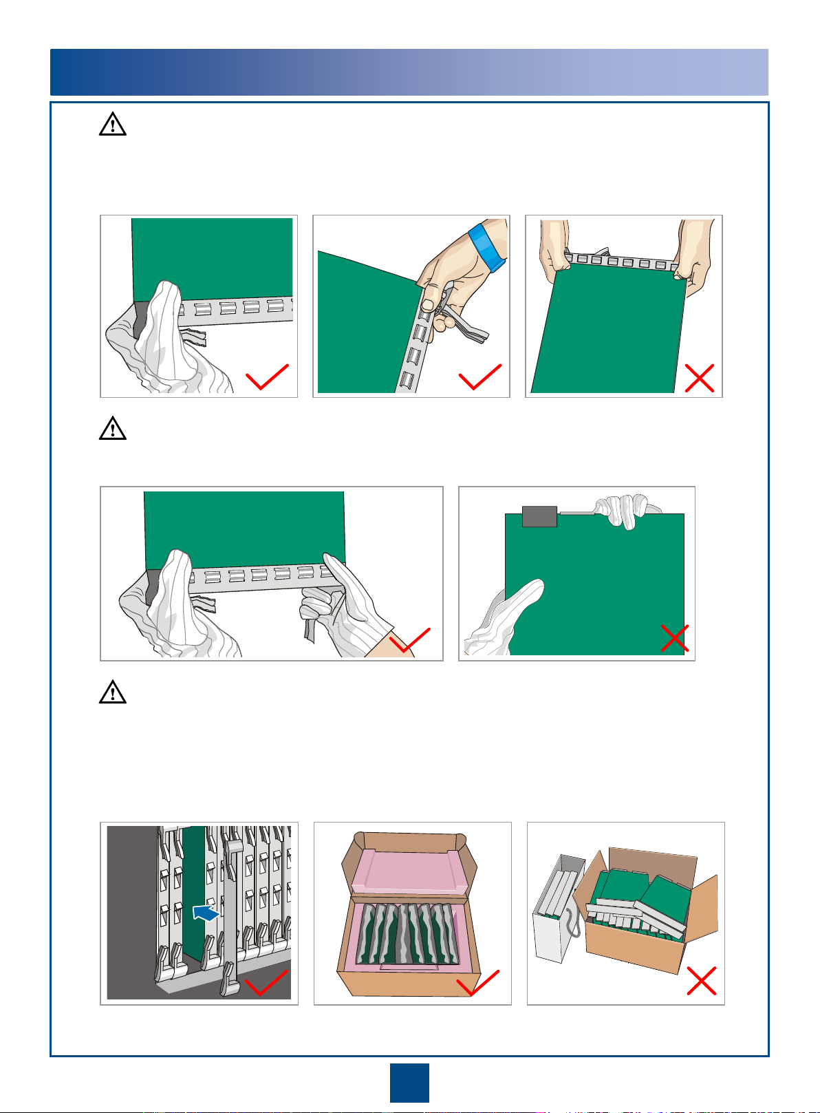
Before touching the device, or holding the boards and IC
chips, wear the anti-static gloves or the anti-static wrist
strap to prevent the electrostatic discharge of the human
body from damaging the sensitive components. Ensure
that the other end of the anti-static wrist strap is well
grounded.
Checking Before Installation
Before starting installation, you should make the equipment room, power supply, ground cable, optical cables, and
other facilities in the equipment ready. When these installation conditions are confirmed, the installation may begin
according to the pre-designed layouts. For detailed requirements and related index, refer to Installation Reference.
Safety Information
When moving the cabinet, wear protective gloves to protect your
hands.
When moving the cabinet, take self-protection measures if the cabinet
inclines.
This document aims to provide simple and distinctive guidelines for hardware installation.
This document does not describe operations for the pre-delivery installation. Instead, this document describers only the
operations for on-site installation.
Bundling cables
The distance between cable ties or fiber holders inside the cabinet should be within 250 mm. (For subscriber cable, the
distance is 200 mm.)
The distance between cable ties for all cables and corrugated pipes outside the cabinet is determined according to the
distance between two horizontal beams. For the cable trough without beams, bundle the cables with the distance not
exceeding 250 mm between cable ties.
CAUTION
CAUTION
CAUTION
CAUTION
NOTE

22
Regulation and Precautions for Board Handing
Do not hold a board without hand protection. Wear an ESD wrist strip or ESD gloves before handling a board.
Insert filler panels into vacant slots on an NE to prevent foreign matters from getting into the NE and system
air ducts from being damaged, which may resulting in faults on the NE.
Boards are fragile and valuable. When handling or placing a board, exercise caution and put it into a
dedicated packing box.
Coherent boards must be packed with original packaging materials during transportation. If the original
packaging materials are lost, contact Huawei.
Holding aboard without hand protectionWearing ESD gloves Wearing an ESD strip
Hold the front panel of a board with both hands.
CAUTION
CAUTION
CAUTION

3
Tool for Installation
Measuring tape
Phillips screwdriver
Flat-head screwdriver
Adjustable wrench Heat gun Segmented blade utility knife
COAX crimping tool
Cable cutter Wire stripper
Power cable crimping tool Network cable testerCoax stripper
RJ45 crimping tool Diagonal pliers
Multimeter
Claw hammer Hammer drill
Socket wrench
Marker

5
19
37
40
60
61
76
81
83
6
20
35
36
22 21
46
47
62
63
77
32
PDU
DCM
4
1
For safety concern, at least two persons are required to install a subrack. One person is to hold the subrack and
the other person to tighten the panel screws.
Place the the subrack onto the column guide rails inside the
cabinet.
Secure the subrack on the cabinet columns with panel screws.
Remove the front door and side doors of the cabinet before routing cables. For details on how to remove the
doors, see the
N63B Cabinet Installation Guide
.
1Installing Subracks(Subracks and Single DCM Frame)
Installing Subracks and Boards
Front
OptiX OSN 6800
Subrack 4
OptiX OSN 6800
Subrack 3
Air deflector
OptiX OSN 6800
Subrack 2
OptiX OSN 6800
Subrack 1
Structural
component
Installation
holes on one
column
DCM frame 2, 3
Subrack 1 5, 6, 19, 20
Subrack 2 21, 22, 35, 36
Air deflector 37, 40
Subrack 3 46, 47, 60, 61
Subrack 4 62, 63, 76, 77
TN11PDU 79, 83
DPD63-4-8
PDU 81, 83
Cabinet
column
Panel screw
NOTE
NOTE

4
37
40
60
61
76
81
83
5
35
36
22 21
46
47
62
63
77
32
6
7
10
12
14
16
PDU
DCM
DCM
DCM
CRPC
CRPC
5
For safety concern, at least two persons are required to install a subrack. One person is to hold the subrack and
the other person to tighten the panel screws.
Install two CRPC boards and multiple DCM frames to the lower subrack.
1 Installing Subracks (Subracks, Two CRPC Boards and Multiple DCM
Frames)
Installing Subracks and Boards
Structural
component
Installation
holes on one
column
DCM frame
2, 3
4, 5
6, 7
CRPC 10, 12
14, 16
Subrack 1 21, 22, 35, 36
Air deflector 37, 40
Subrack 2 46, 47, 60, 61
Subrack 3 62, 63, 76, 77
TN11PDU 79, 83
DPD63-4-8
PDU 81, 83
OptiX OSN 6800
Subrack 3
OptiX OSN 6800
Subrack 2
OptiX OSN 6800
Subrack 1
Front
NOTE
NOTE
Air deflector

Insert the guide strip on the lower side
(without an arrow) of the blank filler
panel to the sliding guide of a vacant
slot, and make sure that the ejector
level is locked to the occlusal notch of
the subrack.
6
2
1
Wear an ESD strap whenever coming into contact with a metal component of the equipment.
2
1
Remove the blank
filler panel. Insert the board. Push the ejector
levers inwards.
Hold the ejector
levers outwards. Remove the
board.
Inserting a board
Removing a board
4
3
12
2 Installing Boards
NOTE
1
12
4
3
Pinch the upper
side (the side with
an arrow) of the
blank filler panel.
Push the upper side (the side
with an arrow) of the blank filler
panel to the subrack. The blank
filler panel is properly installed if
a snap is heard.
1
CAUTION
1. Before installing a board, verify that board connectors have no scratches,
holes, or damage, the backplane has no bent pins, and the plastic cover of the
48 V power connector is not detached. If an abnormality is found, contact
Huawei engineers for help.
2. Handle boards gently to avoid damage to board connectors.

7
3 Setting Master/Slave Subracks
•The J2, J3, J4, J15, J16 jumpers can be set
to enable 32 states that represent decimal
values 0-31.
•The subrack ID is 0 by default. "0" indicates
the master subrack. The other values indicate
slave subracks. The bits from high to low are
J16-J2. As shown in the following figure, the
value represented by the J16 - J2 jumpers is
00001, which is 1 in decimal system. That is,
the subrack ID is 1.
•For details on the principle for configuring the
master and slave subracks, see “Master-
Slave Subrack” in the Product Description.
•Changing the subrack ID may interrupt services.
•The J14, J17, and J18 jumpers must be set as
specified in the figure.
CAUTION
NOTE
Mapping between jumpers binary values and subrack IDs
Subrack ID: 1 - 6
TN11AUX02
J2J3J4
J15J16J17
J14J18
CPU
00
J3 J2
J4
J15
J16
J14
J18
J17
Junper cap
Representing
Jumpers
Representing 1
Representing
00
Representing Representing 0
Representing
0
Representing 0
Representing

8
Subrack ID: 7 - 31
TN11AUX02
3 Setting Master/Slave Subracks

9
TN12AUX
Changing the subrack ID may interrupt services.
CAUTION
•The TN12AUX board has two DIP switches. The value set by each switch can be 0 or 1 (in binary code).
•ID1–ID4 correspond to pins 1–4 on SW2 and ID5–ID8 correspond to pins 1–4 on SW1. ID1–ID5 are valid and ID6–
ID8 are reserved. Keep the ID6-ID8 settings shown in the following figures. From higher bits to lower bits are ID5–ID1,
which can be set to 32 combinations and the default value is 00000. The value 0 indicates the master subrack, and
the other values indicate slave subracks.
•When the DIP switch is toggled to ON, the value of the corresponding bit is set to 0.
NOTE
12 3 4
ON DIP
SW 2
1 2 3 4
ON DIP
SW 1
12 3 4
ON DIP
SW 2
12 3 4
ON DIP
SW 1
(ID 1)
(ID 2)
(ID 3)
(ID 4)
(ID 5)
(ID 6)
(ID 7)
(ID 8)
3 Setting Master/Slave Subracks

10
TN12AUX
Mapping between jumpers binary values and subrack IDs
6
78 9
10
SW1SW1SW1
11
13 14
12 3
45
12
15
SW2SW2SW2
ON
ON
ON
ON
ON
ON
ON
ON
ON
ON
ON
ON
ON
ON
ON
ON
(ID8)
(ID7)
(ID6)
(ID5)
ON
ON
ON
ON
ON
ON
ON
ON
ON
ON
ON
ON
ON
ON
ON
ON
ON
ON
ON
ON ON
ON
ON
ON
ON
ON
ON
ON
ON
ON
ON
ON
ON
ON
ON
ON
ON
ON
ON
ON
ON
ON
ON
ON
ON
ON
ON
ON
ON
ON
ON
ON
ON
ON
ON
ON
ON
ON
ON
ON
ON
ON
ON
ON
ON
ON
ON
ON
ON
ON
ON
ON
ON
ON
ON
ON
ON
ON
ON
ON
ON
ON
ON ON
ON
ON
ON
ON
ON
ON
ON
ON
ON
ON
ON
ON
ON
ON
ON
ON
ON
ON
ON
(ID4)
(ID3)
(ID2)
(ID1)
(ID4)
(ID3)
(ID2)
(ID1)
(ID4)
(ID3)
(ID2)
(ID1)
(ID4)
(ID3)
(ID2)
(ID1)
(ID4)
(ID3)
(ID2)
(ID1)
(ID8)
(ID7)
(ID6)
(ID5)
(ID8)
(ID7)
(ID6)
(ID5)
(ID8)
(ID7)
(ID6)
(ID5)
(ID8)
(ID7)
(ID6)
(ID5)
(ID4)
(ID3)
(ID2)
(ID1)
(ID4)
(ID3)
(ID2)
(ID1)
(ID4)
(ID3)
(ID2)
(ID1)
(ID4)
(ID3)
(ID2)
(ID1)
(ID4)
(ID3)
(ID2)
(ID1)
(ID4)
(ID3)
(ID2)
(ID1)
(ID4)
(ID3)
(ID2)
(ID1)
(ID4)
(ID3)
(ID2)
(ID1)
(ID4)
(ID3)
(ID2)
(ID1)
(ID4)
(ID3)
(ID2)
(ID1)
(ID8)
(ID7)
(ID6)
(ID5)
(ID8)
(ID7)
(ID6)
(ID5)
(ID8)
(ID7)
(ID6)
(ID5)
(ID8)
(ID7)
(ID6)
(ID5)
(ID8)
(ID7)
(ID6)
(ID5)
(ID8)
(ID7)
(ID6)
(ID5)
(ID8)
(ID7)
(ID6)
(ID5)
(ID8)
(ID7)
(ID6)
(ID5)
(ID8)
(ID7)
(ID6)
(ID5)
(ID8)
(ID7)
(ID6)
(ID5)
ON
Subrack
ID:1-15
Subrack
ID Subrack
ID Subrack
ID
SW2SW1SW1
SW2SW1
SW2
28 29 30
31
16 17 18
19 20 21
22 23 24
25 26 27
Err
or
ON
ON
ON
ON ON
ON
ON
ON
ON
ON
ON
ON
ON
ON
ON
ON
ON
ON
ON
ON
ON
ON
ON
ON
ON
ON
ON
ON ON
ON
ON
ON
ON
ON
ON
ON
ON
ON
ON
ON
ON
ON
ON
ON ON
ON
ON
ON
ON
ON
ON
ON
ON
ON
ON
ON
ON
ON
ON
ON
ON
ON
ON
ON
ON
ON
ON
ON ON
ON
ON
ON
ON
ON
ON
ON ON
ON
ON
ON
ON
ON
ON
ON ON
ON
ON
ON
ON
ON
ON
ON
ON
ON
ON
ON
ON
ON
ON
ON
ON
ON
ON
ON
ON
ON
ON
ON ON
ON
ON
ON
ON
ON
ON
ON ON
ON
ON
ON
ON
ON
ON
ON ON
ON
ON
ON
(ID4)
(ID3)
(ID2)
(ID1)
(ID4)
(ID3)
(ID2)
(ID1)
(ID4)
(ID3)
(ID2)
(ID1)
(ID4)
(ID3)
(ID2)
(ID1)
(ID4)
(ID3)
(ID2)
(ID1)
(ID4)
(ID3)
(ID2)
(ID1)
(ID4)
(ID3)
(ID2)
(ID1)
(ID4)
(ID3)
(ID2)
(ID1)
(ID4)
(ID3)
(ID2)
(ID1)
(ID4)
(ID3)
(ID2)
(ID1)
(ID4)
(ID3)
(ID2)
(ID1)
(ID4)
(ID3)
(ID2)
(ID1)
(ID4)
(ID3)
(ID2)
(ID1)
(ID4)
(ID3)
(ID2)
(ID1)
(ID4)
(ID3)
(ID2)
(ID1)
(ID4)
(ID3)
(ID2)
(ID1)
(ID8)
(ID7)
(ID6)
(ID5)
(ID8)
(ID7)
(ID6)
(ID5)
(ID8)
(ID7)
(ID6)
(ID5)
(ID8)
(ID7)
(ID6)
(ID5)
(ID8)
(ID7)
(ID6)
(ID5)
(ID8)
(ID7)
(ID6)
(ID5)
(ID8)
(ID7)
(ID6)
(ID5)
(ID8)
(ID7)
(ID6)
(ID5)
(ID8)
(ID7)
(ID6)
(ID5)
(ID8)
(ID7)
(ID6)
(ID5)
(ID8)
(ID7)
(ID6)
(ID5)
(ID8)
(ID7)
(ID6)
(ID5)
(ID8)
(ID7)
(ID6)
(ID5)
(ID8)
(ID7)
(ID6)
(ID5)
(ID8)
(ID7)
(ID6)
(ID5)
(ID8)
(ID7)
(ID6)
(ID5)
Subrack
ID:16-31 Subrack
ID Subrack
ID Subrack
ID
"EE" indicates that the subrack ID is incorrect or the
subrack ID fails to be obtained.
3 Setting Master/Slave Subracks

11
Make sure that the jumper settings are set as shown in the following figure prior to using an SCC
board. When a battery is required, place a jumper cap over pin 3 and pin 2. When the power
supplied by the battery is not required, place a jumper cap over pin 2 and pin 1.
4 Checking the Battery Jumper on the SCC
CAUTION
TN11SCC
CPU
Battery Jumper
CF
Card
Battery Jumper
J11
J11
J11
Battery is
used
Battery is
not used

12
Make sure that the jumper settings are set as shown in the following figure prior to using an SCC board. When a
battery is required, place a jumper cap over pin 3 and pin 2. When the power supplied by the battery is not required,
place a jumper cap over pin 2 and pin 1.
4 Checking the Battery Jumper on the SCC
CAUTION
TN51SCC
Battery Jumper
Battery is used Battery is not used
J1 1
3
2
J1 1
3
2
CF
Card
Battery Jumper
J1 21
3
Battery Jumper
Battery
is used
Battery
is not
used J1
1
3
2
J1
1
3
2
Battery Jumper
C
F卡
J1
CF
Card
32
1
TN52SCC

13
5 Setting the Jumpers on the CRPC
There are two groups of jumpers on the CRPC boards. The two groups are identified as J3 and J4.
Jumpers 9 to 10 in J3 and 1 to 6 in J4 are used for internal identification on the board.
To ensure the normal operation of the board, follow the requirements below to set the jumpers.
Do not connect jumpers 1 to 2 in J3.
Do not connect jumpers 3 to 4 in J3.
Do not connect jumpers 5 to 6 in J3.
Do not connect jumpers 7 to 8 in J3.
Do not connect jumpers 9 to 10 in J3. (Non-extended slot numbering mode)
Connect jumpers 9 to 10 in J3. (Extended slot numbering mode)
Connect jumpers 1 to 2 in J4.
Connect jumpers 3 to 4 in J4.
Connect jumpers 5 to 6 in J4.
Jumpers 7-8 and 9-10 in J4 are used to set the slot of the CRPC board. The following are jumper
setting regulations in the non-extended slot numbering mode:
When jumpers 7-8 and 9-10 in J4 are not connected, the board slot is IU28.
When jumpers 7-8 in J4 are connected and jumpers 9-10 are not connected, the board slot is IU29.
When jumpers 7-8 in J4 are not connected and jumpers 9-10 are connected, the board slot is IU30.
When jumpers 7-8 and 9-10 in J4 are connected, the board slot is IU31.
The following are jumper setting regulations in the extended slot numbering mode:
When jumpers 7-8 and 9-10 in J4 are not connected, the board slot is IU120.
When jumpers 7-8 in J4 are connected and jumpers 9-10 are not connected, the board slot is IU121.
When jumpers 7-8 in J4 are not connected and jumpers 9-10 are connected, the board slot is IU122.
When jumpers 7-8 and 9-10 in J4 are connected, the board slot is IU123.
NOTE
1
2
9
10
10
1
2
9
J4 J3
CPU
J3J4
CRPC

14
6 Setting the Jumpers on the ROP
There are two groups of jumpers on the ROP boards. The two groups are identified as J3 and J4.
Jumpers 9 to 10 in J3 and 1 to 6 in J4 are used for internal identification on the board.
To ensure the normal operation of the board, follow the requirements below to set the jumpers.
•Never cap jumpers 1 to 2 in group J3.
•Never cap jumpers 3 to 4 in group J3.
•Never cap jumpers 5 to 6 in group J3.
•Never cap jumpers 7 to 8 in group J3.
•Never cap jumpers 9 to 10 in group J3 (in non-extended slot numbering mode).
•Always cap jumpers 9 to 10 in group J3 (in extended slot numbering mode).
•Always cap jumpers 1 to 2 in group J4.
•Always cap jumpers 3 to 4 in group J4.
•Never cap jumpers 5 to 6 in group J4.
Jumpers 7-8 and 9-10 in group J4 are used to specify the logical slot for the ROP board.
When setting jumpers 7-8 and 9-10 in group J4 in non-extended slot numbering mode, follow the instructions below:
•When jumpers 7-8 and 9-10 in group J4 are not capped, the logical slot for the ROP board is IU28.
•When jumpers 7-8 in group J4 are capped and jumpers 9-10 are not capped, the logical slot for the ROP board is IU29.
•When jumpers 7-8 in group J4 are not capped and jumpers 9-10 are capped, the logical slot for the ROP board is IU30.
•When jumpers 7-8 and 9-10 in group J4 are capped, the logical slot for the ROP board is IU31.
When setting jumpers 7-8 and 9-10 in group J4 in the extended slot numbering mode, follow the instructions below:
•When jumpers 7-8 and 9-10 in group J4 are not capped, the logical slot for the ROP board is IU124.
•When jumpers 7-8 in group J4 are capped and jumpers 9-10 are not capped, the logical slot for the ROP board is IU125.
•When jumpers 7-8 in group J4 are not capped and jumpers 9-10 are capped, the logical slot for the ROP board is IU126.
•When jumpers 7-8 and 9-10 in group J4 are capped, the logical slot for the ROP board is IU127.
NOTE
1
2
9
10
10
1
2
9
J4 J3
CPU
J3J4
ROP

15
Installing Components
1Installing the DCM Frame
2 Installing the CRPC/ROP Frame
Each DCM requires four screws. If only one DCM is
required, install it to the left side of the DCM frame
to facilitate distribution of optical fibers on the left.
31
2
The CRPC frame is installed in the location ordinarily intended for the lower subrack.
It is recommended that 2U-height (89 mm) space be reserved on the top of the CRPC/ROP frame for
heat dissipation. Do not block the air inlets or outlets of the frame.
Secure the mounting ear on
each side of the frame by
tightening screws.
Secure the frame on the
columns of the cabinet by
tightening screws through the
holes on the mounting ears.
Panel screws
Panel screws
ROP frame ROP board CRPC frame CRPC board Mounting ear
DCM
frame
DCM
Mounting
ear
Screw
Phillips screwdriver
NOTE
NOTE

16
Installing and Routing Cables
1 Cable Holes at the Top and Bottom of the Cabinet
Cable Holes at the Bottom of the Cabinet
b
Route optical fibers and cables into a cabinet through the cable holes at the top or bottom of the cabinet.
a
Cable holeCable hole
NOTE
Cable hole
Power cable hole
Cable hole
Cable holeCable hole
Cable Holes at the Top of Cabinet

17
2 Cabinet Power Cable Connections (TN11PDU)
Power cable connections vary depending on the power sources in the equipment room. When the power source
supplies one input of 63 A, TN11PDU is used to interface four main/backup power inputs.
Power Cable Connections to the Cabinet
a
A-NEG1(-)
A-NEG2(-) B-NEG1(-)
B-NEG2(-)
A-RTN1(+)
A-RTN2(+) B-RTN1(+)
B-RTN2(+)
PGND
-48 V-48 V
0 V0 V-48 V-48 V
0 V0 V
Power source in the
equipment room
Power source in the
equipment room
Subrack 2
Subrack 1
Cabinet power cables
Adjustable wrench
Flat-head screwdriver
Ground cables
Subrack 3
Ground bar
NOTE
Subrack 4
Table of contents
Popular Network Accessories manuals by other brands

Cisco
Cisco Catalyst 9600 Series Installation note

Paradyne
Paradyne 8820 installation instructions

Paradyne
Paradyne 7610 user guide

Black Box
Black Box IC160A Specifications

Net to Net Technologies
Net to Net Technologies UIM-1000 installation instructions

SamKnows
SamKnows whitebox version 1 installation instructions