Clearfield FieldShield YOURx-Terminal User manual

FieldShield YOURx-Terminal
Installation Manual ______________________________________________________
Manual 018994 REV A - July 2017

Direct: 763.476.6866 • National: 800.422.2537 • www.SeeCleareld.com • [email protected]
2
FieldShield YOURx-Terminal
Installation Manual _________________________________________________________
Manual 018994 REV A - July 2017
Table of Contents
Parts List 3
Recommended Tools 4
Working in the YourX Terminal 6
Opening the Cover 6
DropTerminalCongurations 7
Port Designations 8
MPO Wiring Diagrams 9
Optical Components 13
SplitterCongurations 13
Buried Deployment Methods 15
Mounting Application 15
Pedestal Mounting 15
Vault Installation 16
Site Preparation 16
Pole/Wall Mounting 18
Cover Mount Bracket 19
Strand Mount 20
Preparing Terminal Ports 21
Installing FlexPorts in the Field 21
Plugs 22
Preparing Microduct to Connect to Terminal 22
Installation of Fiber 23
Slack Storage 27
Using a GasBlock Coupler (greater than 10 feet 27
Using a Slack Storage Reel (less than 10 feet) 28
Closing the YOURx Terminal 28
Connector Cleaning Procedure 29
Standard Warranty 32
Proprietary Notice 33
Technical Support 33

3
FieldShield YOURx-Terminal
__________________________________________________________ Installation Manual
Direct: 763.476.6866 • National: 800.422.2537 • www.SeeCleareld.com • [email protected]
Manual 018994 REV A - July 2017
2
6
3
7
9
1
4
5
6
8
1. Base (FlexPort Sealing Tabs marked with a silver “x” inside the terminal)
2. Cover
3. Gasket
4. Clips (8 installed on base)
5. FlexCartridge
6. FlexPort ½ (half) Cartridge
7. Plugs (available 10mm and 14mm)
8. Designation Card
9. FlexCartridge Cover
10. Base Mounting Bracket*
11. Cover Mounting Bracket*
12. Aerial Strand Bracket*
*Ordered Seperately (not included with terminal)
10
12
11
Parts List
Direct: 763.476.6866 • National: 800.422.2537 • www.SeeCleareld.com • [email protected]
4
FieldShield YOURx-Terminal
Installation Manual _________________________________________________________
Manual 018994 REV A - July 2017
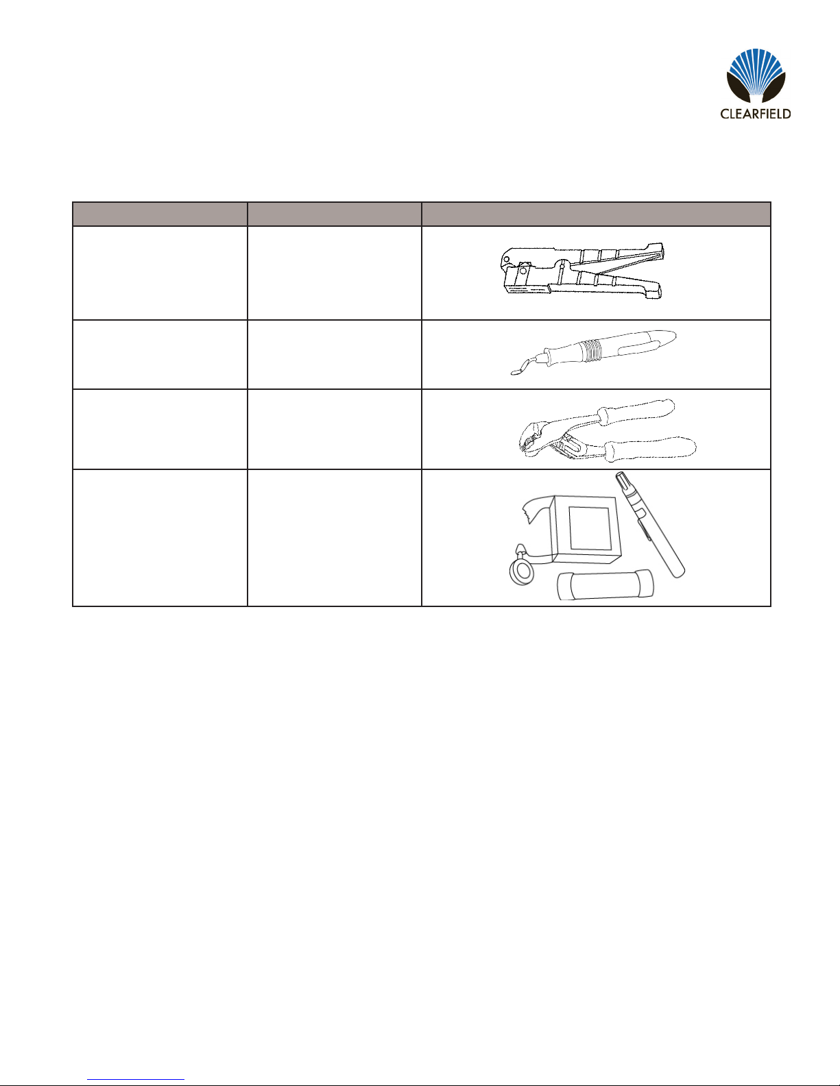
Find No. Tool Image
001 Rotary Cutter
002 Deburring Tool
003 Pliers
004 Optical End Face
Cleaning kit
Recommended Tools
5
FieldShield YOURx-Terminal
__________________________________________________________ Installation Manual
Direct: 763.476.6866 • National: 800.422.2537 • www.SeeCleareld.com • [email protected]
Manual 018994 REV A - July 2017
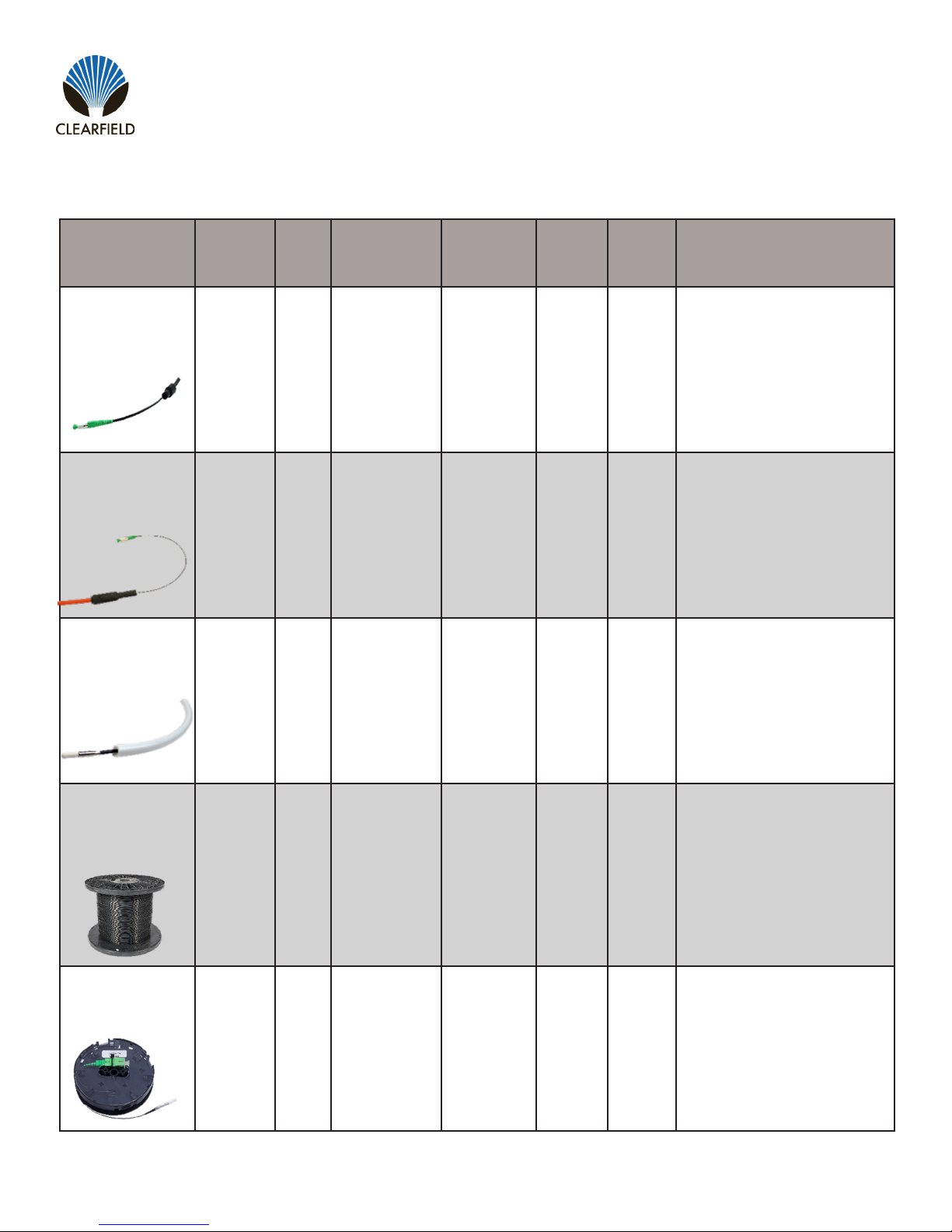
Product
Name
Cable
Jacket UV Temperature FieldShield
Connector
Jacket
Color
Can be
stapled
Best
Application
FieldShield
FLATdrop
Outdoor Yes -40° to 176°F No Black Yes
For use when fast installation
and low up-front cost is most
desired feature.
FieldShield
D-ROP
Outdoor Yes -40° to 176°F Yes Black/
Orange Yes
For use when a single pass
and restorable solution at a
competitive price is ideal.
FieldShield
FLEXdrop
Indoor
(Plenum)/
Outdoor
Yes -40° to 176°F Yes Black/
White Yes
For use when a premium
product that has maximum
workability, exibility and
restorability is desired.
FieldShield
(Classic)
Outdoor
in Duct
Yes in
Duct -40° to 176°F Yes Black Yes
For use when the distance
from the access point to the
SFU/MDU is longer than
normal and a more rigid solu-
tion is required to maintain
restorability for drops longer
than 300 feet.
FieldShield
StrongFiber
Indoor/
Outdoor
in Duct
Yes in
Duct -40° to 176°F Yes Black Yes in
Duct
For use when a reusable
pathway is needed and
maximum slack storage is
desirable.
DROP CABLE OPTIONS

Direct: 763.476.6866 • National: 800.422.2537 • www.SeeCleareld.com • [email protected]
6
FieldShield YOURx-Terminal
Installation Manual _________________________________________________________
Manual 018994 REV A - July 2017
Working in the YourX Terminal
This instruction manual describes the recommended installation of the YourX multi-port terminal utilizing various ber drop
applications.
Opening the Cover
Pull the 8 tabs down from cover toward base. (Figure 1)
The lid may be difcult to remove due to gasket sealing.
Figure 1
DO NOT use a sharp item (snips, screwdriver, etc.) to remove.
Utilize a stiff at piece of plastic, like a wedge, to help break the seal.
Using the sharp items may damage the gasket.
!
IMPORTANT
7
FieldShield YOURx-Terminal
__________________________________________________________ Installation Manual
Direct: 763.476.6866 • National: 800.422.2537 • www.SeeCleareld.com • [email protected]
Manual 018994 REV A - July 2017
• “Drop only” where there is a choice of one 14mm or one 10M port used for feed (MPO input) and designated
number of ports for distribution (Figure 1).
• “Drop and Express” congured terminals will utilize both “A and B” ports for feed (MPO input) to terminal with
expressing (MPO output) the un-used bers to the next terminal in line (Figure 2).
DropTerminalCongurations
Figure 1
NOTE: These are “standard” congurations, your terminal may be unique to your environment
REMEMBER: SC/LC/MPO ports on FlexCartridge are opposite of labeling in base to minimize ber crossover
Figure 2
DROP ONLY example DROP and EXPRESS example
NOTE: If terminal is being utilized with splitters, the feed may be fed through 10MM Port of choice for termination
Cable Feed/Express Port Types
14MM: Microduct with pushable MPO
10MM: FlatMPO
10MM: Pushable 1F for Splitter feed
Direct: 763.476.6866 • National: 800.422.2537 • www.SeeCleareld.com • [email protected]
8
FieldShield YOURx-Terminal
Installation Manual _________________________________________________________
Manual 018994 REV A - July 2017
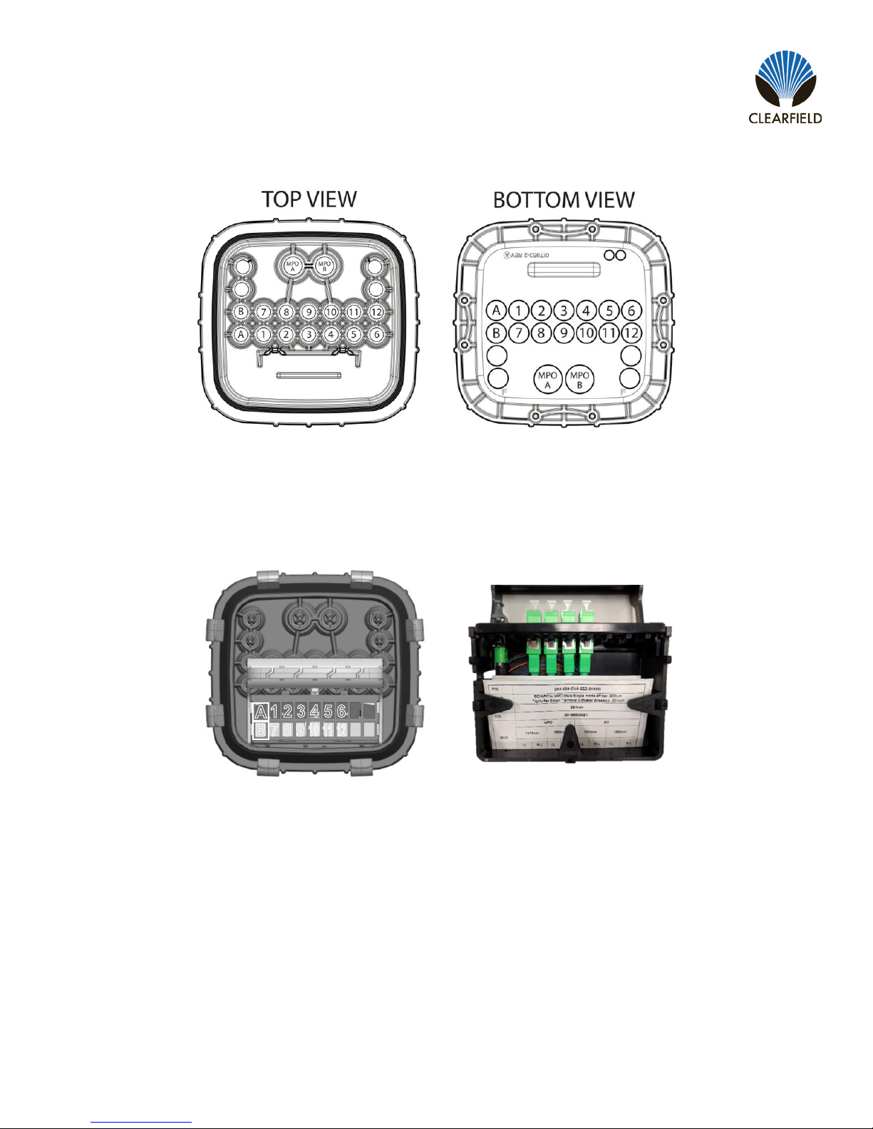
Port Designations
Ports A and B: 14MM
Ports 1 thru 16: 10 MM Microduct
NOTE: Pushable MPO’s enter through the 14MM ports. When a third MPO is needed, you will utilize a “FLATMPO” cable
with a hardened connector and enter through a 10MM port
FlexCartridge Designations
1 2 3 4 5 6
7 8 9
10
11
12
A
B
Port counts differ, depending on terminal designation
MPO Ports
A - Fiber “IN” (feed)
B - Fiber “OUT” (express
Distribution Ports 1-12
SC, LC or MPO connectors
Test record found behind
removeable cover
9
FieldShield YOURx-Terminal
__________________________________________________________ Installation Manual
Direct: 763.476.6866 • National: 800.422.2537 • www.SeeCleareld.com • [email protected]
Manual 018994 REV A - July 2017
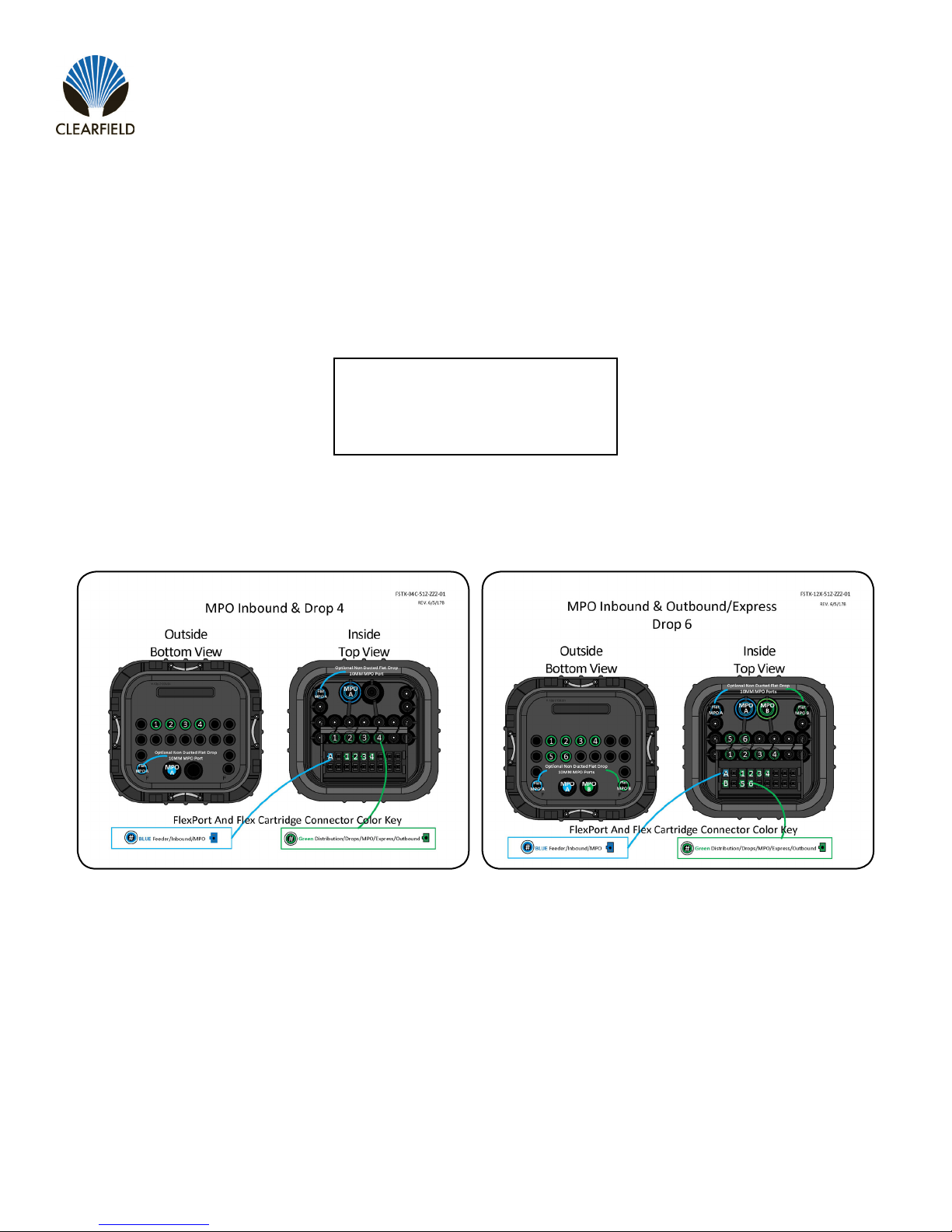
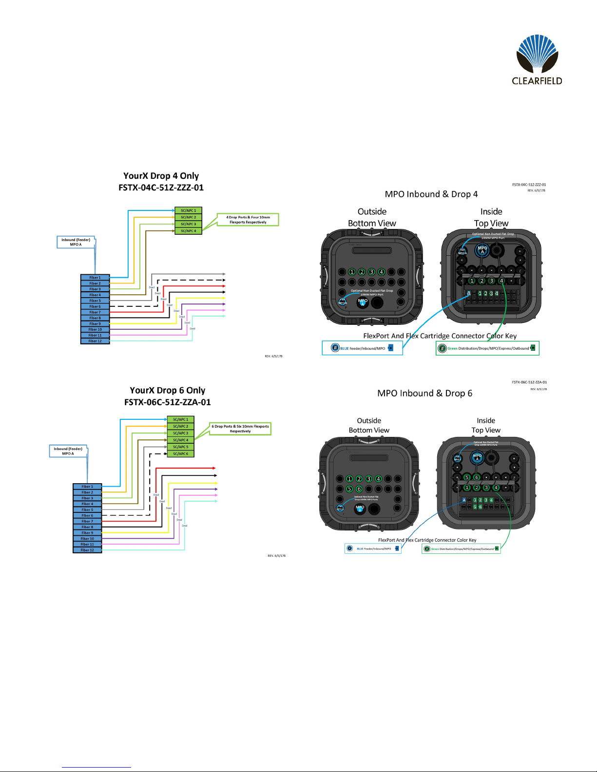
MPO Wiring Diagrams
MPO (Labeled “A” and/or “B”) ber designation
Congurations consist of “Drop Only” (Figure 1)
terminals as well as “Drop and Express” terminals uti-
lizing pushable single ber, MPO or FlatMPO cables.
Drop Only Terminals will utilize 1 (one) 14MM or 1
(one) 10MM port, based on cable feed choice. When
using FlatMPO, the 10MM port located left of “A”
14MM, is recommended.
Drop and Express” will utilize the “B” port for
expressing bers via 14mm duct or the 10MM port to
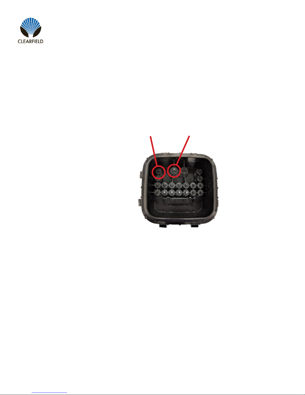
the right of “B”. Figure 1
Example of a 4-port Drop
only terminal with a 14MM
feed FlexPort
Each FLEXport installed from
the factory are marked with
silver X.
“A” 10mm “A” 14mm
Direct: 763.476.6866 • National: 800.422.2537 • www.SeeCleareld.com • [email protected]
10
FieldShield YOURx-Terminal
Installation Manual _________________________________________________________
Manual 018994 REV A - July 2017
MPO Inbound & DROP
11
FieldShield YOURx-Terminal
__________________________________________________________ Installation Manual
Direct: 763.476.6866 • National: 800.422.2537 • www.SeeCleareld.com • [email protected]
Manual 018994 REV A - July 2017
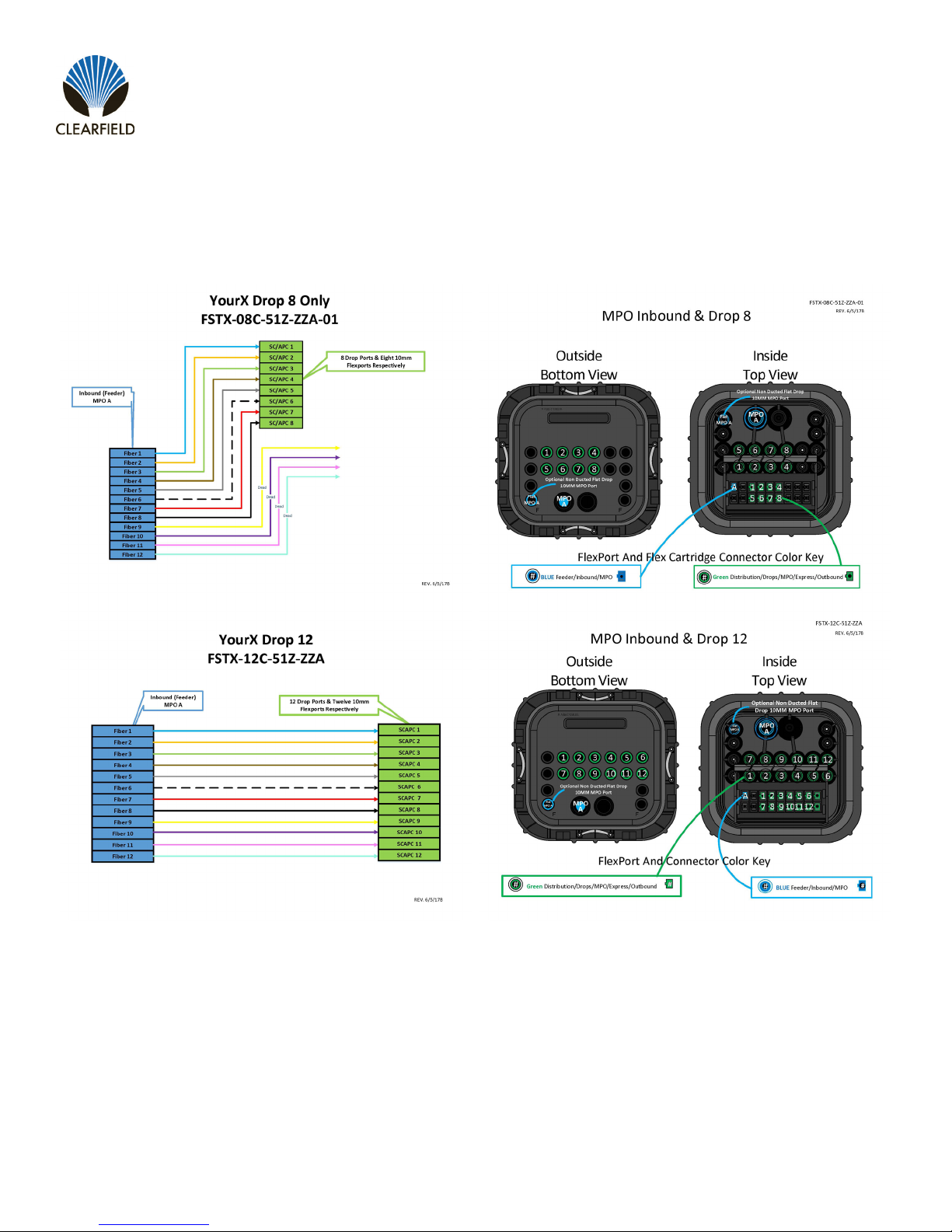
MPO Inbound & DROP
(continued)
NOTE: These are “standard” congurations. Your terminal may be unique to your application.
REMEMBER: SC/APC Flexports, are labeled opposite of FLEXport on terminal base
Direct: 763.476.6866 • National: 800.422.2537 • www.SeeCleareld.com • [email protected]
12
FieldShield YOURx-Terminal
Installation Manual _________________________________________________________
Manual 018994 REV A - July 2017
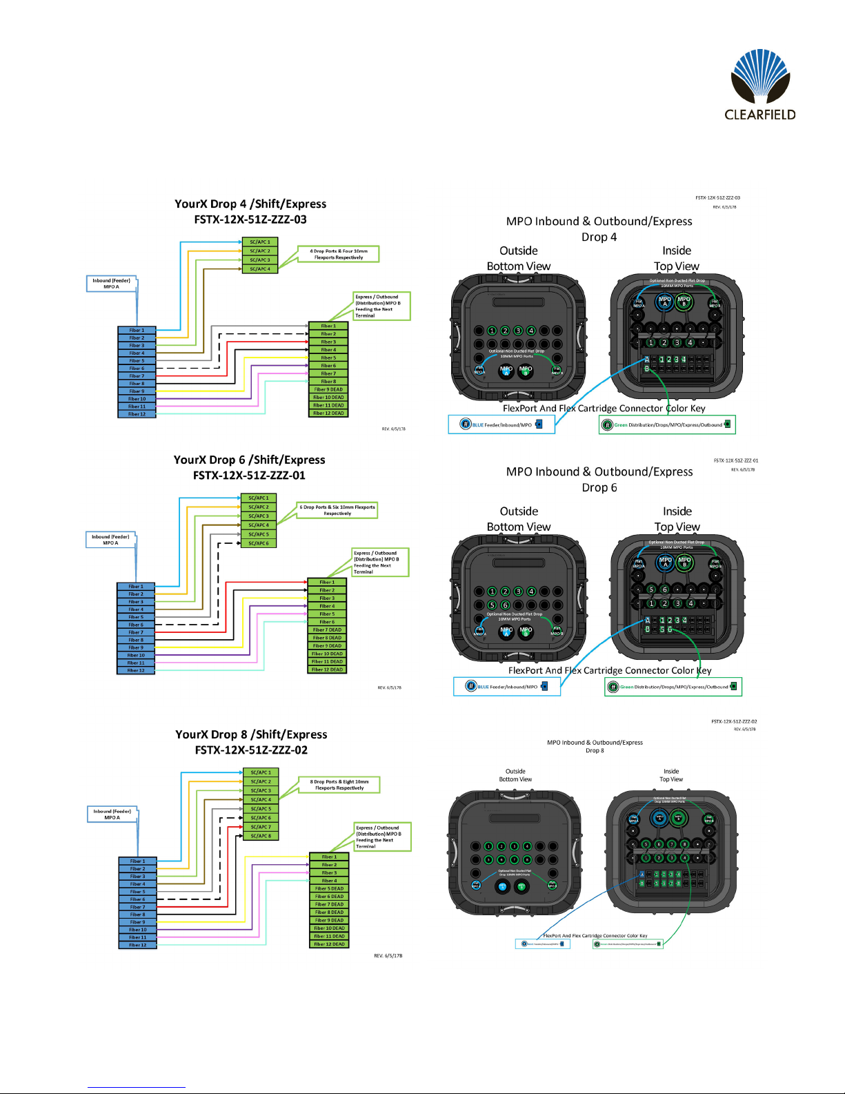
MPO Inbound & outbound/express with DROP
NOTE: These are “standard” congurations. Your terminal may be unique to your application.
13
FieldShield YOURx-Terminal
__________________________________________________________ Installation Manual
Direct: 763.476.6866 • National: 800.422.2537 • www.SeeCleareld.com • [email protected]
Manual 018994 REV A - July 2017
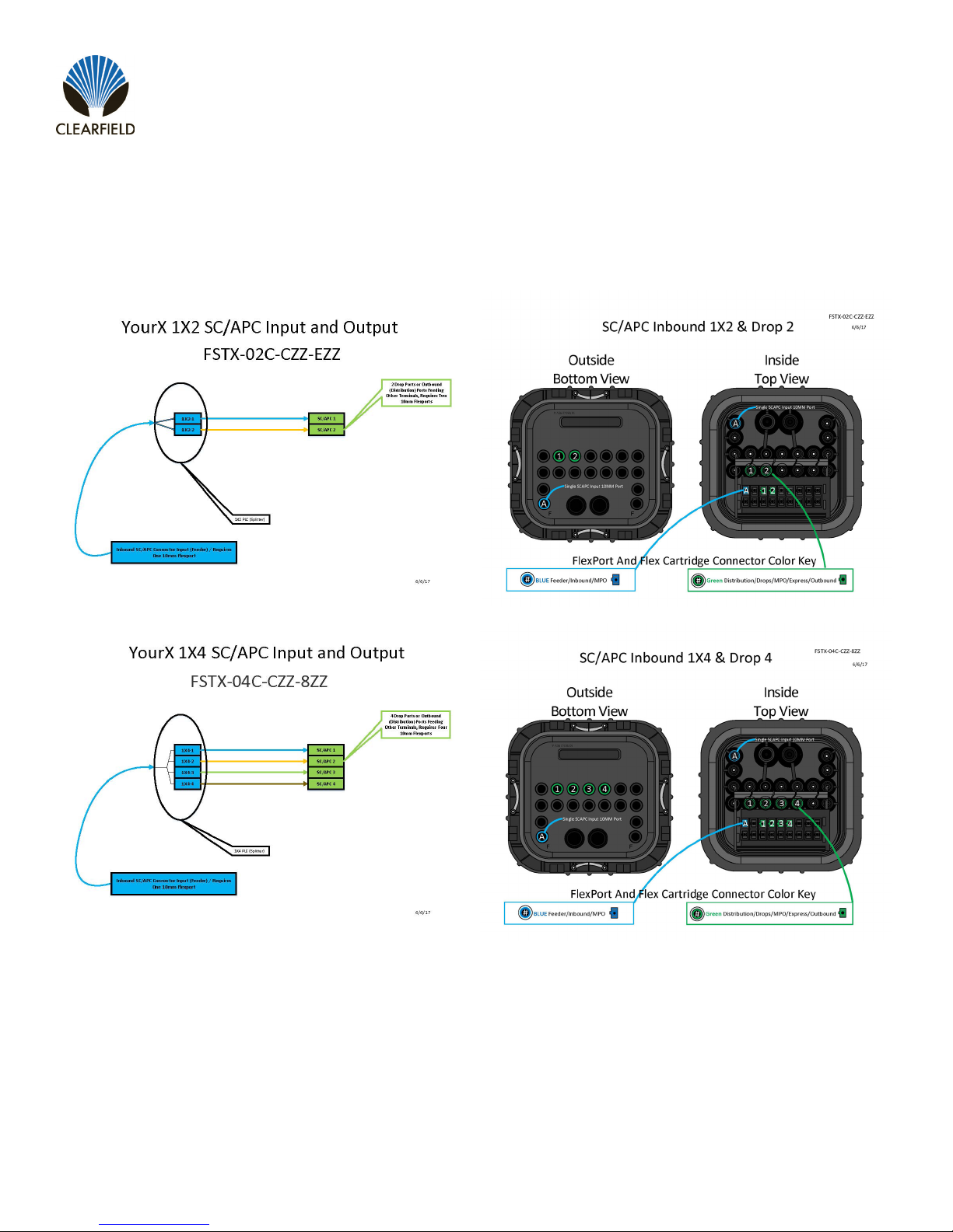
Optical Components
SplitterCongurations

Direct: 763.476.6866 • National: 800.422.2537 • www.SeeCleareld.com • [email protected]
14
FieldShield YOURx-Terminal
Installation Manual _________________________________________________________
Manual 018994 REV A - July 2017

15
FieldShield YOURx-Terminal
__________________________________________________________ Installation Manual
Direct: 763.476.6866 • National: 800.422.2537 • www.SeeCleareld.com • [email protected]
Manual 018994 REV A - July 2017
Mounting Application
Pedestal Mounting
The YourX terminal can be mounted for various applications. These directions are for basic installation in the outside plant.
Your application may vary from our basic design installation method.
Terminal base is mounted,
remove lid for access.
Terminal lid is mounted,
loosen thumbscrew to
free terminal from bracket,
remove lid for access.
NOTE: The YourX terminal is capable of tting into as small as an 8 X 8 pedestal but due to room restrictions we
recommend a minimum of 10 X 10.
Buried Deployment Methods
YOURx Terminal can be placed in:
Pedestals
(min 10x10)
Vaults (w/o brackets)

Direct: 763.476.6866 • National: 800.422.2537 • www.SeeCleareld.com • [email protected]
16
FieldShield YOURx-Terminal
Installation Manual _________________________________________________________
Manual 018994 REV A - July 2017
Figure 1
Step 1: Excavation
Plan excavation approximately twelve
to sixteen inches (12” - 16”) longer/
wider and six to eight inches (6” - 8”)
deeper than the actual dimensions of
the vault being installed. (Figure 1)
Site Preparation
Ensure that national – local electrical and building codes, OSHA and company safety work rules are observed and provi-
sions made for street ags, barricades and cones. Secure permits as required by city and company.
Figure 3Figure 2
Step 2:Drainage Base
Pour gravel base to a depth of three to
ve inches at (3” - 5”) the base of the
excavation. (Figure 2)
Note: Base material should be crushed
rock 3/4” and smaller, and not “river
rock” or “round stone.”
Step 3:Install Vault
Guide microduct through opening and
lower vault into excavation on top of
base material and adjust height to
grade. (Figure 3)
Vault Installation
WARNING: Buried Telecommunications Cables. Make sure to call 811 a few days before digging.
Calling 811 will route to the local one-call center and ensure that utilities in the area of installation
will be located and marked.
!
IMPORTANT

17
FieldShield YOURx-Terminal
__________________________________________________________ Installation Manual
Direct: 763.476.6866 • National: 800.422.2537 • www.SeeCleareld.com • [email protected]
Manual 018994 REV A - July 2017
Figure 4 Figure 6Figure 5
Step4:Backll
Use soil to backll between the vault
and the excavation wall, tamping down
to compact soil. (Figure 4)
Step 5:Route Duct
Deterimine desired length of all ducts
entering the terminal. (Figure 5)
Note: Multiple ducts should be bound
together with vinyl tape for easier
manipulation.
Step 6:Prepare Duct
Use a rotary cutting tool to all ducts to
equal length. Strip back outer sheath
and tone wire six inches (6”) or
amount needed to terminate to bond/
locating bar. Use de-burring tool to
chamfer end of duct. (Figure 6)
Figure 7 Figure 8
Step 7:Prepare Ports
Remove tabs from desired terminal
FlexPorts. De-burr FlexPort with snips,
knife or de-burring tool to remove
rough edges. MUST de-burr entirely
for FlatMPO bullet to t through port.
(Figure 7)
Note: Tab removal may require pliers
Step 8:Seat Duct
Feed pull string from the underside of
the terminal through port and seat duct
fully into the coupler. (Figure 8)
Step 9:Secure Pull String
Tie off pull string to FlexCartridge to
prevent it from migrating back into the
microduct.
Note: Ports loaded with exports are marked in silver.

Direct: 763.476.6866 • National: 800.422.2537 • www.SeeCleareld.com • [email protected]
18
FieldShield YOURx-Terminal
Installation Manual _________________________________________________________
Manual 018994 REV A - July 2017
Pole/Wall Mounting
Utilizing the horeshoe bracket, mount bracket to surface (hardware not included) mount YourX terminal to bracket using the
provided hardware. (3 mounting locations – 4 provided screws) (Figure 1)
Figure 1
(4) mounting screws provided
Terminal base is mounted
to bracket utilizing provided
hardware.
Microduct will be cut to desired length for proper storage,
following local practice.
Be sure to adhere to bend radius of microduct and at drop.
FOLLOW DIRECTIONS FOR:
Installing Microduct and Flat Drop into Terminal
Installing ber and managing inside terminal
I.B.Y.C

19
FieldShield YOURx-Terminal
__________________________________________________________ Installation Manual
Direct: 763.476.6866 • National: 800.422.2537 • www.SeeCleareld.com • [email protected]
Manual 018994 REV A - July 2017
Cover Mount Bracket
Two piece mounting bracket. The bracket is attached to the top of the cover where it can be removed from mounting
location. Allowing technician to move terminal along with microduct for mounting application needs.
Figure 1
Figure 2
Figure 3
Figure 4
Using the 2 screws provided, attach base (Figure 2) to cover of YourX terminal (Figure 3)
Mount the bracket (Figure 1) to the desired location (hardware not included).
Place forks of mounting bracket under wing nut and nger tighten. (Figure 4)

Direct: 763.476.6866 • National: 800.422.2537 • www.SeeCleareld.com • [email protected]
20
FieldShield YOURx-Terminal
Installation Manual _________________________________________________________
Manual 018994 REV A - July 2017
Strand Mount
1. Attach lanyard using provided screw, to location identied in (Figure 1).
2. Attach opposite end to location in (Figure 2).
3. Using provided hardware attach base to bracket like shown (Figure 3).
4. Attach to strand using provided bug nuts. Facing FlexPorts toward
serving pole.
5. Dress duct from pole attachment to terminal, cut duct to length.
6. FOLLOW DIRECTIONS FOR:
1. Installing Duct Into Terminal
2. Installing ber Into Terminal
3. I.B.Y.C! (Inscpect Before You Connect!)
Figure 1 Figure 2 Figure 3
Other manuals for FieldShield YOURx-Terminal
1
Table of contents
Other Clearfield Network Accessories manuals


