Huawei OptiXRTN 980L User manual

HUAWEI TECHNOLOGIES CO., LTD.
OptiX RTN 980L Radio Transmission System V100
Quick Installation Guide (Integrated LH)
Issue: 02
Date: 2019-04-30

No part of this document may be reproduced or transmitted in any form or by any means without prior
written consent of Huawei Technologies Co., Ltd.
Copyright © Huawei Technologies Co., Ltd. 2019. All rights reserved.
Trademarks and Permissions
and other Huawei trademarks are trademarks of Huawei Technologies Co., Ltd.
All other trademarks and trade names mentioned in this document are the property of their respective
holders.
Notice
The purchased products, services and features are stipulated by the contract made between Huawei and
the customer. All or part of the products, services and features described in this document may not be
within the purchase scope or the usage scope. Unless otherwise specified in the contract, all statements,
information, and recommendations in this document are provided "AS IS" without warranties, guarantees
or representations of any kind, either express or implied.
The information in this document is subject to change without notice. Every effort has been made in the
preparation of this document to ensure accuracy of the contents, but all statements, information, and
recommendations in this document do not constitute a warranty of any kind, express or implied.
Huawei Technologies Co., Ltd.
Address: Huawei Industrial Base
Bantian, Longgang
Shenzhen 518129
People's Republic of China
Website: http://www.huawei.com
Email: [email protected]

2
Contents
Installation Tools
Precautions
Equipment Components
Cabinet
1BU
2
Cables
IDU
RFU
3
5
4
Installing XPIC Cables
Installing IDU Cables
1
3
2Installing IF Cables
Installing Ethernet Service Cables
Installation Process
Installing Orderwire Phone Cables
11 Installing External Alarm Cables
10
7
Installing E1 Cables
8Installing Asynchronous and Synchronous Data Cables
9
Installing STM-1e Cables
Installing NM Cables
Installing External Clock Cables
5
6
Installing Fibers
4
Purchase List (North America)
Commissioning Process
Laying out Cabinet Cables
Installing Cabinet Cables
1
3
2Installing Power Cables
Installing Ground Cables
11
4
13
13
14
14
16
15
23
26
23
26
17
33
32
29
30
31
28
28
27
10
18
19
19
22
21

3
Contents
Installing a Dehydrator
Dehydrator Connection Diagram
1Dehydrator Alarm Cable Connection
2
PDU and Cabinet Cable Connections
Appendixes
1
3
2Installing RFUs
Installing BUs
Installation Check
Installing the BU Front Panel
4Installing/Replacing a Filter
5
Waterproofing Outdoor Connectors
5
Installing an Elliptical Waveguide
Hoisting an Elliptical Waveguide
2
1Assembling Connectors
Grounding an Elliptical Waveguide
3
4
Laying Out an Elliptical Waveguide
Powering On the Equipment
Configuring the NE Data
Aligning the Antennas
1
2Aligning the Single-Polarized Antennas
Aligning the Dual-Polarized Antennas
Checking the Radio Link Status
48
48
49
56
59
56
57
50
60
61
47
34
35
34
36
44
51
52
52
53
54
55

General safety precautions
To ensure human and equipment safety, observe all the safety precautions marked on the equipment and provided
in this document. The WARNING , CAUTION , and NOTE marks in the document do not cover all the
safety precautions that must be followed; they only supplement general safety precautions as a whole.
When performing operations on Huawei products or equipment, strictly observe related safety precautions and
special safety instructions. The safety precautions in this document are only some that Huawei can predict. Huawei
is not liable for any consequences that result from violation of common safety regulations or equipment production
and usage regulations.
Safety Precautions
Personnel
Installation and maintenance personnel must be trained to perform operations correctly and safely.
The cabinet of the integrated RTN 980L long-haul system is heavy. When carrying or installing the cabinet, take
necessary measures to prevent the cabinet from falling down. If the cabinet falls down, protect your personal
safety first.
Local rules and regulations
When operating a device, obey local rules and regulations.
Elevated locations
The RTN 980L is usually installed in an elevated location, such as on the roof of a building. Adhere to the following
guidelines for installations in elevated locations:
Installation personnel must have the proper training and qualifications, and meet health requirements.
Installation personnel must wear helmets and safety belts and should work in pairs or teams.
Do not work in high places during thunderstorms, blizzards, gales, or other extreme weather conditions. When
working outdoors, installation personnel must wear clothes and gloves appropriate to the weather conditions, and anti-
slip footwear.
Hoisting tools should be tested before use.
All installation personnel and visitors onsite must wear helmets.
Hoisting heavy objects
Before hoisting heavy objects, clear the area to avoid hurting anyone nearby.
Before hoisting heavy objects, ensure that the hoisting tools are complete
and in good condition.
Before hoisting heavy objects, ensure that the hoisting tools are fixed to a
secure object or wall with good weight-bearing capacity.
Ensure that the angle between the two lifting slings is less than or equal to
90 degrees during the hoisting, as shown in the figure.
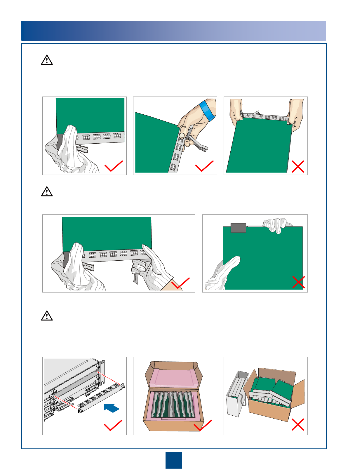
Devices and installation components
When operating devices and installation components, wear clean gloves.
Avoid direct contact with devices and installation components with bare
hands or dirty gloves.
Max 90°
4

Safety Precautions
Device safety
Before operating a device, check the electrical connection of the device to ensure that the device is securely
grounded.
Electrostatics produced by human bodies may damage electrostatic-sensitive components on boards, for
example, a large-scale integration (LSI). Therefore, take proper safety measures, such as wearing an
electrostatic discharge (ESD) wrist strap or ESD gloves, to avoid damage to the components when operating
the boards.
When operating storage batteries, take steps to prevent battery short circuits and electrolyte overflow or
leakage. Electrolyte overflow may corrode metal parts and boards, and ultimately cause equipment rust or
board short circuits.
Corrosion
Anti-corrosion measures are required if an RTN 980Lis installed in a location that is prone to corrosion. Contact
your local Huawei office for details. A location is prone to corrosion if it is:
Within 3.7 km ( 12139 ft ) of an ocean or a salt water lake
Within 3 km ( 9843 ft ) of a heavy pollution source, such as a smelting factory or coal mine
Within 2 km ( 6562 ft ) of a medium pollution source, such as a chemical, rubber, or electroplating plant
Within 1 km ( 3281 ft ) of a light pollution source, such as a food or leather processing plant or industrial boiler
Microwave
High-power radio frequency signals are harmful. Avoid exposure to transmissions from the antennas of
microwave equipment that has the radiation warning symbol . When you are installing or performing
maintenance on an antenna located on a tower that has multiple antennas, be careful not to exposure yourself
to radiation from the other antennas.
IF Cable
Before installing or removing an IF cable, turn off power switch.
5

Antenna anticorrosion requirements or measures
When outdoor equipment or cabinets are installed in a harsh environment, ensure that the following
requirements are met:
•If glue dispensing is not done on the rivets or screws of the center plate and reflective surface of an antenna
before delivery, apply matching outdoor adhesive to them.
•Apply thread adhesive to screws used for installing antennas. This can prevent the screws from becoming
loose and improve corrosion resistance.
•After you finish installing screws, spread oil or spray paint on the surface of the screws.
•In areas with many birds, install protective covers to prevent birds' droppings from corroding antennas.
Definition of harsh environment
•More than 500m ( 1640 ft ) away from but within 3.7 km ( 12139 ft ) of an ocean or a salt water lake
Installation Precautions in a Harsh Environment
Precautions for Equipment Operating Environment
The operating environment for the integrated LH complies with ETSI EN 300 019-1-3 class 3.2 standards.
Recommended operating environment
To ensure the reliability of equipment, an equipment room must be equipped with dedicated air conditioners to
control the temperature and humidity within the following ranges:
•Temperature: 15ºC to 30ºC ( 59℉to 86℉)
•Relative humidity: 40% to 75%
Basic operating environment
With stable temperature and humidity in an equipment room, the integrated LH can work under the following
conditions:
•Temperature: –5ºC to +50ºC ( 23℉to 122℉)
•Relative humidity: 5 % to 95%
6

Precautions for Elliptical Waveguide Transportation and
Storage
Do not place the drum of
the elliptical waveguide
horizontally.
Always place the drum of
the elliptical waveguide
vertically and fasten it.
7

Do not hold a board without hand protection. Wear an ESD wrist strip or ESD gloves before handling a board.
Insert filler panels into vacant slots on an NE to prevent foreign matters from getting into the
NE, which may result in faults on the NE.
Boards are fragile and valuable. When handling or placing a board, exercise caution and put it
into a dedicated packing box.
Holding a board without hand protectionWearing ESD gloves Wearing an ESD strip
Hold the front panel of a board with hands.
Instructions and Precautions for Handling Boards
CAUTION
CAUTION
CAUTION
8

1
1
2
2
3
3
1
1
2
2
3
3
Precautions for Handling the Toggle Lever Switch
•Turn the toggle lever switch only after gently
pulling it out.
•Switch off power before you remove or insert
IF cables.
•Position and description of the toggle lever switch
I: ON
O: OFF
•Turning on the switch
•Turning off the switch
Pull the switch out gently. Turn the switch. Release the switch.
CAUTION
9

Purchase List (North America)
The following table lists materials not included in Huawei auxiliary material packages. Purchase these materials
before installation. All installation operations in this document are only for your reference.
DC power
supply
(3) PDU power cable
terminal (connected to the
DC power supply) (1) PDU power
cable
(2) PDU power cable
terminal (connected to
the PDU)
(5) Ground cable terminal
(connected to the cabinet)
(4) Cabinet
ground cable
(6) Ground cable terminal
(connected to the ground
bar)
10
Item Sub-item Remarks
PDU power
cable
(1) PDU power cable It is advised to use 6 AWG electronic power cables, each
of which spans over a maximum distance of 8.8 m (29 ft).
(2) PDU power cable terminal
(connected to the PDU) Single insulated wire ferrules
(3) PDU power cable terminal
(connected to the DC power supply) Terminal specifications depend on the DC power supply.
Cabinet
ground
cable
(4) Cabinet ground cable It is advised to use 6 AWG electronic power cables.
(5) Ground cable terminal
(connected to the cabinet) Two-Hole Lug, #6AWG, 3/8" stud spacing, 25.4 mm (
1 in)
Hole Distance
(6) Ground cable terminal
(connected to the ground bar) Terminal specifications depend on the ground position.

Installation Tools
RJ45 crimping tool
Measuring tape Phillips screwdriver Flat-head screwdriver Adjustable wrenchLevel
Crimping tool
Socket suite Torque wrench Hex key Wire clippers
Wire stripper Diagonal pliers COAX crimping tool Needle-nose pliers
Combination pliersOpen-end wrench File Heat gunMultimeter
Hammer drill Marker Claw hammer Safety gloves
Segmented blade
utility knife
ESD gloves ESD wrist strap Ladder Soldering iron Impact tool
COAX stripperFiber binding tape PVC tapeVacuum cleaner Network cable tester
11

Safety belt
Installation Tools
Pulley Lifting sling Compass Flaring tool kit Hoisting grip
Hacksaw Protection belt Slip-proof glove Safety helmet
Anti-skid shoes
12

1Cabinet
Equipment Components
Branching units (BUs), RFUs, an IDU, and IF/RF cables were already installed in a cabinet before delivery.
NOTE
13
WD
H
BU
RFU
PDU
RTN 980L
IDU
600 mm ( 24 in ) 300 mm ( 12 in )
2200 mm ( 87 in )

2BU
Front Rear and side
L-shaped adapter
RF port
IF port
RFU
•An RFU has been installed on an L-shaped adapter.
•RFUs are available in RFU-SD and RFU-NonSD models. The two models
have similar appearances. An RFU-SD is used as an example.
6+0
8+0
BUs are available in two models: BU-SD and BU-NonSD. Compared with a BU-NonSD, a BU-SD has additional SD filters.
BU-SDs are used as an example.
3RFU
NOTE
NOTE
Rx filter Tx filter
SD filter
14

4IDU
Oblique View
bSide View
c
Front View
a
15
•In XPIC configuration mode, if RFUs and ISV3 boards work together, it is recommended that RFUs in the same
polarization direction connect to ISV3 boards on the same side, and the slot priority is as follows:
•Slot 13 > Slot 11 > Slot 9 > Slot 7 > Slot 5
•Slot 14 > Slot 12 > Slot 10 > Slot 8 > Slot 6
NOTE
•In 1+1 FD configuration mode, install IF boards in a 1+1 FD protection group in paired slots, and the priority of
paired slots is as follows: Slot 14 and slot12 > Slot 13 and slot 11 > Slot 10 and slot 8 > Slot 9 and slot 7 > Slot 6
and slot 4 > Slot 5 and slot 3

E plane
H plane
H plane E plane
5Cables
aFlexible waveguide
Elliptical waveguide
b
Rigid waveguide
c
Long rigid
waveguide Short rigid
waveguide
16

Installing a
Cabinet
Installing Cabinet
Cables
Installing an
Antenna
Installing an
Elliptical
Waveguide
Start
Installing Ethernet
Service Cables
Installing Fibers
Installing XPIC
Cables
Installing STM-1e
Cables
Installing E1 Cables
Installing Orderwire
Phone Cables
Installing NM
Cables
Installing Asynchronous
and Synchronous Data
Cables
Installing External
Clock Cables
Installing External
Alarm Cables
End
Assembling the
Antenna-side
Connector
Laying Out and
Installing the
Elliptical Waveguide
Hoisting the
Elliptical Waveguide
Assembling the
indoor connector
Waterproofing
Connectors
•This document uses the elliptic waveguide and dehydrator manufactured by Andrew as
examples to describe the installation. In practice, see the delivered installation guides to install
the elliptic waveguides and dehydrators actually used.
•For newly delivered equipment, BUs, RFUs, and RF cables have been installed. Installation
operations in appendixes provide reference for capacity expansion or parts replacement.
Installation Process
Grounding the
Elliptical Waveguide
Installing IF Cables
NOTE
Installing a
Dehydrator
Checking the
Installation
See the Antenna
Installation Guide.
Pages 34 to 47
Pages 48 to 49
see N63E Cabinet
Installation Guide
Pages 19 to 22
Page 55
Page 47
Pages 44 to 46
Page 34
Pages 36 to 43
Page 35
Page 34
Page 33
Page 32
Page 31
Page 30
Page 29
Page 29
Page 28
Pages 27 to 28
Page 26
Page 26
Pages 23 to 25
Installing IDU
Cables
Pages 23 to 33
Installing Ground
Cables
Laying out Cabinet
Cables
Installing Power
Cables
Page 22
Page 21
Pages 19 to 20
Checking the
Installation
Page 56 to 63
Installing Ethernet
Service Cables
Installing Fibers
Installing XPIC
Cables
Installing E1 Cables
Installing IF/RF
Cables
Page 61 to 63
Pages 60
Page 59
Pages 57 to 58
Page 56

Commissioning Process
Powering On the
Equipment
Page 50
Start
Aligning the
Antennas
Pages
52 to 54
Checking the Radio
Link Status
Page 54 Aligning the Dual-
Polarized Antennas
Pages
53 to 54
Aligning the Single-
Polarized Antennas
Pages
52 to 53
End
Configuring the NE
Data (by Using the
Web LCT)
Page 51

Ground
cable (black) -48 V power
cable (blue)
-48 V -48 V
0 V 0 V
-48 V -48 V
0 V 0 V
RTN1 (+)
NEG1 (-)
RTN1 (+)
NEG1 (-)
19
Installing Cabinet Cables
1Installing Power Cables (1/2)
1
Installing power cables
Table of contents
Other Huawei Receiver manuals