I.Scope of application
HZZGF-Z series intelligent DC high-voltage generators are mainly used for
DC withstand voltage tests on high-voltage electrical equipment such as zinc
oxide arresters, power cables, transformers, circuit breakers, generators, etc. or
DC leakage current test.
Using AIPWM technology, the inaccurate linearity of PWM technology has
been adjusted, so that the accuracy of the instrument has been greatly improved.
And use AI technology to set overvoltage protection and overcurrent protection to
replace the problem that the digital dial switch can only set the voltage value, but
cannot set the current value and voltage drift, and add AI automatic zinc oxide
arrester measurement, cable segmentation Withstand voltage test, automatic
withstand voltage test function, and can directly print the test report and save the
test report, retain the manual mode, add the function of printing under any voltage
and current, and the function of segment timing. The instrument has added
perpetual calendar and time functions, and the experimental report has time and
date.
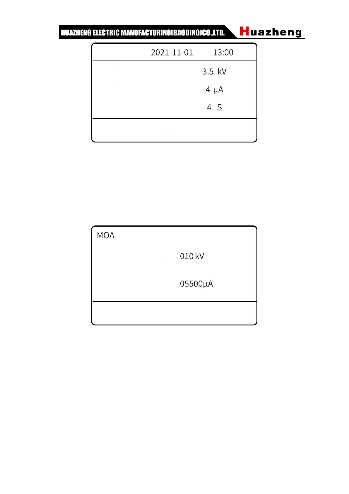
II.Technical features
Fully automatic MOA test, complete display of the process of pressure rise
and fall, pressure holding time.
Automatic cable segment withstand voltage test, complete display of the
boosting process and pressure holding time.
Automatic withstand voltage test, complete display of the process of lifting
and lowering, and the holding time.
Adopt AIPWM technology to adjust the inaccurate linearity of PWM, and the
precision has been greatly improved. Ripple coefficient≤0.2%.
With segment timing, and printing function under arbitrary voltage and
current.
The instrument has added perpetual calendar and time functions, and the
experimental report has time and date.