Energetiq LDLS EQ-400 User manual

Model EQ-400
LDLS™
Laser-Driven Light Source
Operation Manual
Revision 7 April 2018
Part Number DOC-7388

Copyright © 2018 Energetiq Technology Inc. All rights reserved.
Energetiq products are covered by the following patents: US 7435982, 7786455, 8525138,
8969841, 9048000, 9185786; Japan 5410958, 5628253; Korea 10-1507617; UK GB2450045.
All technical information, including drawings, schematics and specifications contained in this
manual are the property of Energetiq and shall not be reproduced in whole or in part without
the written consent of Energetiq. The content of this manual is subject to change without
notice.
Energetiq Technology Inc.
7 Constitution Way, Woburn, MA 01801 USA
Tel. +1 (781) 939-0763
Fax +1 (781) 939-0769
E-mail: support@energetiq.com
http://www.energetiq.com
EU Declaration of Conformity


TABLE OF CONTENTS
Chapter 1...................................................................................................................................................... 1
General Information........................................................................................................................... 1
Safety............................................................................................................................................... 1
Chapter 2...................................................................................................................................................... 9
Description ........................................................................................................................................... 9
General ........................................................................................................................................... 9
Specifications............................................................................................................................... 10
System Description .................................................................................................................... 12
Power/Control Unit (PCU) ..................................................................................................... 13
Lamp House................................................................................................................................ 14
Chapter 3.................................................................................................................................................... 17
Installation........................................................................................................................................... 17
Unpacking.................................................................................................................................... 17
Installation Procedure .............................................................................................................. 17
Chapter 4.................................................................................................................................................... 21
Operation............................................................................................................................................ 21
Starting.......................................................................................................................................... 21
Stopping ....................................................................................................................................... 21
Manual Reset............................................................................................................................... 22
Serial Interface ............................................................................................................................ 22
Appendix A................................................................................................................................................ 25
Engineering Drawings...................................................................................................................... 25
Appendix B................................................................................................................................................ 27
Revision History ................................................................................................................................ 27

EQ-400 Operation Manual Rev. Error! Reference source not found. 1
C h a p t e r 1
GENERAL INFORMATION
Safety
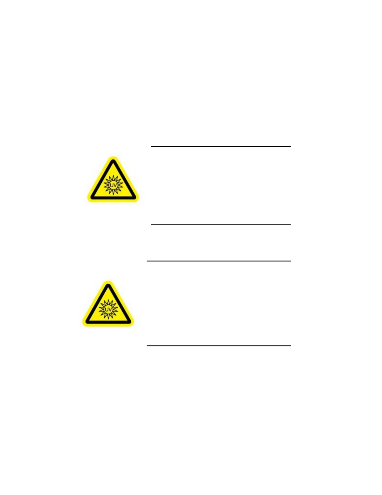
WARNING
CAUTION
This unit emits ultraviolet (UV) radiation that is
harmful to humans. Avoid exposure to the
direct or reflected output beam. Make certain
that the appropriate output beam shields and
optics are in place prior to energizing the unit.
All interlocks must be satisfied prior to
operation; failure to do so may lead to
hazardous conditions.
The EQ-400 emits dangerous levels of UV
radiation. Even short exposures to skin or eyes
may cause burns. Ensure that only authorized
personnel are in the vicinity of source during
operation. Personnel in vicinity of operating
source should wear protective eyewear, clothing,
and gloves. Lighted UV warning lights and signs
posted on doors to lab areas may help prevent
accidental exposure.

2 EQ-400 Operation Manual Rev. Error! Reference source not found.
WARNING
General Precautions
The output beam from the EQ-400 should be blocked when not in use with an electronic
shutter or other appropriate beam blocking device. Due to the possibility of generating ozone
with some models of EQ-400 when ambient oxygen is exposed to short wavelength light, the
beam should always be enclosed in an appropriate beam pipe, tube, or enclosed space. We
suggest purging any beam transport space with dry nitrogen gas.
The EQ-400 source must also be cabled correctly and connected to a power source with a
protective earth ground prior to operation.
Refer to the Installation section of this manual in Chapter 3 for details of the facilities
connections.
There are no user-serviceable parts inside the EQ-400. For any problems encountered during
operation, please contact Energetiq Technology for assistance. If there is a component
failure, do not attempt to open the Power/Control Unit or Lamp House enclosure of
the EQ-400.
No regular maintenance is required for the EQ-400. Any service to the system must be
performed only by factory authorized and trained technicians. To avoid injury, under no
circumstances should the user open or modify the Lamp House or Power/Control Unit
enclosure.
The unit must not be operated if the covers are removed or it is defective in any way. Contact
Energetiq if any problems with the equipment are suspected.
The EQ-400 utilizes a quartz lamp containing a high-pressure gas fill. Explosion of
the lamp and possible injury from flying fragments can occur if the lamp is
mishandled.
Do not open the enclosure of either the Lamp House or the Power/Control Unit.
Dangerous invisible infrared laser beams and hazardous voltages exist inside the
Lamp House. Opening the chassis both voids the warranty and exposes the user to
dangerous radiation and hazardous voltages.
The EQ-400 utilizes an internal Class 4 IR laser
capable of causing severe injury to eyes or skin.
Do not open or attempt to service this unit.
Contact Energetiq regarding any problems with
the unit.

EQ-400 Operation Manual Rev. Error! Reference source not found. 3
CAUTION
The EQ-400 is a Class 4 Laser Product. All appropriate laser safety measures should be in
place before operating the system. Consult your facility's laser safety officer. Laser protective
eyewear should be worn at all times while operating the system.
The EQ-400 also produces high-intensity UV radiation. Eyewear should protect not only from
laser radiation at 1070 nm, but also from UV radiation in the band from 190 to 400 nm.
For further safety information, refer to ANSI Z136.1 Standard for Safe Use of Lasers,
available from Laser Institute of America (www.laserinstitute.org).
Laser Information
The EQ-400 uses a patented* laser drive system to excite a plasma that radiates in the UV as
well as the visible bands. A Class 4 laser is located in the Power/Control Unit enclosure. The
optical configuration of the Lamp House ensures that the direct laser beam cannot exit the
unit. The EQ-400 laser product is designated as Class 4 during all normal operation.
The parameters of the non-accessible internal laser are given below in Table 1.
Wavelength
1070 nm
Emission Type
CW
Laser Power for classification
400W
Beam Diameter
5 mm
Divergence
0.3 mRad
Transverse Beam Mode
Single Mode
Table 1: Embedded Laser Parameters
*US 7435982, 7786455, 8525138, 8969841, 9048000, 9185786 ; Japan 5410958, 5628253; Korea 10-1507617; UK
GB2450045; others pending
Use of controls or adjustments or performance of procedures
other than those specified herein may result in hazardous
radiation exposure.
INVISIBLE LASER RADIATION
AVOID EYE OR SKIN EXPOSURE TO
DIRECT OR SCATTERED RADIATION
CLASS 4 LASER PRODUCT

4 EQ-400 Operation Manual Rev. Error! Reference source not found.
Nominal Ocular Hazard Distance (NOHD) based on 400W 1070nm pump laser under a
failure mode condition where aperture is itself accessible: 4 meters
Required Optical Density (OD) for safety eyewear: 6 or higher at 1070 nm
These values are based on a theoretical failure condition.
Labels and Safety Notification
The following safety labels appear on the product. Figure 1 shows the location of each label
on the EQ-400 system.
UV Hazard warning label –indicates hazardous levels of UV
light are present.
Manufacturer’s identification label – gives the manufacturer’s
name and address, and the model, serial number, and date of
manufacture of the equipment.
Explanatory label –states the classification of the laser product.
Certification label –states that the equipment has been tested
and verified to meet the standards indicated.
Aperture label –indicates the outlet aperture for laser radiation

EQ-400 Operation Manual Rev. Error! Reference source not found. 5
Hazard warning label –indicates that a laser hazard is present
Protective housing label –warns of an enclosed laser radiation
hazard
Protective housing label –warns of an enclosed laser radiation
hazard

6 EQ-400 Operation Manual Rev. Error! Reference source not found.
Aperture Label
Manufacturer’s
Identification label
UV Hazard
Warning Label
Hazard Warning
Label
Protective
Housing Label
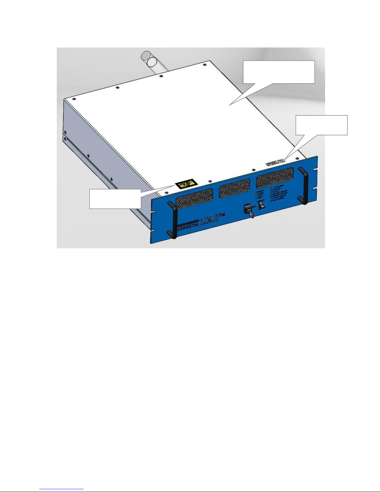
EQ-400 Operation Manual Rev. Error! Reference source not found. 7
Figure 1: Safety Label Locations
Safety Interlocks
The EQ-400 is equipped with interlocks to prevent operation of the device when any of the
following conditions are present:
1. A remote interlock is open
2. Lamp House cover not installed
3. Laser fiber not connected to Lamp House
4. Power/Control Unit cover not in place
Explanatory
Label
Certification
Label
Protective Housing Label
(inside chassis on laser
module)

8 EQ-400 Operation Manual Rev. Error! Reference source not found.
Remote Interlock
Remote interlock pins are provided for the customer’s use (see Chapter 3 for connection
details). Any suitable normally-open contact or solid-state switch can operate the interlock
circuit. The contact or switch should be rated for 8mA minimum at 5VDC.
The interlock circuit must be connected to enable the operation of the unit. Should the
interlock connection open during operation or standby, the source is immediately disabled, and
all light output from the aperture ceases.

EQ-400 Operation Manual Rev. Error! Reference source not found. 9
C h a p t e r 2
DESCRIPTION
General
The EQ-400 is a broad-band lamp system for use in a wide variety of applications. The lamp
produces high brightness, broad-band light from DUV wavelengths through visible and
beyond. The output is very stable, and has a long lifetime before any service is required. A
simple control interface ensures ease of use.
Some of the advantages of the EQ-400 include:
Very high brightness across complete spectrum
–190nm through visible and beyond
Eliminates need for multiple lamps (replaces D2/Tungsten/Xenon Arc)
–Simplified optical system
Excellent spatial stability
–Repeatable measurements
Superior short and long term power stability
–Repeatable measurements
Electrodeless operation for long life
–Reduced consumable costs
–Minimal recalibration of instrument
The EQ-400 system consists of a Power/Control Unit (PCU), Lamp House unit, and
interconnecting cable. Connection to AC power is required for operation. Connections to
nitrogen purge gas and cooling water are required. See Chapter 3 for connection details.

10 EQ-400 Operation Manual Rev. Error! Reference source not found.
Specifications
Optical Performance
Typical output spectrum: see Figure 2.
Figure 2: Typical Output Spectrum
Physical Specifications
Dimensions (H x W x D)
Lamp House: 136 x 145 x 56 mm (5.4 x 5.7 x 2.2 in)
Power/Control Unit: 133 x 483 x 584 mm (5.2 x 19.0 x 23.0 in)
Weight
Lamp House: 2.7 kg (6.0 lb)
Power/Control Unit: 18.8 kg (41.5 lb)
Utility Requirements
Electrical: 200 –240 V~, 50/60 Hz, 7A, 1700 W max.
Purge gas: clean dry nitrogen, filtered to 5um, 20 psig (0.14 MPa) supply pressure,
maximum flow rate 0.7 liters/minute
–Fittings: 4mm push-to-connect
Cooling water (Power/Control Unit): 3 –4 liters/minute, 18 –24 °C
–Fittings: 8mm push-to-connect
Cooling water (Lamp House): >= 1 liter/minute, 18 –30 °C
–Fittings: 8mm Swagelok

EQ-400 Operation Manual Rev. Error! Reference source not found. 11
Remote Interface
Digital Inputs
Type: Optocoupler LED
Logic: Active High
Input voltage: 5VDC
Input current: 8mA
Digital Outputs
Type: Open collector to ground (digital common)
Logic: Active Low
Voltage: 30VDC max.
Sink current: 30mA max.
User Power
Voltage: 5VDC, referenced to digital common
Current: 200mA maximum
Serial Interface
Type: RS-485 4-wire (full duplex)
Connector: Male 9-pin d-sub
Termination: 120 ohms across receiver input (pins 2 and 7)
Interface protocol: see Chapter 4.
Port settings: 9600 bps, 8 data bits, 1 stop bit, no parity, no handshaking
Environmental Requirements
Operating
Ambient temperature: 15–35°C
Relative Humidity: non-condensing, 80% max. for temperatures up to 31°C,
decreasing linearly to 50% max. at 35°C.
Pollution Degree 2 (normally only non-conductive pollution; occasional,
temporary condensation possible)
Installation Category II
Indoor use only
Transport
Temperature: -5–70°C
Relative Humidity: non-condensing, 95% max.
12 EQ-400 Operation Manual Rev. Error! Reference source not found.
System Description
The EQ-400 system consists of a Power/Control Unit (PCU), Lamp House, Controller to
Lamp House interconnect cable, and power input cable. Laser light is generated in the PCU
and transmitted to the Lamp House by an optical fiber permanently attached to the PCU.
The following sections provide descriptions of the system components and controls, and give
an overview of their functions. Refer to the “Installation” section of this manual (Chapter 3)
for more detailed information.
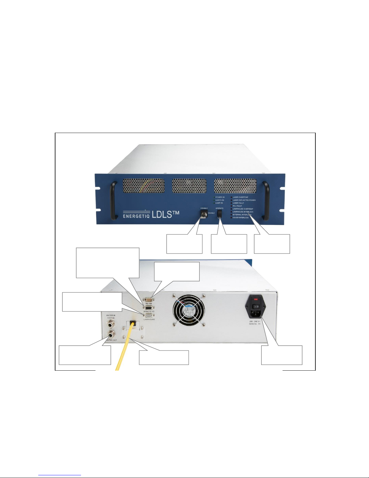
Figure 3: EQ-400 Power/Control Unit
Power Input
Connector
RS-485
Connector
Lamp House Control
Connector
Water inlet/outlet
fittings
Status
Indicators
I/O Interface
Connector
(includes remote
interlock connection)
Laser fiber
Operate
switch
Key
switch

EQ-400 Operation Manual Rev. Error! Reference source not found. 13
Power/Control Unit (PCU)
The Power/Control Unit contains:
Laser module
Laser power supply
Control electronics
Status indicator LEDs
Operate switch
Keyswitch
Interface connectors
Cooling water connectors
External features (refer to Figure 3):
Status Indicator LEDs
These LEDs indicate the system status. The function of these indicators is shown below in
Table 2.
LED Label
Meaning (when lit)
POWER OK
AC power is connected to the EQ-400 PCU
LAMP ON
UV Light is on
LASER ON
Laser power is ON and laser light is being produced within the Lamp
House
REMOTE
System is in remote control mode
LASER OVERTEMP
Laser internal temperature too high
LASER FAULT
Laser module internal fault
PCU FAULT
One of the following has occurred in the Power/Control Unit:
1. Controller internal temperature too high
2. Laser power not reaching setpoint
3. Internal power supply voltage low
4. Lamp failed to ignite
LAMPHOUSE OVERTEMP
Lamphouse internal temperature too high
LAMPHOUSE INTERLOCK
One of the following has occurred in the Lamp House module:
1. Control Cable not connected properly
2. Laser fiber not connected properly
EXTERNAL INTERLOCK
External interlock open
COVER INTERLOCK
PCU cover(s) not in place
Table 2: Status Indicator LED Functions

14 EQ-400 Operation Manual Rev. Error! Reference source not found.
Operate switch
Turns the lamp on or off.
Key switch
Enables or disables operation of the lamp. The keyswitch must be in the ENABLE position
for the lamp to operate. The key can only be removed in the DISABLE position.
I/O Interface Connector
Provides access to control and status signals. Control signals are only active when the system
is in remote control mode. See Chapter 3 for pin assignments and functions.
This connector also functions as the remote interlock connector.
Lamp House Control Connector (9-pin D-sub)
Provides various power and control signals to/from the Lamp House module. No other
connector or cable may be used with the EQ-400 other than the one supplied.
RS-485 Connector (9-pin D-sub)
Connector for optional RS-485 interface. See Chapters 3 and 4 for electrical details and
commands.
Power Input Connector
This is a fused IEC 320 inlet connector for AC power input. Fuses are 5 x 20mm, 10A, 250V,
time delay type. See Chapter 3 for detailed information.
Water inlet/outlet fittings
Connections for cooling water for the internal laser module.
Laser fiber
Transmits laser energy from the PCU to the Lamp House.
Lamp House
The Lamp House assembly contains:
Lamp
Igniter
IR pumping optics
Output windows
Laser ON indicator
Control connector
Table of contents
Other Energetiq Portable Generator manuals

Popular Portable Generator manuals by other brands

Westinghouse
Westinghouse iGen1200 user manual

Champion Global Power Equipment
Champion Global Power Equipment 500559-EU Operator's manual

BANDELIN
BANDELIN SONOREX TECHNIK TG Series Assembly instructions

pela tools
pela tools BK10 manual

Westinghouse
Westinghouse WGen5300 user manual

Winco
Winco DR130F4 Installation and operator's manual


