4
©Hubbell Incorporated | hubbellpowersystems.com
TD10321E Rev. B - 07/2021
©Hubbell Incorporated | hubbellpowersystems.com
TD10321E Rev. B - 07/2021
Overview
QUALIFIED PERSON
Only qualified trained and
competent personnel that
understand proper safety
procedures must select, install
and service this equipment.
Read and understand these
instructions before installing,
operating or maintaining this
equipment.
This guide is not a substitute for
adequate training and experience
in safety procedures for this type
of equipment.
SIGNAL WORDS
The signal words “DANGER”,
“WARNING” and “CAUTION”
(along with their assigned symbol)
throughout this manual indicate
the degree of hazard the user may
encounter. These symbols and
words are defined as:
DANGER
!
DANGER indicates an imminently
hazardous situation which, if not
avoided, will result in death or
serious injury.
WARNING
!
WARNING indicates a potentially
hazardous situation which, if not
avoided, could result in death or
serious injury.
CAUTION
!
CAUTION indicates a potentially
hazardous situation which, if not
avoided, may result in minor or
moderate injury.
CAUTION
CAUTION used without the safety
alert symbol indicates a potentially
hazardous situation which, if not
avoided, may result in property
damage.
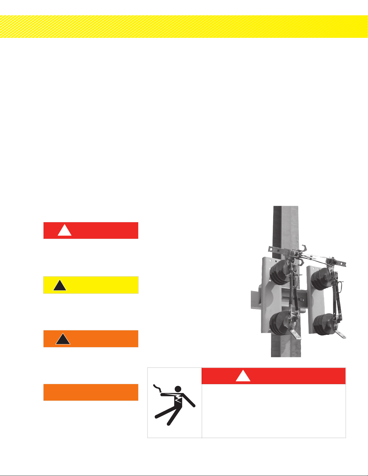
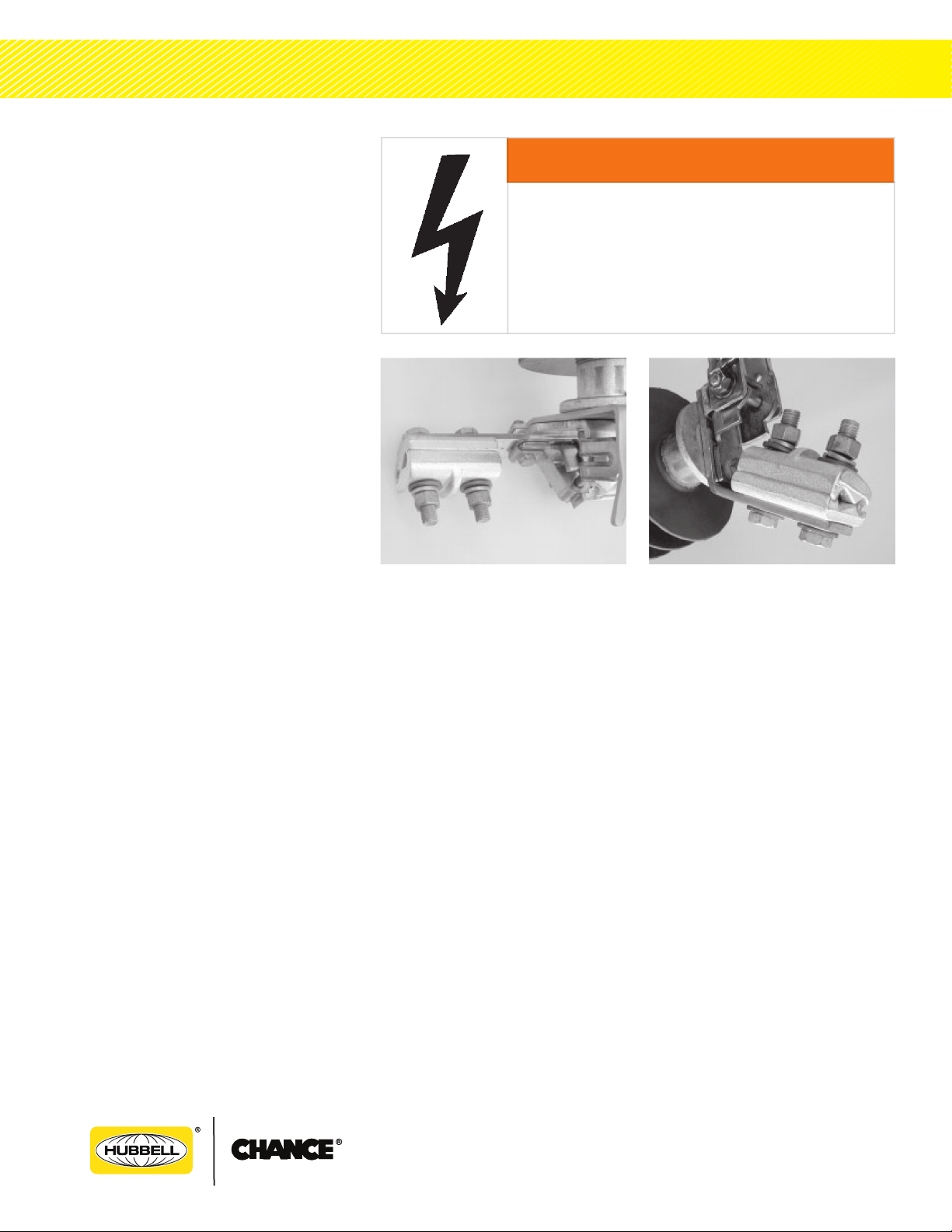
PRODUCT
The products covered by this
manual are the BP3 3-Pull
overhead by-pass switches
for medium voltage electrical
distribution switching.
These products are designed for
distribution switching only at
their rated capacities. They
cannot be field modified for
capacities other than what was
shipped with the units. If a
dierent capacity is desired,
contact your supervisor or factory
representative
FUNCTION
These products are non-loadbreak
disconnect switches designed to
provide a means for by-passing,
disconnecting and isolating
reclosers or similar devices on
the electrical distribution system.
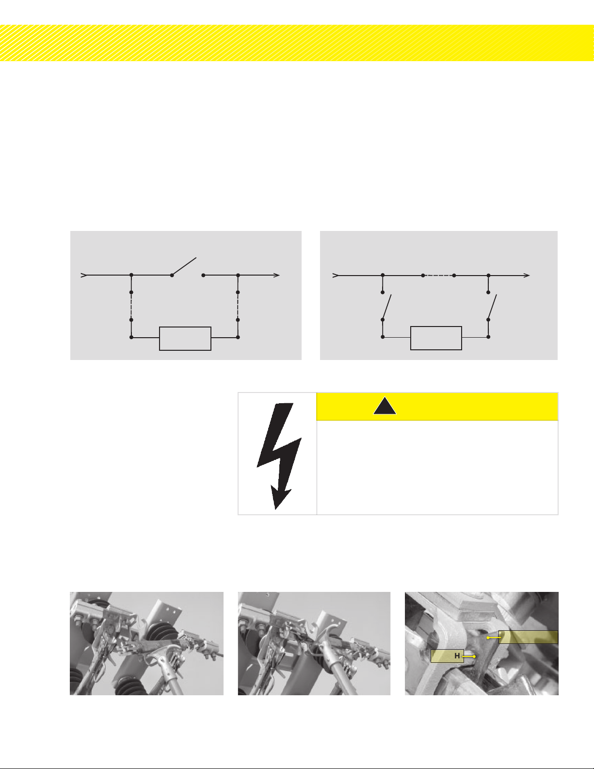
GENERAL
The BP3 By-Pass Switch is a
single-phase 3-blade, 3-pull,
hookstick operated switch. It is
used for manually disconnecting
a recloser without interrupting
normal electricalservice. Standard
variations are:
1. Right or left opening by-pass
blade operation
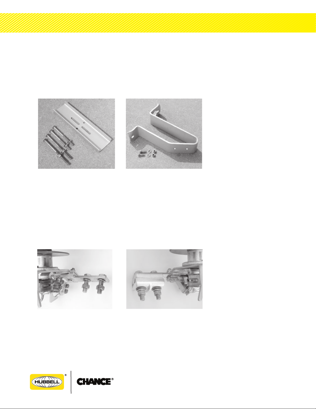
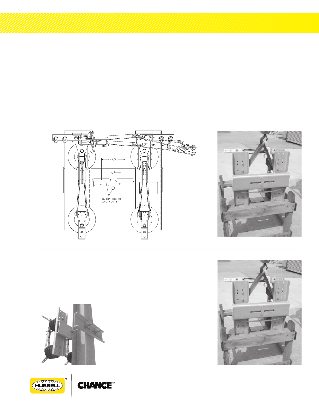
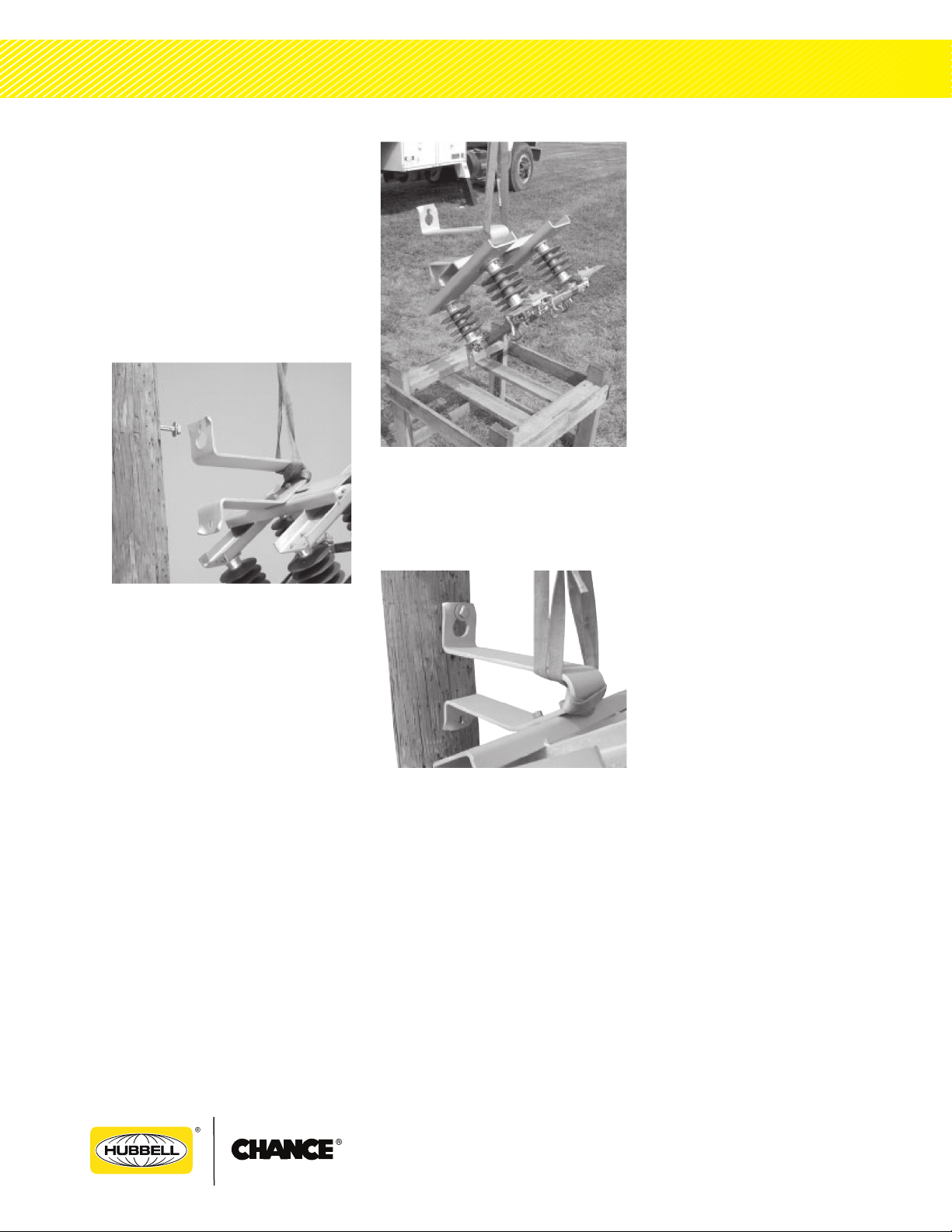
2. Switch mounting
3. Terminal connections
4. Loadbreak hooks on
disconnect blades.
The BP3 switch has no inherent
current making or breaking capacity.
The by-pass blade includes a hook
for use with a loadbreak tool. The
BP3 has no deadending provisions.
SPECIFICATIONS
Select the proper BP3 switch for
each installation with consideration
to voltage, continuous current,
short time current withstand,
lightning impulse withstand and
variations. If there is concern about
the use of this switch as rated,
consult your supervisor before
installation.
• Nominal voltage ratings of
15.0 kV, 27 kV or 38 kV
• Lightning Impulse peak
withstand ratings of 110 kV,
125 kV, 150 kV and 200 kV
• Continuous current rating of
600 or 900A (900A only for
units with 200 kV BIL rating)
• Short time current withstand
rating: 25 kA Symmetrical,
1 second 65 kA peak
Hazardous Voltage
Will cause severe personal injury, death, or property
damage.
Only qualified personnel should work on or around
this equipment after becoming thoroughly familiar
with this document and other publications regarding
this equipment.
DANGER
!