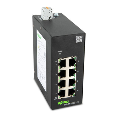
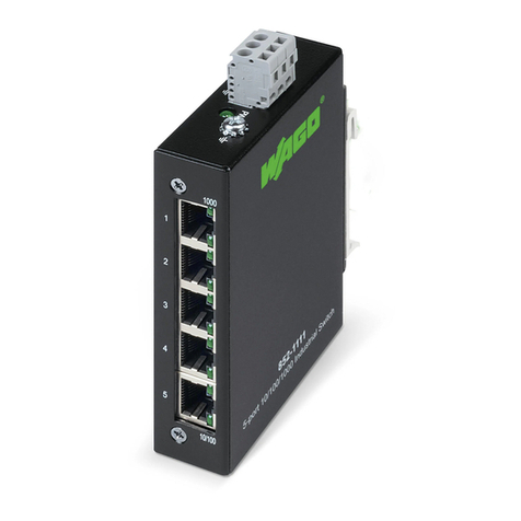
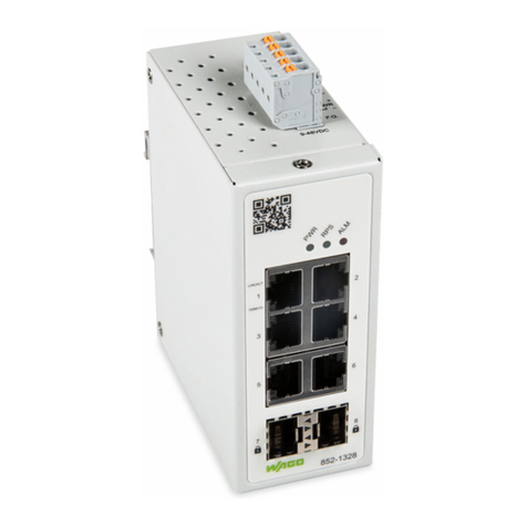
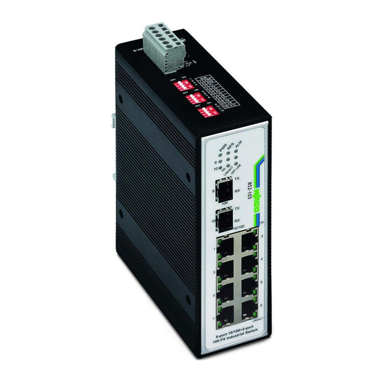
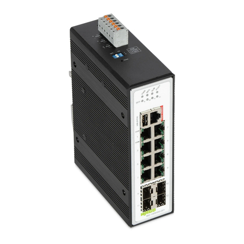
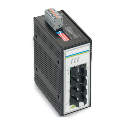
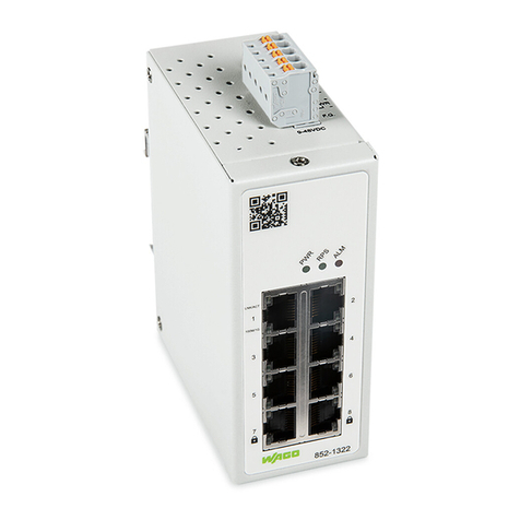
WAGO 852-1322 User manual

Pos: 2 /D o kum enta tion allge mein/E in ban d/E inba nd Frontsei t e -H andbuch ; CI 2017; mitD oc Varia bl en (Standar d) @28 \mo d_1 486 4775 029 10_ 0.do cx @ 4053 88 @ @ 1
Manual
852-1322
Managed Switch
; 8 Port Gb; MACsec
852
-1328
Managed Switch; 6 Port Gb; 2FOC;
MACsec
1.0.1
Pos: 3 /A ll e Se rien (All ge meine Module )/Rec ht liches , Allgem eines/ I mpres s um f ür St anda rdh and büc h er - al lg . A nga ben , Ans ch rifte n, T el efo nnu mmern und E -Mai l-Adr ess en @3\mo d_12 191 511 182 03_ 21.d ocx @ 210 60 @ @ 1

2
852-1322/852-1328
Manual
1.0.01
© 2020 WAGO Kontakttechnik GmbH & Co. KG
All rights reserved.
WAGO Kontakttechnik GmbH & Co. KG
Hansastraße 27
D-32423 Minden
Phone: +49 (0) 571/8 87 – 0
Fax: +49 (0) 571/8 87 – 1 69
E-Mail: info@wago.com
Web: www.wago.com
Technical Support
Phone: +49 (0) 571/8 87 – 4 45 55
Fax: +49 (0) 571/8 87 – 84 45 55
E-Mail: support@wago.com
Every conceivable measure has been taken to ensure the accuracy and
completeness of this documentation. However, as errors can never be fully
excluded, we always appreciate any information or suggestions for improving the
documentation.
E-Mail: documentation@wago.com
We wish to point out that the software and hardware terms as well as the
trademarks of companies used and/or mentioned in the present manual are
generally protected by trademark or patent.
WAGO is a registered trademark of WAGO Verwaltungsgesellschaft mbH.
===E nde der List e für Textma rkeE in ban d_vo rne ===

Table of Contents 3
852-1322/852-1328 Industrial Managed Switch
Manual
1.0.01
Pos: 5 /D o kum enta tion allge mein/V e rzeic hnisse/ Inhal tsv erz eichni s -Ü bersc hrift oG und Ve rzei c hnis @ 3\mod_ 121 915 1230 875 _21 .docx @21 063 @ @ 1
Table of Contents
1Notes about this Documentation .............................................................6
1.1 Validity of this Documentation.................................................................6
1.2 Copyright................................................................................................6
1.3 Symbols .................................................................................................7
1.4 Number Notation ....................................................................................9
1.5 Font Conventions ...................................................................................9
2Important Notes.......................................................................................10
2.1 Legal Bases..........................................................................................10
2.1.1 Subject to Changes..........................................................................10
2.1.2 Personnel Qualification ....................................................................10
2.1.3 Proper Use of the Industrial Switches...............................................10
2.1.4 Technical Condition of Specified Devices.........................................11
2.1.5 Standards and Regulations for Operating the Industrial Switches ....11
2.1 Safety Advice (Precautions)..................................................................12
3Device Description..................................................................................15
3.1 View .....................................................................................................16
3.1.1 Front View........................................................................................16
3.1.2 Top View..........................................................................................17
3.2 Connectors...........................................................................................18
3.2.1 Grounding screw..............................................................................18
3.2.2 Power Supply (PWR/RPS)...............................................................19
3.2.3 Network Connections.......................................................................20
3.2.3.1 10/100/100BASE-T-Ports ............................................................21
3.2.3.2 100/1000BASE-SX/-LX-Ports ......................................................21
3.3 Display Elements..................................................................................22
3.3.1 Unit-LEDs ........................................................................................22
3.3.2 Port-LEDs ........................................................................................22
3.4 Label ....................................................................................................23
3.4.1 Device label description ...................................................................23
3.5 Technical Data .....................................................................................24
3.5.1 Device Data .....................................................................................24
3.5.2 System Data ....................................................................................24
3.5.3 Power Supply...................................................................................24
3.5.4 Communication ................................................................................24
3.5.5 Environmental Conditions ................................................................25
3.6 Approvals .............................................................................................26
4Mounting..................................................................................................27
4.1 Installation Site .....................................................................................27
4.2 Installation on a Carrier Rail..................................................................27
4.3 Removal from Carrier Rail ....................................................................27
5Connect Devices .....................................................................................28
5.1 Power Supply .......................................................................................28
5.2 100/1000Base-SX/LX Port, Fiber Optic (Only for SFP model) ..............29
5.3 10/100/1000BASE-T Ports ...................................................................30

4 Table of Contents
852-1322/852-1328 Industrial Managed Switch
Manual
1.0.01
6Function Description ..............................................................................31
6.1 Security ................................................................................................31
6.1.1 IEEE 802.1X ....................................................................................31
6.1.2 RADIUS ...........................................................................................32
6.1.3 MACSec...........................................................................................32
7Configuration in the WBM ......................................................................33
7.1 Login ....................................................................................................33
7.2 Login Failure.........................................................................................37
7.3 Information ...........................................................................................40
7.3.1 System Information ..........................................................................40
7.3.2 Legal Information .............................................................................41
7.3.2.1 WAGO Licenses..........................................................................41
7.3.2.2 Open Source Licenses ................................................................41
7.4 Configuration........................................................................................42
7.4.1 System Settings...............................................................................42
7.4.2 Network Settings..............................................................................43
7.4.3 Port Settings ....................................................................................45
7.4.4 Password .........................................................................................48
7.4.5 Clock................................................................................................49
7.5 Diagnostics...........................................................................................51
7.5.1 SNMP ..............................................................................................51
7.5.1.1 SNMP Agent................................................................................54
7.5.1.2 SNMP V1/V2c Community...........................................................54
7.5.1.3 SNMP Trap..................................................................................56
7.5.1.4 SNMP V3 Auth. ...........................................................................57
7.5.2 Modbus TCP....................................................................................59
7.5.3 System Log......................................................................................61
7.5.3.1 Setting .........................................................................................61
7.5.3.2 Log ..............................................................................................62
7.5.4 Port Monitor .....................................................................................65
7.6 Security ................................................................................................66
7.6.1 Static SAK Setting............................................................................66
7.6.2 Secure Code....................................................................................68
7.6.3 IEEE 802.1X ....................................................................................69
7.6.3.1 IEEE 802.1X Settings ..................................................................70
7.6.3.2 IEEE 802.1X Parameters Settings...............................................71
7.6.3.3 IEEE 802.1x Port Setting.............................................................72
7.7 Maintenance.........................................................................................74
7.7.1 Firmware Upgrade ...........................................................................74
7.7.2 Reset to Default ...............................................................................75
7.7.3 Backup/Restore ...............................................................................76
7.7.4 Reboot .............................................................................................77
7.7.5 Logout..............................................................................................78
8Appendix..................................................................................................79
8.1 Modbus Memory Map...........................................................................79
List of Figures ..................................................................................................81
List of Tables ....................................................................................................83
Table of Contents 5
852-1322/852-1328 Industrial Managed Switch
Manual
1.0.01
===E nde der Li ste für Tex tma rke V e rzeic hni s_v orn e = ==

6 Notes about this Documentation
852-1322/852-1328 Industrial Managed Switch
Manual
1.0.01
-Übe rs chri ft 1 @3\mod _12 337 5608 465 6_2 1.do c x @ 2 709 6 @ 1@ 1
1 Notes about this Documentation
Pos: 8 /A ll e Se rien (All ge meine Module )/S iche rheits -und s o nstig e H inwei s e/Hi nweis / Hinw eis: D okument ation aufbew a hre n @ 4\mod_1 237 987 339 812 _21. docx @29 026 @ @ 1
Always retain this documentation!
This documentation is part of the product. Therefore, retain the documentation
during the entire service life of the product. Pass on the documentation to any
subsequent user. In addition, ensure that any supplement to this documentation
is included, if necessary.
Pos: 9 /A ll e Se rien (All ge meine Module )/Übe rsc h rifte n/E ben e 2/ Gülti gk eits be reic h - Ü bers c hrift 2@ 12\mod_13 3891 244 877 6_2 1.do c x @ 9 646 9 @ 2@ 1
1.1 Validity of this Documentation
Pos: 10 /S erie 852 (ETHE RN E T -Z ubeh ör )/Hinw eis e zu r D oku me ntatio n/G ül tigk eits ber ei ch Do kum enta ti on 852-xxxx@ 16\mod_13 784 582 086 96_ 21.d ocx @ 130868 @ @ 1
This documentation is only applicable to WAGO ETHERNET accessory products
“Managed Switch” (852-1322/852-1328).
Pos: 11. 1 / All e Se ri en (A ll gemei ne Module) /Übe rsc hri ften /E ben e 2/U rhe bersc hut z -Üb ersc hrift 2 @ 2 3\mod_ 143 564 704 2188 _21 . docx @1 848 08 @ 2@ 1
1.2 Copyright
Pos: 11. 2 / All e Se ri en (A ll gemei ne Module) /Rec htlic hes , Al lg emei nes /U rhe bers chutz ausf ührlic h@ 4\mo d_1 235 565 145 234 _21. docx @27 691 @ @ 1
This Manual, including all figures and illustrations, is copyright-protected. Any
further use of this Manual by third parties that violate pertinent copyright
provisions is prohibited. Reproduction, translation, electronic and phototechnical
filing/archiving (e.g., photocopying) as well as any amendments require the
written consent of WAGO Kontakttechnik GmbH & Co. KG, Minden, Germany.
Non-observance will involve the right to assert damage claims.
Pos: 11. 3 / Dok ume ntati on al l gem ein/G lie de rung sel e ment e/- --Sei t enw ec hsel ---@3\mod_122 110 804 507 8_0. docx @ 21 810 @ @ 1

Notes about this Documentation 7
852-1322/852-1328 Industrial Managed Switch
Manual
1.0.01
Pos: 11. 4 / All e Se ri en (A ll gemei ne Module) /Übe rsc hri ften /E ben e 2/S y mbole -Üb ersc hri ft 2@ 13\mod_135 106 804 240 8_2 1.doc x @ 1 052 70 @ 2 @ 1
1.3 Symbols
Pos:11. 5.1 / All e S eri e n (All ge mein e M odul e)/S iche rh ei ts- und s onsti geHinw eise/G efah r/G efah r: _W arn ung v or P e rso nensc häd en al l gem ein_ -Erläuterung @13\mod_ 1343 309 450 020 _21. docx @10 102 9 @ @1
Personal Injury!
Indicates a high-risk, imminently hazardous situation which, if not avoided, will
result in death or serious injury.
Pos: 11. 5. 2 /Al le S eri e n (All ge mein e M odul e)/S iche rh ei ts- und s onst i ge Hi nw eise/ G efah r/G efah r: _W arn ung v or P e rso nensc häd en d urc h el ekt ris ch en Str om_ -Erl äuterun g @ 13\mod_134 330 969 491 4_2 1.docx @ 1 010 30 @ @ 1
Personal Injury Caused by Electric Current!
Indicates a high-risk, imminently hazardous situation which, if not avoided, will
result in death or serious injury.
Pos: 11. 5. 3 /Al le S eri e n (All ge mein e M odul e)/S iche rh ei ts- und s onst i ge Hi nw eise/ Wa rnu ng/Wa rnu ng: _War nun g vo r Pers onen s chä den allge mein _ -E rl äute run g @ 13\mod_134 330 987 704 1_2 1.doc x @1 010 35 @ @ 1
Personal Injury!
Indicates a moderate-risk, potentially hazardous situation which, if not avoided,
could result in death or serious injury.
Pos: 11. 5. 4 /Al le S eri e n (All ge mein e M odul e)/S iche rh ei ts- und s onst i ge Hi nw eise/ Vo rsi cht/V o rsicht: _Wa rnu ng vo r Per s one nsch äde n all ge mei n_ - Erl äut eru ng @ 13\mod_13 433 100 287 62_ 21.d ocx @ 101038 @ @ 1
Personal Injury!
Indicates a low-risk, potentially hazardous situation which, if not avoided, may
result in minor or moderate injury.
Pos: 11. 5. 5 /Al le S eri e n (All ge mein e M odul e)/S iche rh ei ts- und s onst i ge Hi nw eise/ Acht ung/ Ac htun g: _W arnung vorS ac hsch äde n all g emei n_ -Erläu t erung @ 13 \mod_1 343 310 1346 23_ 21. doc x @ 101041 @ @ 1
Damage to Property!
Indicates a potentially hazardous situation which, if not avoided, may result in
damage to property.
Pos: 11. 5. 6 /Al le S eri e n (All ge mein e M odul e)/S iche rh ei ts- und s onst i ge Hi nw eise/ Acht ung/ Ac htun g: _W arnung vorS ac hsch äde n du rch elekt rosta ti sche Auflad ung _ - E rl äute ru ng @ 13\mod_13 4331 022 770 2_2 1.do cx @ 1 010 44 @ @1
Damage to Property Caused by Electrostatic Discharge (ESD)!
Indicates a potentially hazardous situation which, if not avoided, may result in
damage to property.
Pos: 11. 5. 7 /Al le S eri e n (All ge mein e M odul e)/S iche rh ei ts- und s onsti ge Hinw ei se/Hinw ei s/Hinw eis : _Wichti ger Hinwei s all gemei n_ - E rl äute run g @ 13\mod_ 134 331 032 690 6_21 .docx @1 010 47 @ @1
Important Note!
Indicates a potential malfunction which, if not avoided, however, will not result in
damage to property.
Pos: 11. 5. 8 /Al le S eri e n (All ge mein e M odul e)/S iche rh ei ts- und s onsti ge Hinw ei se/I nformati on/I nfor mati on: _Weite re I nfor mati on al l gem ein_ -Erl ä uter ung @ 1 3\m od_1 343 310 439 814 _21. doc x @10 105 1 @ @ 1

8 Notes about this Documentation
852-1322/852-1328 Industrial Managed Switch
Manual
1.0.01
Additional Information:
Refers to additional information which is not an integral part of this
documentation (e.g., the Internet).
Pos: 11. 6 / Dok ume ntati on al l gem ein/G lie de rung sel e ment e/- --Sei t enw ec hsel ---@3\mod_122 110 804 507 8_0. docx @ 21 810 @ @ 1

Notes about this Documentation 9
852-1322/852-1328 Industrial Managed Switch
Manual
1.0.01
Pos: 11. 7 / All e Se ri en (A ll gemei ne Module) /Übe rsc hri ften /E ben e 2/D arst ell ung der Za hlens y ste me - Übe rsc hri ft 2 @23 \mo d_1 435 6471 280 78_ 21.d ocx @ 184 811 @2 @1
1.4 Number Notation
Pos: 11. 8 / All e Se ri en (A ll gemei ne Module) /Rec htlic hes , Al lg emei nes / Zahl ensyst em e @ 3 \mo d_1 221 059 4540 15_ 21. doc x @ 21711 @ @ 1
Table 1: Number Notation
Number Code
Example
Note
Decimal
100
Normal notation
Hexadecimal
0x64
C notation
Binary
'100'
'0110.0100'
In quotation marks, nibble separated
with dots (.)
Pos: 11. 9 / All e Se ri en (A ll gemei ne Module) /Übe rsc hri ften /E ben e 2/S ch riftko nv en tione n - Ü be rs chrif t 2 @ 23\mod_14 356 471 860 05_ 21.d oc x @ 184814 @2 @1
1.5 Font Conventions
Pos: 11. 10 / All e Se ri en (A ll ge mein e Mo dule )/Rec htliches , Al lgem eines /Schriftk onv ent io nen @3\mod _12 210 5952 143 7_2 1.do cx @ 2171 4 @ @ 1
Table 2: Font Conventions
Font Type
Indicates
italic
Names of paths and data files are marked in italic-type.
e.g.: C:\Program Files\WAGO Software
Menu
Menu items are marked in bold letters.
e.g.: Save
>
A greater-than sign between two names means the selection of a
menu item from a menu.
e.g.: File > New
Input
Designation of input or optional fields are marked in bold letters,
e.g.:
Start of measurement range
“Value”
Input or selective values are marked in inverted commas.
e.g.: Enter the value “4 mA” under Start of measurement range.
[Button]
Pushbuttons in dialog boxes are marked with bold letters in square
brackets.
e.g.: [Input]
[Key]
Keys are marked with bold letters in square brackets.
e.g.:
[F5]

10 Important Notes
852-1322/852-1328 Industrial Managed Switch
Manual
1.0.01
2 Important Notes
Pos: 14. 1 / All e Se ri en (A ll gemei ne Module) /Rec htlic hes , Al lg emei nes /Wic htigeE rläuteru nge n - Ei nl eit un g @ 3 \mod_1 221 059 818 031_ 21. doc x @ 21717 @ @ 1
This section includes an overall summary of the most important safety
requirements and notes that are mentioned in each individual section. To protect
your health and prevent damage to devices as well, it is imperative to read and
carefully follow the safety guidelines.
Pos: 14. 2 / All e Se ri en (A ll gemei ne Module) /Übe rsc hri ften /E ben e 2/R ec htlic h e Gr undl age n - Ü bersc hri ft 2@ 3\mod_ 122 106 062 6343 _21 .docx @2 1726 @ 2 @1
2.1 Legal Bases
Pos: 14. 3 /A l le S e rien (Allgem ei ne Module) /Rec htl ic hes , A ll g emei nes/ Ä n der ungs v or behal t-Ü berschrift 3 u nd I nhalt @3\mod _12 210 600 364 84_ 21.d oc x @ 21720 @ 3@ 1
2.1.1 Subject to Changes
WAGO Kontakttechnik GmbH & Co. KG reserves the right to provide for any
alterations or modifications. WAGO Kontakttechnik GmbH & Co. KG owns all
rights arising from the granting of patents or from the legal protection of utility
patents. Third-party products are always mentioned without any reference to
patent rights. Thus, the existence of such rights cannot be excluded.
@3\m od_ 122 234 6340 968 _21 .docx @ 22 264 @3 @1
2.1.2 Personnel Qualification
All sequences implemented on Series 852 devices may only be carried out by
electrical specialists with sufficient knowledge in automation. The specialists must
be familiar with the current norms and guidelines for the devices and automated
environments.
All changes to the controller should always be carried out by qualified personnel
with sufficient skills in PLC programming.
Pos: 14. 5 /S eri e 85 2 (E THERNE T-Zubehö r)/Wi ch tige E rl äut eru ngen /B esti m mungs g emä ßeV e rwen dun g 8 52-xxx x -Ü berschrift 3 u nd I nhalt @3\mod _12 223 461 105 78_ 21.d ocx @ 222 58 @ 3@ 1
2.1.3 Proper Use of the Industrial Switches
The device is designed for the IP30 protection class. It is protected against the
insertion of solid items and solid impurities up to 2.5 mm in diameter, but not
against water penetration. Unless otherwise specified, the device must not be
operated in wet and dusty environments.
Pos: 14. 6 / Dok ume ntati on al l gem ein/G lie de rung sel e ment e/- --Sei t enw ec hsel ---@3\mod_122 110 804 507 8_0. docx @ 21 810 @ @ 1

Important Notes 11
852-1322/852-1328 Industrial Managed Switch
Manual
1.0.01
Pos: 14. 7 / All e Se ri en (A ll gemei ne Module) /Rec htlic hes , Al lg emei nes / Tec hnisch er Zustand der Ger äte -Üb ersc h rift 3un d In hal t @ 3\mod_122 106 044 610 9_2 1.docx @2 172 3 @ 3 @ 1
2.1.4 Technical Condition of Specified Devices
The devices to be supplied ex works are equipped with hardware and software
configurations, which meet the individual application requirements. These
modules contain no parts that can be serviced or repaired by the user. The
following actions will result in the exclusion of liability on the part of WAGO
Kontakttechnik GmbH & Co. KG:
• Repairs,
• Changes to the hardware or software that are not described in the
operating instructions,
• Improper use of the components.
Further details are given in the contractual agreements. Please send your
request for modified and new hardware or software configurations directly to
WAGO Kontakttechnik GmbH & Co. KG.
Pos: 14. 8 /S eri e 85 2 (E THE R N E T-Zub ehö r)/Wich t ige Erl äuteru ngen /Nor men und Ri chtli ni en 8 52- xxxx - Ü berschrif t 2 und Inhal t @ 3 \mo d_1 222 346 2394 53_ 21. docx @ 22 261 @3 @ 1
2.1.5 Standards and Regulations for Operating the Industrial
Switches
Please observe the standards and regulations that are relevant to installation:
• The data and power lines must be connected and installed in compliance
with the standards to avoid failures on your installation and eliminate any
danger to personnel.
• For installation, startup, maintenance and repair, please observe the
accident prevention regulations of your machine (e.g., DGUV Regulation
“Electrical Installations and Equipment”).
• Emergency stop functions and equipment must not be deactivated or
otherwise made ineffective. See relevant standards (e.g., EN 418).
• Your installation must be equipped in accordance to the EMC guidelines so
electromagnetic interferences can be eliminated.
• Please observe the safety measures against electrostatic discharge
according to EN 61340-5-1/-3. When handling the modules, ensure that
environmental factors (persons, workplace and packing) are well grounded.
• The relevant valid and applicable standards and guidelines regarding the
installation of switch cabinets must be observed.
Pos: 14. 9 / Dok ume ntati on al l gem ein/G lie de rung sel e ment e/- --Sei t enw ec hsel ---@3\mod_122 110 804 507 8_0. docx @ 21 810 @ @ 1

12 Important Notes
852-1322/852-1328 Industrial Managed Switch
Manual
1.0.01
2.1 Safety Advice (Precautions)
Pos: 14. 11 / All e Se ri en (A ll ge mein e Mo dule )/S iche rheit s -u nd s ons tig e Hi nweis e/Einleit ung S ic h erhei tshi nw eise H ardware @6\mo d_12 601 801 704 93_ 21.d ocx @ 467 20 @ @ 1
For installing and operating purposes of the relevant device to your system, the
following safety precautions shall be observed:
Pos: 14. 12.1 /All e S eri en (Al l g emei ne Mod ul e)/S i ch er hei ts - und sonst ige Hi nw eise/ G efa hr/ Gefa hr: Ni c ht a n Ge räte n u nter Span nun g arbei t en! @ 6\mod_ 126 018 036 532 7_21 .docx @ 4 672 7 @ @ 1
Do not work on devices while energized!
All power sources to the device shall be switched off prior to performing any
installation, repair or maintenance work.
Pos: 14. 12.2 /Serie 852 (ETHERNE T-Zubehör )/W ichti geErl äut e rungen/ Sic herheits- un d son s tige Hi nweise/ Gefa hr: E i nbau 0852-xx xx nu r i n Gehäuse n, S chr änke n o der elekt rische n B etri ebs räu men! @2 2\m od_1 432 282 091 645 _21. doc x @18 257 3 @ @ 1
For industrial use: only install in appropriate housings, cabinets or
electrical operation rooms!
WAGO's 852 Series ETHERNET Switches are certified to be used in residential
and in industrial environments. If the latter, they should be considered as
exposed operating components. Therefore, in industrial applications, only install
these switches in lockable housings, cabinets or electrical operation rooms.
Access must be limited to authorized, qualified staff having the appropriate key or
tool.
Pos: 14. 12.3 /All e S eri en (Al l g emei ne Mod ul e)/S i ch er hei ts- und sons tige Hi nweise/ Gefa hr/ Gefa hr: U nf allve rhü tung s vors chrif t en beachten ! @ 6 \mo d_1 260 180 6570 00_ 21. docx @ 46 735 @ @ 1
Pos: 14. 12.4 /All e S eri en (Al l g emei ne Mod ul e)/S i ch er hei ts - und sonst ige Hi nw eise/ G efa hr/ Gefa hr: Au f no rm ger echte n A nsc hl uss ac ht e n! @ 6\mod_1 260 180 753 479 _21. docx @46 739 @ @ 1
Ensure a standard connection!
To minimize any hazardous situations resulting in personal injury or to avoid
failures in your system, the data and power supply lines shall be installed
according to standards, with careful attention given to ensuring the correct
terminal assignment. Always adhere to the EMC directives applicable to your
application.
Pos: 14. 13.1 /All e S eri en (Al l g emei ne Mod ul e)/S i ch er hei ts - und sonst ige Hi nw eise/A c htun g/A chtu ng: N ic ht in Tel ekom muni katio nsnet z en ei nset zen! (Zusatz RJ-4 5) @ 3\mod_122 406 518 746 8_2 1.docx @ 2 407 6 @ @ 1
Do not use in telecommunication circuits!
Only use devices equipped with ETHERNET or RJ-45 connectors in LANs.
Never connect these devices with telecommunication networks.
Pos: 14. 13.2 /All e S eri en (Al l g emei ne Mod ul e)/S i ch er hei ts - und sonst ige Hi nw eise/A c htun g/A chtu ng: D efekte o der besc hädig te G erät e a ustau s che n! @ 6\mod_1 260 180 857 358 _21. docx @ 46 743 @ @ 1
Replace defective or damaged devices!
Replace defective or damaged device/module (e.g., in the event of deformed
contacts).
Pos: 14. 13.3 /All e S eri en (Al l g emei ne Mod ul e)/S i ch er hei ts - und sonst ige Hi nw eise/A c htun g/A chtu ng: Gerät e v or k riech end en u nd i s oli erende n S toff en s c hütz en! @ 6\mod_126 018 103 621 6_2 1.doc x@ 4 674 7 @ @ 1

Important Notes 13
852-1322/852-1328 Industrial Managed Switch
Manual
1.0.01
Protect the components against materials having seeping and insulating
properties!
The components are not resistant to materials having seeping and insulating
properties such as aerosols, silicones and triglycerides (found in some hand
creams). If you cannot exclude that such materials will appear in the component
environment, then install the components in an enclosure being resistant to the
above-mentioned materials. Clean tools and materials are imperative for
handling devices/modules.
Pos: 14. 13.4 /All e S eri en (Al l g emei ne Mod ul e)/S i ch er hei ts - und sonst ige Hi nw eise/A c htun g/A chtu ng: R einigung nur mi t z uläss ig en Material ien ! @ 6 \mo d_1 260 181 203 293_ 21. docx @ 46 751 @ @ 1
Clean only with permitted materials!
Clean housing and soiled contacts with propanol.
Pos: 14. 13.5 /All e S eri en (Al l g emei ne Mod ul e)/S i ch er hei ts - und sonst ige Hi nw eise/A c htun g/A chtu ng: K einK ont akts p ray v erwe nde n! @ 6\mod_ 126 018 129 0808 _21 .doc x @4 675 5 @ @ 1
Do not use any contact spray!
Do not use any contact spray. The spray may impair contact area functionality in
connection with contamination.
Pos: 14. 13.6 /All e S eri en (Al l g emei ne Mod ul e)/S i ch er hei ts - und sonst ige Hi nw eise/A c htun g/A chtu ng: V erpolung en derD at en -u nd V e rsor gun gslei tu nge n ve rmei den! @6\mo d_1 2601 840 457 44_ 21.d oc x @ 46767 @ @ 1
Do not reverse the polarity of connection lines!
Avoid reverse polarity of data and power supply lines, as this may damage the
devices involved.
Pos: 14. 13.7 /All e S eri en (Al lg emei ne Modul e)/Sic h er heits- und sons tige Hi nweise/Ac ht un g/Acht u ng: El e ktros tati sc he E ntla dun g ve rmei den ! - D IN EN 613 40- 5-1/-3@ 6\mod _12 601 813 647 29_ 21.d ocx @ 467 59 @ @ 1
Avoid electrostatic discharge!
The devices are equipped with electronic components that may be destroyed by
electrostatic discharge when touched. Please observe the safety precautions
against electrostatic discharge per DIN EN 61340-5-1/-3. When handling the
devices, please ensure that environmental factors (personnel, work space and
packaging) are properly grounded.
Pos: 14. 14.1 /All e S eri en (Al l g emei ne Mod ul e)/S i ch er hei ts - und sonst ige Hi nw eise/V o rsic ht /Vors ich t: W a rnu ng vo r L asers tra hl un g @ 2 4\mod_ 144 7325 777 408 _21. doc x @19 549 0 @ @ 1
Laser radiation warning!
Do not stare into openings of the connections when no cable is connected, so as
not to expose the radiation.
It can emit invisible radiation.
It concerns here a laser class 1 according EN 60825-1.
Pos: 14. 14.2 /All e S eri en (Al l g emei ne Mod ul e)/S i ch er hei ts - und sons t ige Hi nw eise/H i nwei s/H inw ei s: Funkstör unge n im Wohn ber eich @ 24\mod_14 473 357 444 21_ 21.d oc x @ 195526 @ @ 1

14 Important Notes
852-1322/852-1328 Industrial Managed Switch
Manual
1.0.01
Radio interference in residential areas
This is a Class B device, and therefore suitable to be used also in residential
areas without specific measures to prevent interference.
Pos: 14. 15 / D okum ent ati on al lge mein/ G liede run gsel e me nte/ ---Sei t enwe chsel --- @ 3\mod_12 211 080 450 78_ 0.doc x @2 181 0 @ @ 1

Device Description 15
852-1322/852-1328 Industrial Managed Switch
Manual
1.0.01
3 Device Description
Pos: 20. 1 /S eri e 85 2 (E THE R N E T-Zub ehö r)/G erät eb eschr eibu ng/E inl eit ung /Ge räte bes ch reib ung 852-15 05/ 000 -001 @ 3 4\m od_ 155 6874 724 226 _21 .doc x @54 276 8 @ @ 1
WAGO‘s 852-1322/852-1328 industrial managed switch is a switch with 6x
10/100/1000 BASE-T(X) RJ-45 ports plus 2x Gigabit MACsec-encrypted ports, as
follows:
•852-1322: 8 × 10/100/1000 BASE-T(X) RJ-45 (2 –ports support MACsec)
•852-1328: 6 × 10/100/1000 BASE-T(X) RJ-45 and 2 x 100/1000 BASE-X
MACsec SFP slots
This industrial managed switch is easy to configure and install; thus, it can be
used in numerous applications including residential applications. It is ideal for
plug-and-play local area network protection with embedded MACsec key
agreement that offers security protection.
MACsec uses GCM-AES to implement point-to-point security for ETHERNET
links between switches. In other words, it can secure a network from a whole host
of security threats, including intrusion, man-in-the-middle, masquerading, passive
wiretapping, and playback attacks. And because MACsec encryption is
hardware-based, there is no nameable added latency.
WAGO’s 852-1322/852-1328 is ideal for adding an extra layer of security in
residential and industrial applications that require compact solutions while
delivering high network performance up to 97 % of throughput guaranteed with
no nameable additional latency.
It also supports a wide operating temperature range of -20 °C to 70 °C and is
EN/IEC(CB)/UL62368-1, and IEC 60068-2-6, IEC 60068-2-27, IEC 60068-2-32.
WAGO’s 852-1322/852-1328 switches is a powerful compact device that can
perform under a variety of environmental conditions, such as power input voltage,
shock, drop and vibration.
Pos: 20. 2 / Dok ume ntati on al l gem ein/G lie de rung sel e ment e/- --Sei t enw ec hsel ---@3\mod_122 110 804 507 8_0. docx @ 21 810 @ @ 1

16 Device Description
852-1322/852-1328 Industrial Managed Switch
Manual
1.0.01
Pos: 20. 3 / All e Se ri en (A ll gemei ne Module) /Übe rsc hri ften /E ben e 2/A nsic ht - Ü be rschri ft 2 @ 4\mod_12 409 8421 734 3_2 1. do cx @ 31958 @ 2@ 1
3.1 View
3.1.1 Front View
Pos: 20. 4 /S eri e 85 2 (E THE R N E T-Zub ehö r)/G erät eb eschr eibu ng/A nsi c ht/A nsich ten 852-15 05_ 000 -00 1 @ 3 3\m od_ 154 227 586 7263 _21 .docx @5 082 80 @ 33 @ 1
Figure 1: Front View of the Industrial Managed Switch
Table 3: Legend for the Figure “Front View of the Industrial Managed Switch”
Pos.
Descrip-
tion
Meaning For Details, see Section
1 PWR Power is being supplied through the Power input
“Device Descriptions”>
”Unit-LEDs”
2 RPS
Power is being supplied through the redundant
input
“Device Descriptions”>
”Unit-LEDs”
3 ALM Either PWR or RPS is not provided to the device
“Device Descriptions”>
”Unit-LEDs”
4 RJ-45 6x 10/100/1000 RJ-45 ports
“Device Descriptions” >
”Network connections”
5 RJ-45-sec 2x 10/100/1000 MACsec RJ-45 ports (852-1322)
“Device Descriptions” >
”Network connections”
6 SFP slots
2x 100/1000 Mbit/s MACsec SFP slots (852-
1328)
“Device Descriptions” >
”Network connections”

Device Description 17
852-1322/852-1328 Industrial Managed Switch
Manual
1.0.01
3.1.2 Top View
Figure 2: Top View of the Industrial Managed Switch
Table 4: Legend for the Figure “Top View of the Industrial Managed Switch”
No.
Descrip-
tion
Meaning For Details see Section
1 - Grounding screw
“Device Description” >
”Connectors”
2 -
Connector (male) for power consumption
(RPS/PWR/F.G.)
“Device Description” >
”Connectors”
Pos: 20. 5 / Dok ume ntati on al l gem ein/G lie de rung sel e ment e/- --Sei t enw ec hsel ---@3\ mod_ 122 110 804 507 8_0. docx @21 810 @ @ 1

18 Device Description
852-1322/852-1328 Industrial Managed Switch
Manual
1.0.01
Pos: 20. 6 / All e Se ri en (A ll gemei ne Module) /Übe rsc hri ften /E ben e 2/A nsc hlüs se -Ü bersc hrift 2@ 4\mod_ 124 0984 262 656 _21. doc x @31 961 @2 @1
3.2 Connectors
Pos: 20. 7 /S eri e 85 2 (E THE R N E T-Zub ehö r)/G erät eb eschr eibu ng/A nsc hl üsse /A nschl üs se 8 52-150 5/00 0-0 01 Er dun gs sch rau be @ 35\mod_15 635 1124 232 7_2 1.d ocx @ 5546 49 @3 @ 1
3.2.1 Grounding screw
The switch must be grounded.
Connect the grounding screw to the ground potential.
Do not operate the switch without an appropriately installed protective earth
conductor.
Figure 3: Grounding screw
Pos: 20. 8 / Dok ume ntati on al l gem ein/G lie de rung sel e ment e/- --Sei t enw ec hsel ---@3\mod_122 110 804 507 8_0. docx @ 21 810 @ @

Device Description 19
852-1322/852-1328 Industrial Managed Switch
Manual
1.0.01
Pos: 20. 9 / Seri e 85 2 (E THERNET-Zubehö r)/G erä teb es chr eibu ng/A nsc hlüs se /A nschlüs se8 52-150 5_0 00-001 Sp ann ungs v ers org ung @33 \mo d_1 542 286 086 447 _21. docx @ 50833 2 @ 3 @ 1
3.2.2 Power Supply (PWR/RPS)
The female connector (Item No. 2231-105/026-000) can easily be connected to
the 5-pole male connector (Item No. 231-435/001-000) located on the top of the
switch.
Both PWR and RPS support input voltage between 9 and 48 VDC.
The male connector shows the following pin assignment:
Figure 4: Power Supply Connector
Table 5: Legend for Figure “Power Supply (PWR/RPS/F.G.)”
Connection
Description
Description
+
RPS
Secondary DC input
-
RPS
Secondary DC input
+
PWR
Primary DC input
-
PWR
Primary DC input
F.G.
Functional Ground
Warning: Damage to property caused by electrostatic discharge (ESD)!
DC Powered Switch: Power is supplied through an external DC power source.
Since the switch does not include a power switch, plugging its power adapter into
a power outlet will immediately power it on.

20 Device Description
852-1322/852-1328 Industrial Managed Switch
Manual
1.0.01
3.2.3 Network Connections
The industrial managed Switch uses ports with fiber optic or copper connectors
and supports ETHERNET, Fast ETHERNET and Gigabit ETHERNET.
Figure 5: Network Connections
Table 6: Legend for Figure “Network Connections”
No.
Desig-
nation
Meaning For Details, see Section:
1 852-1328 6 x RJ-45 connections (10/100/1000BASE-T)
“Device Description” > …
“10/100/1000BASE-T-Ports”
2 852-1328 2 x SFP connections (100/1000BASE-SX/-LX/-
ZX), glass fiber) with MACsec
“Device Description” > …
“100/1000BASE-SX/-LX-
Ports”
3 852-1322 6 x RJ-45 connections (10/100/1000BASE-T)
“Device Description” > …
“10/100/1000BASE-T Ports”
4 852-1322
2 x RJ-45 connections (10/100/1000BASE-T) with
MACsec
“Device Description” > …
“10/100/1000BASE-T Ports”
Other manuals for 852-1322
1
This manual suits for next models
1
Table of contents
Other WAGO Switch manuals

WAGO
WAGO 852-1102 User manual

WAGO
WAGO 852-1417 User manual

WAGO
WAGO 852-112/000-001 User manual

WAGO
WAGO 852-111 User manual

WAGO
WAGO 852-1411/000-001 User manual

WAGO
WAGO 852-101 User manual

WAGO
WAGO 852-1322 User manual

WAGO
WAGO 852 Series User manual

WAGO
WAGO 852-111 User manual

WAGO
WAGO 852-111/000-001 User manual
Popular Switch manuals by other brands

SIIG
SIIG AV-GM09V3-S1E user manual

Avocent
Avocent AMX5010 brochure

Rose electronics
Rose electronics UltraMatrix UM16-0X16U/E2 Specifications

Ruijie
Ruijie RG-N18000-X Series Hardware installation and reference guide

Mitsubishi Electric
Mitsubishi Electric DT125TX-B user manual

Advantech
Advantech EKI-7708 Series user manual