HUBBELL LIGHTING Dual-Lite Trident TRF Series User manual

003-2608
Dual-Lite®Trident TRF
Battery Cabinet
10kVA (UL924 System)
10-30kVA (Alternate Runtimes)
USER MANUAL

Page | ii
No reproduction of any part of this manual, even partial, is permitted without the authorization of
Dual-Lite. Dual-Lite reserves the right to modify the product described herein, in order to
improve it, at any time and without notice.
For technical assistance, contact Dual-Lite’s Technical Support Center at 1-800-848-6439.
Technicians are available during normal working hours (EST).
Hubbell Lighting, Inc
701 Millennium Blvd
Greenville, SC 29607
Web site: www.dual-lite.com/
Thank you for choosing our product.

Page | iii
Safety Warnings
IMPORTANT SAFETY INSTRUCTIONS
SAVE THESE INSTRUCTIONS
This manual contains important instructions that you should follow during installation and
maintenance of the battery cabinet. Please read all instructions before operating the equipment
and save this manual for future reference.
READ AND FOLLOW ALL SAFETY INSTRUCTIONS
a. Do not use outdoors.
b. Do not route wiring across or near hot surfaces.
c. Do not install near gas or electric heaters.
d. Use caution when servicing batteries. Battery acid can cause burns to skin and eyes. If acid
is spilled on skin or in eyes, flush acid with fresh water and contact a physician immediately.
e. Equipment should be installed where it will not readily be subjected to tampering by
unauthorized personnel.
f. The use of accessory equipment not recommended by the manufacturer may cause an
unsafe condition.
g. Do not use this equipment for other than intended use.
Table 1 - Symbols
Danger / Risk of Electric Shock
This symbol indicates possibility of serious injury or substantial
damage to the unit, unless adequate precautions are taken.
Warning
This symbol indicates important information which must be
understood and any stated precautions taken
Note

Page | iv
DANGER
This battery cabinet contains LETHAL VOLTAGES. All repairs and service should be
performed by AUTHORIZED SERVICE PERSONNEL ONLY. There are NO USER
SERVICEABLE PARTS inside the battery cabinet.
WARNING
This battery cabinet contains its own energy source (batteries). Hazardous voltage
may be present even when the battery cabinet is not connected to a power source.
To reduce the risk of fire or electric shock, install this battery cabinet in a temperature
and humidity controlled, indoor environment, free of conductive contaminants. Do not
operate near water or excessive humidity (95% maximum).
WARNING
Batteries can present a risk of electrical shock or burn from high short circuit current.
Observe proper precautions. Servicing should be performed by qualified service
personnel knowledgeable of batteries and required precautions. Keep unauthorized
personnel away from batteries.
Risk of explosion exists if the batteries are replaced by an incorrect type. Replace with
same type and rating only.
Proper disposal of batteries is required. Refer to your local codes for disposal
requirements. Never dispose of batteries in a fire. Batteries may explode when
exposed to flame.
WARNING
This product contains Valve Regulated Sealed Acid Batteries. These batteries
contain lead, a neurotoxin, and sulfuric acid, a corrosive. Additionally, the energy
stored in the batteries can present a shock hazard and a burn hazard. Batteries
should only be serviced by trained personnel. Appropriate safety precautions must be
observed, including eye protection and skin protection. Contact with electrolyte
requires flushing with a generous amount of clean water. Seek medical attention
immediately following contact with electrolyte. Unwanted batteries must be recycled
and should never be discarded.
WARNING
A battery can present a risk of electrical shock and short circuit current. The following
precautions should be observed when working on batteries:
1. Remove watches, rings, or other metal objects.
2. Use tools with insulated handles.
3. Wear rubber gloves and boots.
4. Do not lay tools or metal parts on top of the batteries.
5. Disconnect charging source prior to connecting or disconnecting battery terminals.
6. Determine if the battery is inadvertently grounded. If inadvertently grounded,
remove source of ground. Contact with any part of a grounded battery can result
in electric shock. The likelihood of such shock will be reduced if such grounds are
removed during installation and maintenance (applicable to a UPS and a remote
battery supply not having a grounded supply circuit).

Page | v
CONTENTS
Safety Warnings.........................................................................................................................iii
1 Layout..................................................................................................................................... 1
1.1 Introduction...................................................................................................................... 1
1.2 Layout.............................................................................................................................. 1
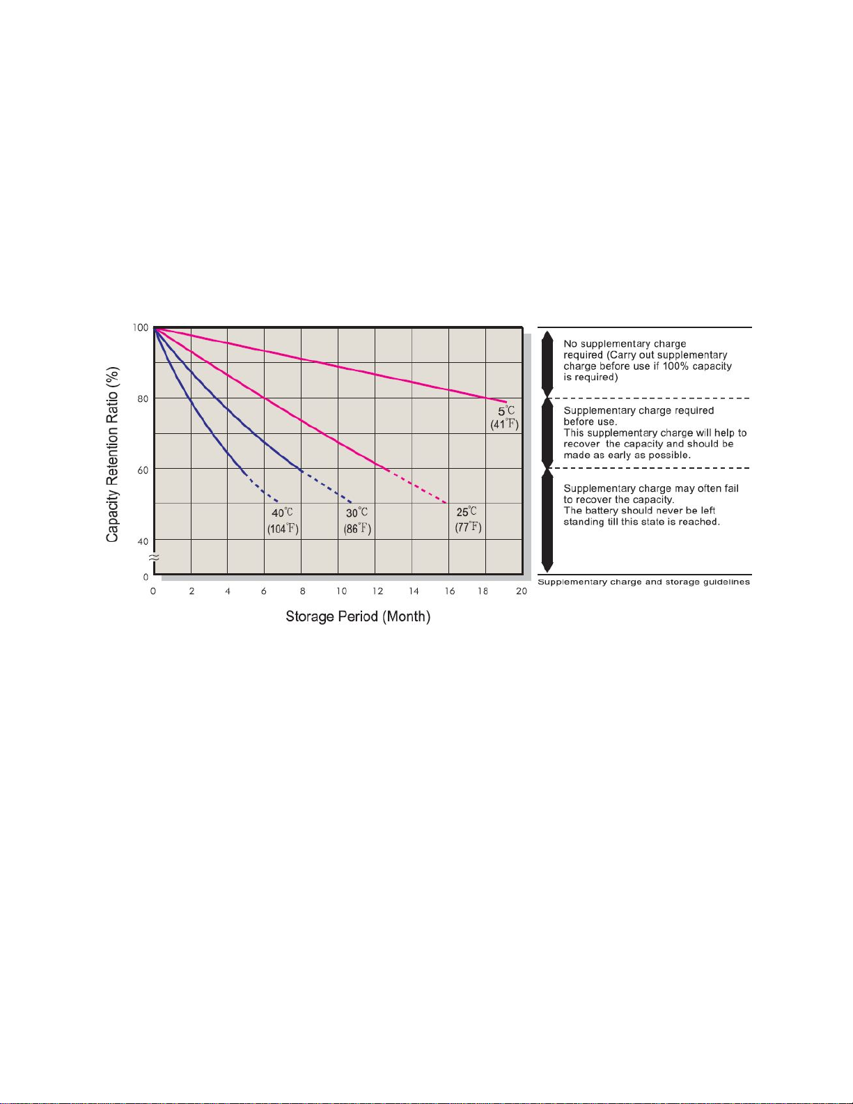
1.3 Battery Life....................................................................................................................... 2
2. Battery Cabinet Setup........................................................................................................... 3
2.1 Inspecting the Equipment................................................................................................. 3
2.2 Floor Loading................................................................................................................... 3
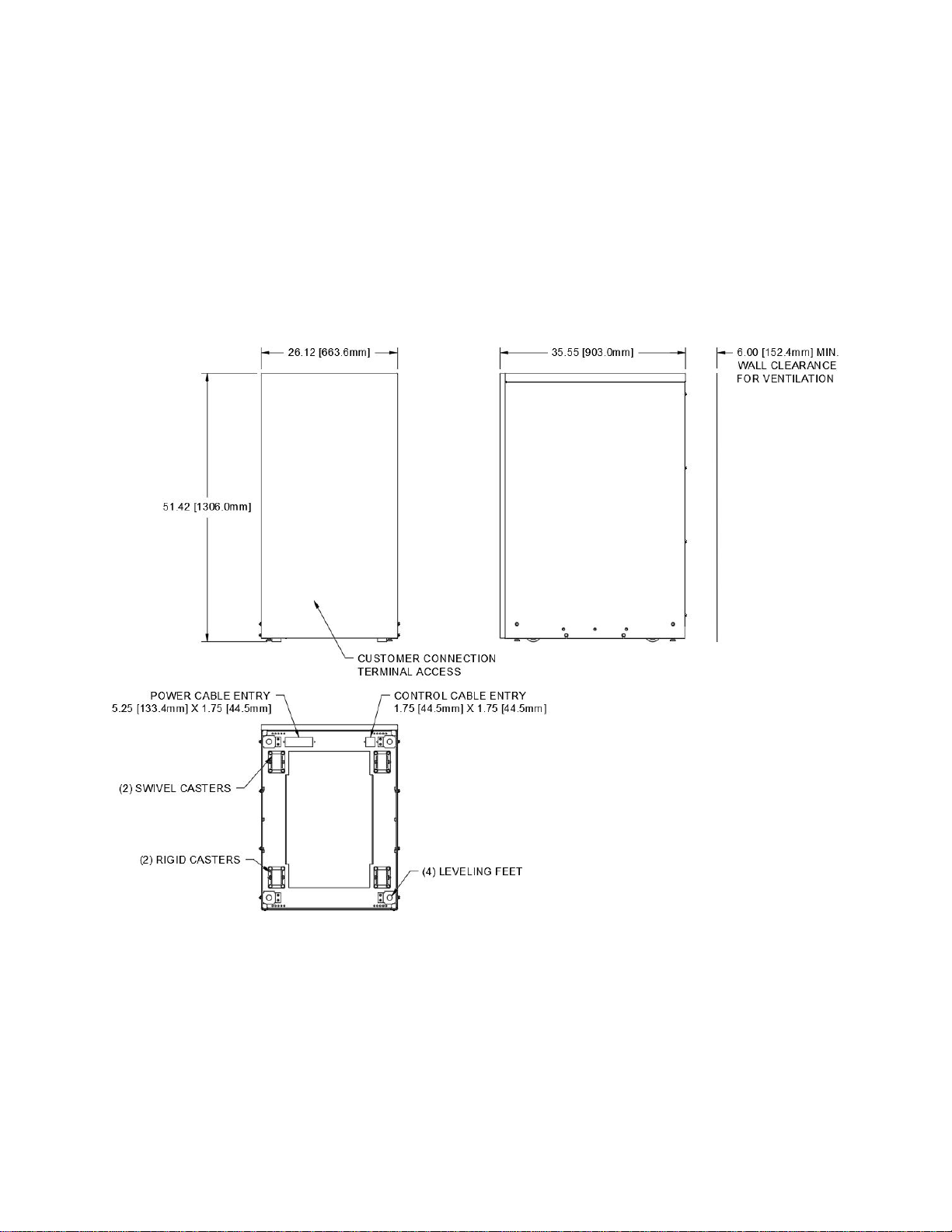
2.3 Clearances....................................................................................................................... 3
2.4 Unloading the Cabinet(s).................................................................................................. 4
2.5 Placing the Cabinet.......................................................................................................... 6
3. Electrical Installation .............................................................................................................. 7
3.1 Wiring Preparation............................................................................................................ 7
3.2 Connecting to the Extended Battery Cabinet...................................................................10
4. Circuit Breaker Interface .......................................................................................................12
5. Battery Removal, Installation, and Service............................................................................13
6. Maintenance .........................................................................................................................15
Table 1 - Symbols......................................................................................................................iii
Table 2 - Model Floor Loadings.................................................................................................. 3
Table 3 – Terminal Tightening Torques and Wires Sizes..........................................................11
Table 4 – Replacement Batteries and Operating Temperatures................................................15
Figure 1 - The Trident TRF Battery Cabinet............................................................................... 1
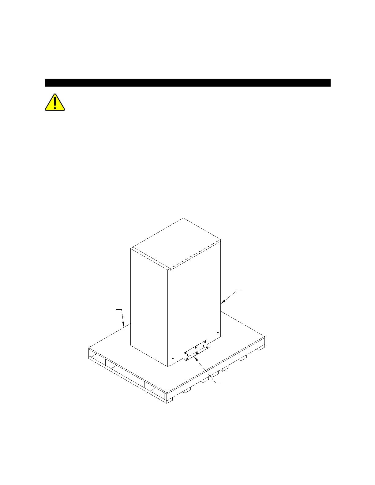
Figure 2 - Extended Run Time Battery Cabinet on Shipping Pallet............................................. 4
Figure 3 - Shipping Bracket........................................................................................................ 5
Figure 4 - Lifting Fork Area......................................................................................................... 6
Figure 5 – Leveling Foot Being Adjusted Down To Floor............................................................ 6
Figure 6 - Removing the UPS Front Panel................................................................................. 8
Figure 7 - Bottom View of Cabinet.............................................................................................. 9
Figure 8 – Circuit Breaker Panel................................................................................................ 9
Figure 9 - Connection Panel......................................................................................................10
Figure 10 – Communication Interface Board Connections ........................................................12
Figure 11 – Battery Bus Bar......................................................................................................13
Figure 12 – Battery Tray ...........................................................................................................14
Figure 13 – Cabinet Schematic.................................................................................................16

Page | 1
1 Layout
1.1 Introduction
The Extended Run Time Battery Cabinet is used in conjunction with the uninterruptible power
supplies (UPS) to prevent loss of valuable electronic information and minimize equipment
downtime. During brownouts, blackouts, and other power interruptions, batteries provide
emergency power to safeguard operation.
1.2 Layout
Figure 1shows the Battery Cabinet, which can be outfitted with one string of batteries.
Figure 1 - The Trident TRF Battery Cabinet

Page | 2
1.3 Battery Life
The batteries in your Dual-Lite UPS system were shipped from the factory fully charged. If you
plan to place the batteries in storage for any period of time prior to installation and startup then
the following precaution should be followed.
Batteries placed in storage will age. How fast they will age depends on the storage
temperature. The batteries are rated for storage over a temperature range of -15o C to 40o C (5o
F to 104o F). The amount of time the batteries may be stored without recharge varies greatly
with storage temperature. Please consult the following table. If the batteries are allowed to sit
in storage for an excessive period of time before recharging then they are subject to irreversible
damage.
Once the batteries are placed into service and fully charged, the useful life of the batteries will
be reduced if they are subjected to high temperatures. The operating temperature range of -15o
C to 40o C (5o F to 104o F) must not be exceeded for even short periods of time. Batteries
operating continuously at or near 40o C will experience a shorter useful life than batteries
operating continuously at 25o C. Battery life will be further shortened if the batteries are allowed
to fully discharge and then left in that condition for extended periods of time. As soon as the
load is removed from the battery it will continue to age at a higher rate than a fully charged
battery. The longer the battery remains discharged the greater the risk of irreversible damage.
Allowing the batteries to become damaged due to; a) operation or storage outside the
rated temperature range, b) storage for extended periods of time without recharge per
the table above, or c) sitting for a period of time in a discharged state will void the battery
warranty.

Page | 3
2. Battery Cabinet Setup
This SECTION describes:
Equipment inspection
Floor loading and clearances
Removing and replacing the cabinet panels
Unloading the cabinet(s)
2.1 Inspecting the Equipment
If any equipment has been damaged during shipment, keep the shipping and packing materials
for the carrier or place of purchase and file a claim for shipping damage. If you discover damage
after acceptance, file a claim for concealed damage.
To file a claim for shipping damage or concealed damage: 1) File with the carrier within 15 days
of receipt of the equipment, 2) Send a copy of the damage claim within 15 days to your service
representative.
2.2 Floor Loading
When planning the installation, consider the battery cabinet weight for floor loading. The
strength of the installation surface must be adequate for point and distributed loading. The
approximate weights are shown in the following table.
Table 2 - Model Floor Loadings
STANDARD MODEL FLOOR LOADING
Battery Size
Maximum Weight
Point Loading
90W 939 lbs (426 kg) 299 lb/in2(21 kg/cm2)
150W
1313 lbs (596 kg)
418 lb/in
2
(29 kg/cm
2
)
2.3 Clearances
The following clearances are recommended for the Extended Run Time Battery Cabinet.
From Front of Cabinet
36” (91.4 cm) working space
From Back of Cabinet
6” (15.2 cm)
From Side of Cabinet to UPS
Minimum 24” (61 cm)

Page | 4
Pallet
Shipping bracket - (1) this
side and opposite side
Forklift access
from rear
2.4 Unloading the Cabinet(s)
The following tools are required for unloading the cabinet(s):
Wrenches for 3/8” bolts
Forklift
The battery cabinets are heavy (see Table 2). Unloading the cabinets requires at least
two people to safely remove the cabinets from the pallet.
To remove the battery cabinet from the ship pallet:
1. Make sure the forklift is rated for the cabinet weight.
2. Remove all banding, wrapping, and foam protectors.
3. Remove and discard the six 3/8” bolts and washers securing the shipping brackets to the
cabinet (see
4. Figure 2 and Figure 3).
5. Remove and discard the six 3/8” lag bolts securing the shipping brackets to the pallet
and pull the brackets away from the cabinet.
Figure 2 - Extended Run Time Battery Cabinet on Shipping Pallet
CAUTION

Page | 5
Remove and discard
3/8" bolt and washers
(6) places
Remove and discard
3/8" bolt and washers
(6) places
Pull (2) shipping brackets
away from cabinet.
Remove and discard
3/8" lag bolts
(6) places
Figure 3 - Shipping Bracket
6. Remove the front cover (see Figure 6) before inserting the lifting forks.
7. Ensure that the four (4) leveling feet are raised so that they will not touch the floor when
the cabinet is placed on the floor.
8. Lift the cabinet with a forklift from the rear of the unit, one to two inches (1”-2” [2.5-5cm])
above the pallet (see Figure 4).
9. Slide the pallet completely away from the raised cabinet.
10. Slowly lower the cabinet to the floor or other appropriate flat surface.
WARNING
DO NOT ALLOW THE FORKLIFT TO MOVE WHILE THE CABINET IS RAISED,
ONLY MOVE THE CABINET VERTICALLY TO REMOVE THE PALLET FROM
UNDER THE CABINET.

Page | 6
Figure 4 - Lifting Fork Area
11. Reinstall the front cover.
12. Roll the cabinet to the desired location.
13. Do not move the cabinet to another location by forklift as the cabinets are heavy and
may fall. Do not tip the cabinet more than 15 degrees from vertical.
2.5 Placing the Cabinet
Once the cabinet has been rolled into position, remove the front panel to access the front
leveling feet by pulling the panel outward at the bottom of the unit until it unsnaps and then lift
up and off the cabinet (see Figure 6). Adjust the leveling feet as shown in
Figure 5.
Figure 5 – Leveling Foot Being Adjusted Down To Floor

Page | 7
3. Electrical Installation
The Extended Run Time Battery Cabinet has the following power connections:
TB1, 3 pole (positive, neutral, negative) terminal block and ground connection for battery
power input. This goes to the UPS or to the next battery cabinet closer to the UPS.
TB2, 3 pole (positive, neutral, negative) terminal block and ground connection for battery
power output. This goes to the input of the next battery cabinet in the set.
TB3, 3 pole (positive, neutral, negative) terminal block and ground connection for battery
power output. This goes to the input of the –N version battery cabinet from the first –B
version battery cabinet closest to the UPS.
WARNING
TB3 is energized at all times. Opening the circuit breakers does not remove
power from this terminal block.
DANGER
Only qualified service personnel (such as a licensed electrician) should perform
the UPS installation and initial startup. Risk of electrical shock.
3.1 Wiring Preparation
To begin wiring the UPS:
1. Verify that the electrical connections to the installation site have been properly installed.
2. A wall-mounted, user-supplied, readily-accessible disconnection device must be
incorporated in the battery input wiring unless at least one of the battery cabinets has
disconnect.
3. Wire the UPS per the User’s Manual.
4. Switch off utility power to the distribution point where the UPS is connected. Be
absolutely sure there is no power.
5. Removing and replacing the front panel:
Lift the panel up and off the cabinet.

Page | 8
To replace the panel:
Lower the shoulder screws at the top and bottom of the panel into the keyhole
slots on the cabinet.
Figure 6 - Removing the UPS Front Panel
6. If the optional circuit breaker is included, switch it to the “OFF” position.
7. Remove the inner front cover by removing the (10) ten screws mounting it to the
enclosure.
8. Conduit landing plates are located at the front bottom of the base to accommodate
bottom wire entry to the cabinet (see Figure 7). Remove plates and drill or punch hole
to fit conduit bushing with Greenlee punch or similar device. Make certain that the
bushing will be clear in the opening in the base. Mount bushing to plate and tighten to
manufacturer’s recommendations. Replace the plates and mount conduit.

Page | 9
POWER CABLE ENTRY
5.25 [133.4mm] X 1.75 [44.5mm]
(2) SWIVEL CASTERS
(2) RIGID CASTERS
(4) LEVELING FEET
4.40 [111.8mm]
16.34 [415.0mm]
2.44 [61.9mm]
CONTROL CABLE ENTRY
1.75 [44.5mm] X 1.75 [44.5mm REAR
Figure 7 - Bottom View of Cabinet
PRODUCTS CO.
R
U1
R3
R2
R1
Q1
J3
J2
J1
F1
D2
D1
BATTERY CIRCUIT BREAKERS
-B VERSIONS ONLY BATTERY FUSES BATTERY BREAKER
INTERFACE BOARD
CB1
F1 F2
WARNING!
TO REDUCE RISK OF FIRE,
REPLACE ONLY WITH SAME TYPE
AND RATING OF FUSE.
CB2
Figure 8 – Circuit Breaker Panel

Page | 10
3.2 Connecting to the Extended Battery Cabinet
To be performed by authorized service personnel:
1. Inspect battery trays for signs of damage. Verify that all terminal connections are sound.
The red and black “powerpole” connectors will be connected, but the blue and white
connectors on the wires joining the trays in the string should not be connected.
2. If possible, after connecting the loose “powerpole” connections (blue to blue, white to
white), use a voltmeter to verify that the battery string is above 408 VDC at the TB3
connector. If the voltage is low or the voltage varies significantly from string to string,
please consult Dual-Lite service.
Figure 9 - Connection Panel
3. The battery cabinet(s) to be installed must include the at least one –B version. The first
–B cabinet must have its input terminal block (TB1) wired directly to the UPS. To wire
additional battery cabinets, wire from TB2 of the first battery cabinet to TB1 of the
second –B battery cabinet. Repeat these steps for additional –B cabinets. Use wire
sized per local codes, #6 AWG 75° C copper wire minimum to #2/0 AWG maximum.
When a –N version cabinet is installed with a –B cabinet, the –B cabinet must have its
TB1 terminal block wired to the UPS or another –B cabinet. To wire from the –B cabinet
to the –N cabinet, wire from TB3 of the –B cabinet to TB1 of the –N cabinet. To wire
additional –N battery cabinets, wire from TB2 of the first –n battery cabinet to TB1 of the
second –N battery cabinet. Repeat these steps for additional -N cabinets.
There must be at least one –B cabinet among the battery cabinets. If it is desired to
create a battery system involving all –N version cabinets and a user provided disconnect
switch, contact Dual-Lite for requirements for the disconnect switch.
DANGER
TB3 is energized at all times. Opening the circuit breakers does not remove
power from this terminal block.
4. Connect the ground wire to the ¼-20 ground stud with a ring terminal or pressure lug by
removing and replacing the top nut and washers only with a 7/16” wrench.

Page | 11
5. Before working within the UPS cabinet, verify that the UPS has no power applied.
Before touching the Extended Run Time Battery connector in the UPS, verify that all
internal battery strings are disconnected (that is, verify that the blue and white
“powerpole” connectors are NOT mated). Refer to the UPS manual. Repeat procedures
3 and 4 to the UPS Extended Run Time Battery connector located in the lower left side
of the UPS. We recommend that the wires be marked as to which is positive (+) and
negative (-) to ensure that the wires are not accidentally crossed. See Figure 8and
Figure 9.
DANGER
Never connect the positive to the negative. Severe damage and injury could result.
Check polarity at the TB3 terminal block.
6. For –B cabinets, connect the Circuit Breaker Interface per Section 4. Circuit Breaker
Interface.
7. Mate the blue connections, blue to blue, and then the white connections, white to white.
See Figure 13. Repeat this procedure for the other battery cabinets, if present.
8. Reinstall the front inner panel on each battery cabinet using the screws provided.
9. After the internal batteries in the UPS are connected, reinstall any panels that were
removed and close the UPS doors. Refer to the UPS manual for guidance regarding this
procedure. After the UPS cabinet is closed, the battery cabinet breakers may be closed
and the outer front panels may be replaced on the battery cabinets.
Terminal blocks on the –N version cabinets are disconnected by unplugging the
“powerpole” connectors in all cabinets. This requires the removal of the inner panel by
authorized personnel only.
Table 3 – Terminal Tightening Torques and Wires Sizes
BATTERY INPUT/OUTPUT TERMINAL
TIGHTENING TORQUE
#2/0 - #6 AWG
120 inch-pounds
GROUND STUD TIGHTENING TORQUE
Extended Run Time Battery Cabinet
100 inch-pounds
UPS Cabinet
55 inch-pounds
kVA Rating
Minimum Input/Output
Wire Size
Minimum Ground
Wire Size
10 / 15
#6 AWG
#10 AWG
20
#4 AWG
#10 AWG
30
#2 AWG
#8 AWG
*Wire must be rated 75°C or higher. Use copper conductors only.

Page | 12
4. Circuit Breaker Interface
NOTE: Disregard this section if tripping the battery cabinet breakers via REPO activation
is not required.
Figure 9shows the location of the Battery Breaker Interface terminal block on the battery
cabinet.
NOTE: Wires to the Battery Breaker Interface terminal block TB4 must not enter the UPS
or battery cabinet through the same port as the input/output or battery power wires.
Figure 10 – Communication Interface Board Connections
To trip the battery circuit breakers via the REPO of the UPS, connect the battery cabinet
interface connector (TB4) to the UPS per Figure 10. If any additional battery cabinets are –N
versions, no other connections are needed. If a Dual-Lite maintenance bypass switch cabinet is
included, wire those connections instead per
Figure 5 of the Maintenance Bypass Switch User’s Manual.
WARNING
CAUTION: The Battery Breaker Interface Board is an electrostatic sensitive device. The
user should be grounded when connecting to this assembly.
CAUTION: If the battery cabinet circuit breakers trip or are opened, the internal batteries
of the UPS are still connected and providing power to the UPS. They also cause the
terminals of the TB1 and TB2 to be energized with hazardous voltage.

Page | 13
5. Battery Removal, Installation, and Service
The batteries must only be serviced by authorized service personnel. Always wear eye
protection and have eye wash near at hand. Never work on any connections that have not been
disconnected from all other sources of voltage. Parallel connected battery cabinets require that
all battery strings in all battery cabinets be disconnected before working within any particular
cabinet. Also, the UPS is usually equipped with internal batteries that must be disconnected
before service (refer to the UPS manual).
Before servicing batteries, the UPS should be turned off, power should be removed from the
UPS input, and all battery breakers and disconnect switches should be open. If a Maintenance
Bypass Switch (MBS) is present, power to the load can be maintained during service. Refer to
the instructions for the MBS to put the system in bypass mode before removing power from the
UPS.
Before any battery service is attempted, the batteries must be disconnected by unplugging the
cables to the battery trays. If it is necessary to remove the cables from the batteries, the
connections should be marked in a way that no confusion will exist when it is time to reconnect
the cables (see Figure 13). The batteries are mounted in slide out trays that permit access to
the battery to battery connections when the trays are withdrawn from the cabinet.
WARNING
To service the battery trays, they must be removed from the cabinet by a fork lift.
The 2 bus bars at the back of the tray, as shown in
Figure 11, for -150 cabinets or 3 busbars on the right of the tray for the -090
cabinets must be removed before servicing or replacing the batteries.
Figure 11 – Battery Bus Bar
If batteries are being replaced, only use the same manufacturer and battery type and rating as
the battery removed. When the bus bars connecting the batteries are removed, be careful to
avoid dropping bolts or shifting the bus bars so that they might short across adjacent battery
terminals. We recommend using a piece of electrical insulating paper (for example, “Nomex”)
as a temporary shield between the bus bars during service.

Page | 14
WARNING
It is very important that only one tray at a time be extended from the cabinet. If more
than one tray is extended, the cabinet can become unstable and topple over.
After each tray is installed or serviced, it must be fully inserted and secured using the supplied
threaded fasteners before attempting to install or service another tray.
If the trays are to be removed, always remove the highest tray first. The battery trays are very
heavy and it will be necessary to use a lifting device to support the trays as they are removed.
When the trays are to be reinstalled, use the procedure in the following paragraph.
The battery trays are very heavy and it will be necessary to use a lifting device to support the
trays as they are installed. Do not take away the external support until the extension limit tabs
on the upper sides of the battery tray are inserted past the notches on the upper edge of the
battery shelf (see Figure 12). Always install the lowest battery tray first. After it is inserted fully
into the support shelf, secure the tray with the supplied threaded fasteners. After all of the trays
are reinstalled and secured, reconnect the cables using the markings as a guide.
DANGER
Never connect the two cables from a battery tray or from a battery string (two trays)
together as severe damage will occur, resulting in fire and/or injury. Battery
connections should only be made by a person wearing eye protection. It is advised
that eye wash be available. If there are any doubts about the proper connections, do
not proceed.
Battery tray
Battery shelf
Notch
Extension limit tab
Cutaway side view of battery tray
batteries not shown for clarity
Tray mounting screw
Figure 12 – Battery Tray

Page | 15
6. Maintenance
The Extended Run Time Battery Cabinet is designed to be virtually user maintenance free,
requiring only the occasional wipe with a damp cloth or non-abrasive cleaner.
Spare kits are available for the Extended Run Time Battery Cabinet series, please contact Dual-
Lite service center for details.
For maximum availability of the UPS, the batteries should be replaced as part of a
comprehensive preventive maintenance program.
Table 4 – Replacement Batteries and Operating Temperatures
REPLACEMENT BATTERY
Cabinet Model
Manufacturer
Cat. Number
Qty Required
-090
China Storage Battery
HR1290W
36 Per String
-150
China Storage Battery
HRL12150W
36 Per String
RECOMMENDED REPLACEMENT INTERVALS
Batteries
2 to 5 years
Battery life is highly dependent on the ambient temperature and the number and depth of discharge
cycles. A discharged battery should be recharged as soon as possible. If the battery is left in a discharged
state, irreversible sulfation occurs, reducing the capacity (run-time) of the battery.
OPERATING TEMPERATURE
Recommended Range
15-25º C (59-77º F)
Maximum Range
10-40º C (50-104º F)
This product contains Value Regulated Sealed Acid Batteries. These batteries contain lead, a
neurotoxin, and sulfuric acid, a corrosive. Additionally, the energy stored in the batteries can
present a shock hazard and a burn hazard. Batteries should be serviced by trained personnel.
Appropriate safety precautions must be observed, including eye protection and skin protection.
Contact with electrolyte requires flushing with generous amounts of clean water. Seek medical
attention immediately following contact with electrolyte. Unwanted batteries must be recycled
and should never be discarded.
The functional lifetime of batteries is significantly affected by the temperature at which they are
stored and operated. Ideally, batteries should be used in a 70° F (21° C) environment. For
every 15° F (8.3° C) increase in temperature, the life expectancy of a battery will be halved.
Exposure to temperatures in excess of 90°F (32°C) should be limited to no more than 30 days
per year. Under no circumstances should the battery be exposed to temperatures over 104° F
(40° C) which can lead to thermal runaway, a condition that damages the battery. Thermal
runaway can cause batteries to swell. If the battery cases burst, the hazardous contents may
be exposed.
Maintaining proper ambient temperature usually requires installing the product in a temperature
controlled space. Equipment rooms without cooling systems do not generally maintain the
proper conditions for good battery life.
See Hubbell Lighting’s website for warranty details:
http://www.hubbelllighting.com/resources/warranty/
Table of contents