Hubbell PBX Series User manual

INSTALLATION, OPERATION, AND
MAINTENANCE MANUAL FOR
HYBRID ELECTRIC HEAT PUMP
WATER HEATER
ELECTRIC HEATER COMPANY
BASE MODEL “ PBX ”
2015

HUBBELL
ELECTRIC HEATER COMPANY
P.O. BOX 288
STRATFORD, CT 06615
PHONE: (203) 378-2659
FAX: (203) 378-3593
INTERNET: http://www.hubbellheaters.com/
-- IMPORTANT --
Always reference the full model number and serial number when calling the factory.
WARNING / CAUTION
1. Tank is to be completely filled with water and all air is to be vented before energizing.
Do not turn on water heater if cold water supply shut off valve is closed.
2. Due to the rigors of transportation, all connections should be checked for tightness
before heater is placed in operation.
3. Safety relief valve must be installed in tapping provided.
4. The refractory material used in heating elements may absorb some moisture during
transit, periods of storage, or when subjected to a humid environment. This moisture
absorption results in a cold insulation resistance of less than twenty(20) megohms. If this
heater has been subjected to the above condition, each heating element must be checked
for insulation resistance before energizing. A low megohm condition can be corrected by
removing the terminalhardware and baking the element in an oven at 350°F -700°F for
several hours or until the proper megohm reading is obtained.
5. KEEP AWAY FROM LIVE ELECTRICAL CIRCUITS.
Do not perform any maintenance, make any adjustments, or replace any components
inside the control panel with the high voltage power supply turned on. Under certain
circumstances, dangerous potentials may exist even when the power supply is off. To
avoid casualties, always turn the power supply safety switch to off, turn the charge or
ground the circuit before performing any maintenance or adjustment procedure.
6. The unit is designed to operate at pressure not more than 150 psi.
7. Generalized instructions and procedures cannot anticipate all situations. For this reason,
only qualified installers should perform the installations. A qualified installer is a person
who has licensed training and a working knowledge of the applicable codes regulation,
tools, equipment, and methods necessary for safe installation of an electric resistance
water heater. If questions regarding installation arise, check your local plumbing and
electrical inspectors for proper procedures and codes. If you cannot obtain the required
information, contact the company.
8. In the event of overheating, fire, flood, or physical damage, turn off all power to your
water heater. Do not power the heater until it been examined by a trained professional.
9. Do not store or use gasoline or other flammable vapors and liquids, such as adhesives
or paint thinner, in the vicinity of this water heater. If such flammable materials must
be used near the unit, open nearby doors and windows to allow for ventilation
2

Safety Information and Precautions:
Please read the following safety information before proceeding:
•Water temperature over 125°F can cause severe burns instantly or
death from scalds.
•Children, disabled and elderly are at the highest risk of being scalded.
•See instruction manual before setting temperature at the water heater.
•Feel water before bathing or showering.
•Temperature limiting valves are available, see manual.
The temperature of the water in the heater is regulated by an adjustable,
automatic, temperature control which uses surface mounted thermistors
located behind the jacket access panels. These automatic controls are set at the factory to
maintain a water temperature of 120°F. Although these controls are designed to industry
standards, they can fail to control temperature properly without any notice, and therefore
should be tested periodically for your protection.
To perform the test: Turn on the hot water faucet and measure the maximum temperature with
an accurate thermometer. If the temperature is above the safe limits for your circumstances
call a service technician to adjust or replace the control.
DANGER: IF YOU DISCOVER EXTREME HOT WATER COMING FROM THE
FAUCET, IMMEDIATELYSHUT OFFTHE ELECTRICITYATTHE MAIN SWITCH
AND CALL COMPETENT SERVICE PERSONNEL. ANY OVERHEATED WATER
HEATER IS A POTENTIAL HAZARD TO LIFE AND PROPERTY. DO NOT
OPERATE UNTIL THE SOURCE OF THE PROBLEM HAS BEEN DETERMINED
AND ELIMINATED.
SECTION
PAGE No.
Operating Principle, Specifications, and Performance
4
Installation
8
Controller Operation
9
Data Logger Configuration and Operation
18
Scheduled Maintenance
22
Troubleshooting
23
Servicing and Replacement of Parts
26
Warranty
29
3

OPERATING PRINCIPLE, SPECIFICATIONS, AND PERFORMANCE
How the Hubbell Heat Pump Water Heater Works
The Hubbell Model PBX Heat Pump Water Heater uses a small amount of electricity to
transfer heat from the air to water. In comparison, traditional electric water heaters use
resistive heating elements to directly heat the water. A benefit of a the heat pump water heater
is that it uses less than half the electricity of a traditional electric water heater to produce the
same amount of hot water and therefore the Hubbell Model PBX is significantly more energy
efficient compared to a conventional electric water heater.
In principle, a heat pumps works like a refrigerator in reverse. A refrigerator moves heat from
inside the refrigerator and transfers that heat energy to the surrounding room. A heat pump
water heater on the other hand pulls free and essentially unlimited heat from the surrounding
air and transfers that heat to the water stored in the tank.
The Hubbell Model PBX Heat Pump Water Heater can pull heat out of air as cool as 40°F,
and if it cannot provide enough heating capacity to meet demand, the water heater includes
back-up resistive heating elements to ensure the unit provides sufficient hot water. In addition,
the heat pump process of removing heat from the air and transferring it to the water results in
the exhaust of cooler dryer air, with as much as 0.4 gallons per hour of “free” dehumidification
provided by the heat pump while the unit is heating water.
Heat Pump Functions with Operational Diagram:
1. The built in fan draws room air into the heat pump
compartment and across an evaporator coil, and exhausts
cooler and slightly dryer (dehumidified) air.
2. The evaporator coil captures heat energy in the air and
transfers that energy to a specially formulated CFC free
refrigerant contained within the evaporator.
3. The refrigerant changes from a liquid to a gas as it gets
warmer.
4. The refrigerant, now as a warm gas, exits the evaporator
and passes into a compressor.
5. The warm gas is compressed, causing it to become a
superheated hot gas and then flows to the heat exchanger.
6. The heat exchanger transfers heat energy from the
superheated hot gas to the cold water from the tank.
7. The pump circulates cold water from the tank through the
heat exchanger resulting in a continuous transfer of heat
energy from the superheated gas to the water.
8. Hot water exits the heat exchanger and is stored in the
tank.
9. The superheated gas condenses back to a liquid and the
process is repeated.
4

Outline Dimensions
Model Specific Dimensional Data
Base Model
Number
Storage
Capacity
(Gallons)
Dimensions (Inches)
Shipping
Weight
(lbs.)
Overall
Diameter
“A”
Overall
Height
“B”
Floor to Relief
Valve & Hot
Water Outlet
“C”
Floor to Cold
Water Inlet
“D”
PBX40SL
40
28
49
26
9
270
PBX50SL
50
25
66
43
9
325
PBX65SL
65
28
63
40
9
365
PBX80SL
80
28
73 ½
50
9
440
PBX120SL
120
30
84
61
9
525
Options
•1 ½” Male NPT inlet and outlet water connections.
•Corrosion-Resistant (Copper-Alloy, Type 304L or Type 316L stainless steel) storage tank
for maximum life.
•ASME tank construction.
•Tank installed heat exchanger for use with solar or radiant heating systems.
•Alternate single and 3 phase voltages, alternate wattages or 50 Hz available.
•Condensate removal pump (120V plug-in) to remove and lift condensate to drain.
5

Specifications
Tank:
Hydrastone Cement Lined Steel
Hi-Limit:
190°F Manual Reset
Pressure Rating:
150 psi WP, 300 psi TP
First Hour Rating:
(Gallons)
Storage:
40, 50, 65, 80, 119 Gallons
PBX40SL
46
Orientation:
Vertical
PBX50SL
61
Voltages:
208-240 Volt AC
PBX65SL
70
Phase:
Single
PBX80SL
82
Frequency:
60 Hz
PBX120SL
120
Inlet Size:
¾” Female NPT
Standby Heat Loss:
(°F/hr)
Outlet Size:
¾” Male NPT
PBX40SL
0.45
Drain Size:
¾” GHT
PBX50SL
0.36
Condensate Size:
⅜” Tube
PBX65SL
0.35
Relief Valve Size:
¾” Female NPT
PBX80SL
0.28
Relief Valve Type:
T&P, 210°F, 150 psi
PBX120SL
0.28
Heat Pump:
Energy Factor:
2.33
Refrigerant:
R426A (CFC Free)
COP:
2.36
ODP:
0
Average Power Consumption:
GWP:
1349
High Fan:
680 Watts
Over Pressure Safety:
Manual Reset
Low Fan:
614 Watts
Field Chargeable:
No
Electric Elements:
Incoloy Sheathed
Ambient Air:
3800W @ 240V
Air Flow (High Fan):
450 CFM
Insulation:
3” Polyurethane Foam
Air Flow (Low Fan):
250 CFM
Sound Level:
62db Average @ 3 Feet
Air Filtration:
Washable / Removable
Warranty:
Temperature Range:
40-110°F
Tank:
10 Years
Thermostat Range:
50-160°F (°F or °C) ±3°F
Parts:
6 Years
Error Indication:
Visual and Audible
Approvals:
cULus, ENERGY STAR
Demand Response
Qualified
Capable:
Yes
Jacket:
High Impact Colorized
Child Lock Capable:
Yes
Composite
Color:
White with Black Trim
Electrical
Amperage Rating Chart (Amps)
Supply Voltage Total Maximum Amp Draw in Various Operating Modes
Economy Hybrid Electric Super
240V
2.6
15.8
15.8 (3800 Watts)
18.4
220V
2.8
14.5
14.5 (3200 Watts)
17.3
208V
3.0
13.7
13.7 (2850 Watts)
16.7
Overcurrent circuit protection rated 25 amp minimum is required. Reference local, state, and
national codes.
6

Performance
These units are designed to meet or exceed ANSI (American National Standards Institute)
requirements and have been tested according to D.O.E. test procedures and meet or exceed the
energy efficiency requirements of NAECA, ASHRAE standard 90, ICC Code and all state
energy efficiency performance criteria for energy consuming appliances.
Ambient Air Temperature (°F)
Energy Consumption Chart Annual Energy Consumption (EST)
Ambient Air
Temperature Energy
Factor (EF)
Coefficient of
Performance
(COP)
Annual Energy Consumption and Operating Cost in Various Operating Modes
Economy
Hybrid
Electric
Super
kW·hrs Operating
Cost $ kW·hrs Operating
Cost $
50°F 1.39 1.42 3159 $336 3159 $336 4671 $497 4368 $465
70°F 2.33 2.36 1884 $201 1884 $201 4671 $497 3851 $410
90°F 3.07 3.07 1430 $152 1430 $152 4671 $497 3527 $376
Energy Factor and Average Annual Operating Costs based on 2007 D.O.E. (Department of Energy) test
procedures. D.O.E. national average fuel rate electricity 10.65¢/kW·hr. Energy Factor (EF) based upon
heater operating in Hybrid mode.
Recover Rating Chart Continuous Recovery Rating (GPH)
Ambien
t Air
Temp
Continuous Recovery Rating (GPH) in Various Operating Modes
Economy Hybrid Electric Super
60°F ∆T 70°F ∆T 80°F ∆T 60°F ∆T 70°F ∆T 80°F ∆T 60°F ∆T 70°F ∆T 80°F ∆T 60°F ∆T 70°F ∆T
80°F
∆T
50°F
6.5 5.6 4.9 25.9 22.2 19.4 25.9 22.2 19.4 32.4 27.8 24.3
70°F 10.9 9.4 8.2 25.9 22.2 19.4 25.9 22.2 19.4 36.8 31.6 27.6
90°F 14.2 12.2 10.6 25.9 22.2 19.4 25.9 22.2 19.4 40.1 34.4 30.0
Continuous Recovery rating based upon 240V power supplied to heater and fan operating in high speed
mode. ∆T represents the °F temperature rise for hot water.
Heating Capacity Chart
Heating Capacity Chart (BTU/Hr)
Ambien
t Air
Temp
BTU/Hr Rating in Various Operating Modes
Economy Hybrid Electric Super
50°F
3,240
12,965
12,965
16,205
70°F
5,400
12,965
12,965
18,365
90°F
7,020
12,965
12,965
19,985
Heating Capacity based upon 240V power supplied to heater and fan operating in high speed mode.
7

INSTALLATION
WARNING / CAUTION
DO NOT TURN ON THE ELECTRIC POWER SUPPLY to this equipment until heater is
completely filled with water and all air has been released. If the heater is NOT filled with water
when the power is turned on, the heating elements will burn out.
For protection against excessive pressures and temperatures, local codes require the
installation of a temperature-and-pressure (T&P) relief valve certified by a nationally
recognized laboratory that maintains periodic inspection of production of listed equipment of
materials, as meeting the requirements for Relief Valves and Automatic Gas Shutoff for Hot
Water Supply Systems, ANSI Z21.22. THE CUSTOMER IS RESPONSIBLE TO PROTECT
PROPERTY AND PERSONNEL FROM HARM WHEN THE VALVE FUNCTIONS.
All water heaters havea risk of leakage at some unpredictable time. ITIS THE CUSTOMER'S
RESPONSIBILITY TO PROVIDE A CATCH PAN OR OTHER ADEQUATE MEANS, SO
THAT THE RESULTANT FLOW OF WATER WILL NOT DAMAGE FURNISHINGS OR
PROPERTY.
Water Heater Placement
1. Place the heater on a solid foundation in a clean, dry location nearest to the point of
most frequent hot water use. If the heater is to be raised off the floor, the entire bottom
of the heater should be supported by a solid surface.
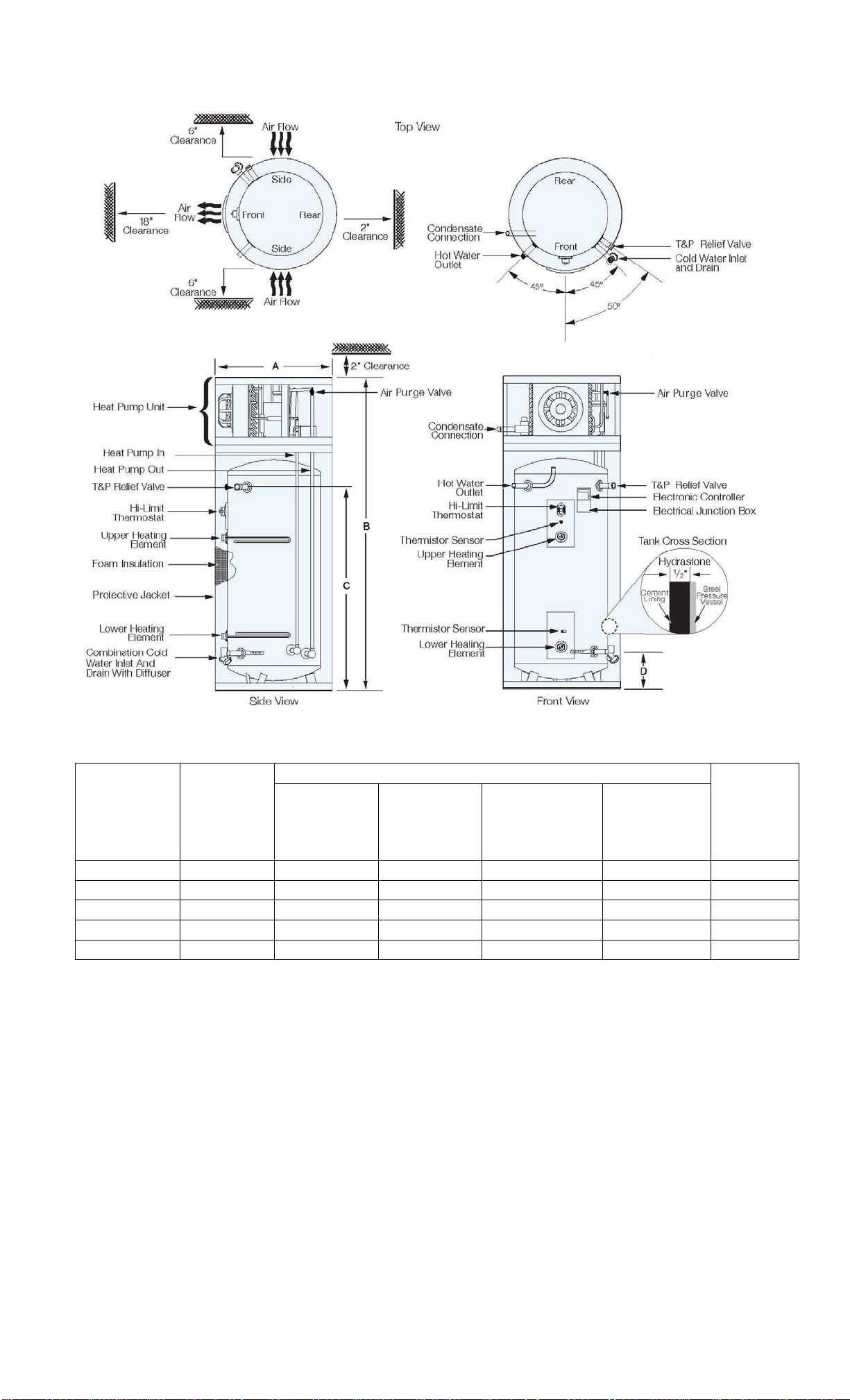
2. The water heater must be installed with the minimum clearances as shown on page 5.
3. Do not install in an area where flammable liquids or combustible vapors are present.
4. The water heater should be protected from freezing and waterlines insulated to reduce
energy and water waste.
5. The space that the water heater is installed must be no less than 10’ x 10’ x 7’ high
(700 cubic feet). If a smaller space is used, there must be louvers installed in the space
that will allow for 450 CFM air flow.
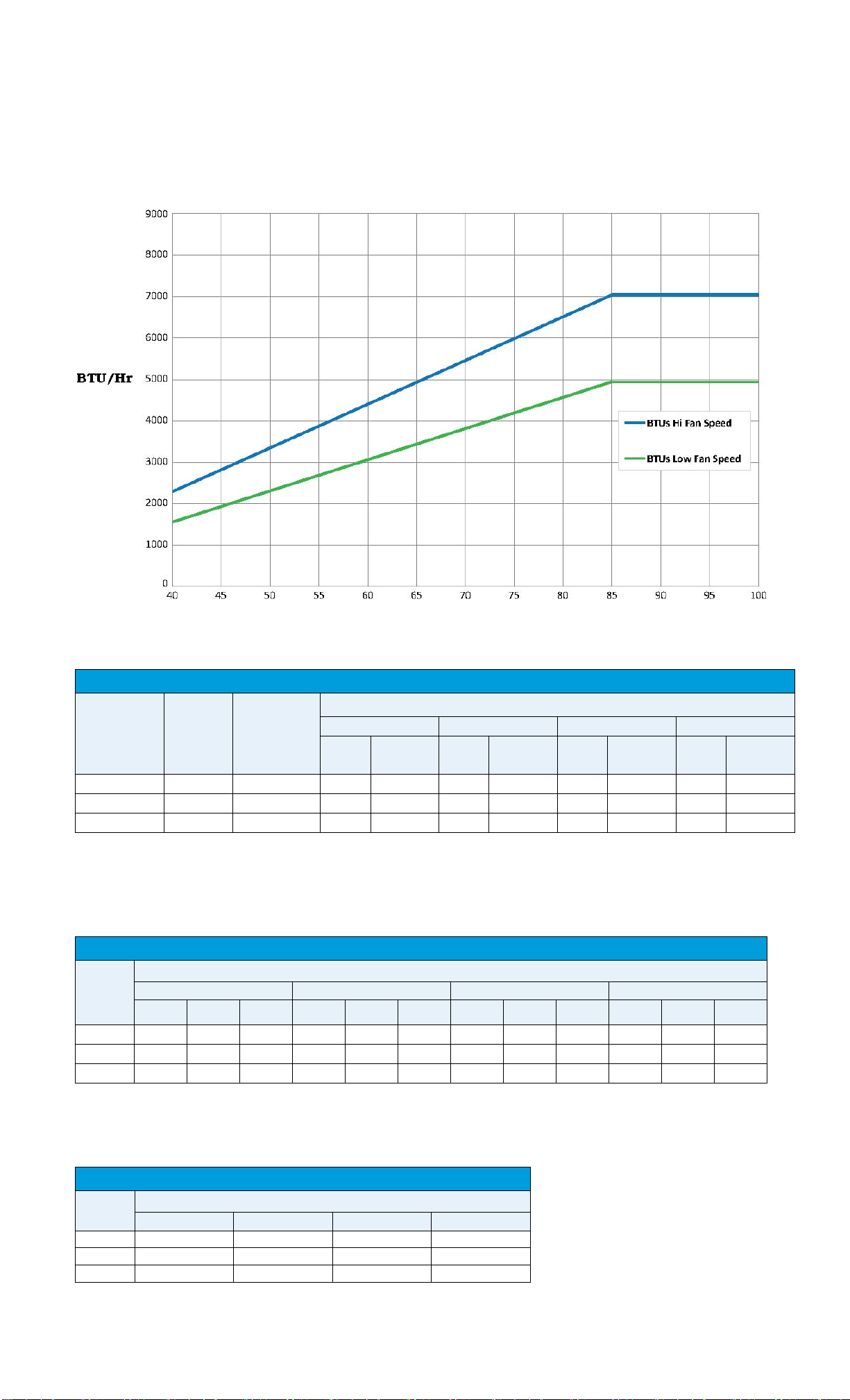
6. The installation location must not be cooler than 40°F. Locations with warmer
ambient air (ex. furnace rooms) are more advantageous as they provide abundant
“free” heat.
7. The heat pump dehumidifies the air and as a result produces condensate which must be
piped to a drain or outdoors.
Piping Installation
NOTE: The most effective means for preventing deterioration from accelerated corrosion
due to galvanic and stray current is the installation of dielectric fittings/unions. The installation
of these fittings is the responsibility of the installing contractor.
1. Connect the cold water inlet and hot water outlet to the appropriate connections as
shown; refer to the drawing for location and sizes.
NOTE: Certain models are supplied with a flow measuring device (flowmeter) and
temperature measuring device (thermistor) to be installed on the cold water supply
side. These items are shipped pre-wired into the unit and stored in the heat pump
compartment. The flowmeter should be installed in-line with the cold water supply
piping with the arrow pointing toward the water heater. The thermistor should be
secured to the outside of the cold water piping and covered with insulation.
2. Install the combination temperature and pressure safety relief valve in the tapping
provided. Note that this is required by law for safety considerations.
3. Install a relief valve overflow pipe to a nearby floor drain. CAUTION: No valve of
any type should be installed between the relief valve and tank or in the drain line.
8

Filling the Water Heater
1. Completely close the drain valve.
2. Open the highest hot water faucet to allow all air to escape from piping.
3. Open the valve to the cold water inlet and allow the heater and piping system to
completely fill, as indicated by a steady flow of water from the open faucet.
4. Close the faucets.
5. Lift the top cover of the heat pump unit.
6. Carefully open the Air Purge Valve at the top of the heat pump unit to let air escape.
See the Outline Dimensions illustration for the location.
7. Fully tighten Air Purge Valve.
Electrical Installation
1. Enter junction box with properly sized feeder leads. Note that overcurrent circuit
protection is required. For the standard model the overcurrent protection must be rated
25 amp minimum.
2. Connect these power leads to wires enclosed in junction box with wire nuts.
3. All other electrical connections are made at the factory; therefore, no other electrical
connections are necessary.
Final Checks
1. Check all connections for tightness.
2. Ensure that all the above steps are completed.
3. After the water is heated for the first time, monitor the water temperature as described
in the Scheduled Maintenance section.
CONTROLLER OPERATION
About the Controller
The Hubbell Heat Pump Water Heater Controller provides the user with the ability to control
and customize the operation of their heat pump water heater. The 4-digit display shows the
current status of the water heater, and can display useful information such as current
temperature conditions inside the tank, error notifications, and more. It allows basic
customization, such as mode and temperature set point, as well as more advanced options,
such as temperature differential, and display options. Once the setup is complete the water
heater is automatic in operation and will maintain a full tank of water at the temperature setting
of the controller.
Powering up your Heat Pump Water Heater for the first time
When the unit is first powered up, the default home screen is shown, see diagram below. This
screen consists of two alternating displays; one shows the current mode (e.g., hibr), and the
other shows the temperature set point (e.g., S120). These displays will switch every 5 seconds.
By default, the Hubbell Hot Water Heat Pump comes programmed with a temperature
setpoint of 120°F and set to hybrid mode (“hibr”).
The Home Screen
The home screen provides a quick reference to the current status of the water heater and can
be modified to fit the user’s preference. If desired, the temperature readouts can be displayed
in Celsius (see “Changing the Temperature Scale”) and the user has the option to display
9

either the temperature set point, denoted by a capital “S” preceding the set point, or the current
temperature conditions inside the tank, denoted by “t” and “b” preceding the top and bottom
temperatures, respectively (see “Changing the Home Screen”).
If an error condition is detected, the error code is displayed until the error condition is resolved.
There are several error conditions which may result in this behavior (see “Maintenance Alerts
and Procedures”).
As shown in the above diagram, the home screen also has two indicators; power and cool
down. The power indicator denotes whether active heating of the water is taking place. If the
power indicator light is not visible, the water in the tank has reached the desired temperature,
and thus no active heating is taking place. A blinking power indicator light means that the unit
has not yet reached the temperature set point, and that current is being drawn to power the
heating elements. A solid power indicator light means that the unit is calling for power, but is
not detecting the proper amp draw to the elements. This may indicate a problem with the
elements or that only the heat pump is running (normal for Hybrid and Economy modes). Set
the tank to Electric or Super mode to check operation of both elements.
When the compressor is running, pressure builds up within the heat pump module. The cool
down indicator shows whether or not the heat pump has had sufficient time to allow the
pressure within the system to stabilize. The duration of this cool down period is 10 minutes
and starts from the time when the compressor turns off. If the cool down indicator light is not
visible, either the cool down period is complete, or the unit does not currently require the use
of the compressor. A solid cool down indicator light indicates that the unit requires the use of
the compressor, and is currently within the cool down period.
Button Overlay
The button overlay provides the user with a means to alter the configuration settings and
control the operation of the water heater. A brief description of the basic functionality of each
button is provided below. Detailed descriptions of how to use these buttons to perform certain
functions is provided throughout this manual.
Standby: Used for taking the water heater in and out of standby mode. When the
unit is in standby, “STBY” will be displayed. This is not considered OFF
because the tank will come on at very low temperatures to prevent freezing.
Also serves as an execute button in certain menus.
Mode: Used for changing modes. Serves as a cancel button in certain menus.
Used for navigating the options menu.
Up: Used for increasing numeric settings. Also scrolls up when changing
options. Can be held for auto scroll.
Down: Used for decreasing numeric settings. Also scrolls down when changing
options. Can be held for auto scroll.
Away: Used for entering / exiting vacation override. Also used to set / unset
child lock.
Max Heat: Used for entering / exiting max heat override.
Fan Off: Used for entering / exiting fan off and fan speed overrides.
Operating Modes
The Hubbell Heat Pump Water Heater is equipped with four operating modes and four
temporary settings. A brief overview of each mode and setting is listed below:
10

(Economy):
Economy mode allows only the heat pump portion of the unit to operate; the electric heating
elements will not operate in this mode. This is the most efficient mode, but may not meet high
demand situations.
(Hybrid):
Hybrid mode makes efficient use of the electric heating elements. In Hybrid mode, the heat
pump provides the vast majority of the heating capacity. The top electric element will be
automatically switched on only when necessary to meet high demand situations.
(Electric):
Electric Mode disables the heat pump unit, allowing only the electric heating elements to heat
the water in the tank.
(Super):
Super mode allows either of the electric elements as well as the heat pump to function
simultaneously, providing the fastest recovery option for the unit. This is the least efficient
mode, but provides the fastest heating rate high demand situations.
(Vacation Override):
Vacation mode deactivates the water heater for extended periods of time by overriding the
current mode the water heater is set to. This is useful for saving energy when the water heater
will not be used for a period of several days. Using only the heat pump, the unit will maintain
a water temperature of 50°F to prevent freezing.
(Fan Off Override):
The Fan Off setting allows the user to temporarily stop the heat pump portion from operating
for a specified number of hours. This is useful if the water heater is located in a populated part
of a building, and the user wishes to temporarily eliminate any noise or airflow created by the
heat pump unit.
or (Fan Speed Override):
The Fan Off button can also be used to temporarily override the current fan speed setting. This
is useful for temporarily reducing, but not eliminating, any noise created by the heat pump
unit.
(Max Heat Override):
The Max Heat setting will override the heater’s current mode setting and temporarily change
to Super Mode, which will activate one of the electric heating elements as well as the heat
pump unit for a set period of time. This is useful if the user is expecting high demand hot water
usage for a specified number of hours.
Changing the Mode
To display the current mode,from the home screen, press the button once. This will display
the current mode the water heater is operating on for 10 seconds. This feature is useful if the
home screen is displaying an error condition. Allow the display to timeout, or press any button
other than the button to return to the home screen.
To switch between modes, from the home screen, press the button once. This displays the
current mode. Before 10 seconds elapses, press the button again. The display will show a
11

flashing “Econ” (economy). If this is the desired mode, either allow the display to timeout by
not pressing any buttons for 5 seconds or press the button to set the mode. If this is not the
desired mode, within 5 seconds continue to press the button until the desired mode is
selected (flashing). Press the button or allow the 5 second timeout to elapse to set the
mode.
Note: To cancel out of the mode select menu without changing the mode, press any button
other than the or buttons.
To activate vacation override, press the button on the controller. The display will show
“A-07,” indicating the default vacation length of 7 days. The minimum vacation length is 2
days and the maximum is indefinite. Use the or buttons to adjust the desired length of
time to use vacation mode. To set the water heater to vacation mode for an indefinite period,
use the or buttons to adjust the display until “AOFF” is visible.
Once the desired time period is set, press the button or allow the 5 second timeout to
elapse. The water heater will now be in Vacation mode. While in Vacation mode, the display
will alternate between “A-##”, where “##” is the number of days remaining in the vacation
mode period and “S.050” to indicate the maintained minimum temperature of 50°F. If the
water heater was set to vacation for an indefinite period, the display will read “OFF”, but the
tank will in fact maintain the 50°F minimum temperature.
The water heater will exit vacation mode automatically one day before the specified time
period has elapsed. It is designed this way such that when the user returns from being away,
hot water will be available. To manually cancel or end Vacation mode, press the button
once. The display should now alternate between “S.###” (the previous temperature setpoint)
and the mode the unit was set to prior to the start of Vacation mode (e.g., “hibr”). If the water
heater has been placed in vacation mode for an indefinite period of time (“AOFF”), the unit
will have to be manually activated. To do this, press the button.
12

Note: Use the or buttons to modify the setting or value on any screen designated as an
“edit mode” display.
To activate the Max Heat override,press the button on the controller. The display should
show “H-05,” indicating the default time setting of 5 hours. The minimum duration for this
override is 1 hour and the maximum is 99 hours. To adjust the Max Heat duration, use the
or buttons on the controller until the display indicates the desired amount of time in hours
(e.g., “H-10” for a 10 hour period of Max Heat).
Once the desired time has been set, begin the Max Heat feature either by allowing the screen
to time out after 5 seconds, or by pressing the button. While the Max Heat feature is
engaged, the display will alternate between “S.###,” where “###” is the temperature setting
for the unit (e.g., “S.120” for a setting of 120 degrees) and “H-##,” where “##” is the number
of hours remaining in the Max Heat session.
The Max Heat feature will automatically turn off after the specified number of hours has
elapsed. To end the session prematurely, press the button once. The display should now
alternate between the unit’s temperature setting (e.g., “S.120”) and the unit mode in use prior
to Max Heat, (e.g., “hibr”).
To activate the Fan Off or Fan Speed overrides,from the home screen, press the button on
the controller. The display will show “FSPd”, this represents the fan speed override. Press the
button or wait 5 seconds to continue to adjust the Fan Speed override duration or within 5
seconds, press the button again, and the unit will display “FOFF” on the screen, this
represents the fan off override. Once “FOFF” is selected, either wait 5 seconds or press the
button to adjust the duration of this override.
To adjust the fan override duration, the display will show “L-04” for low speed override (if
the fan speed is currently set to high speed), “h-04” for high speed override (if the fan speed
is currently set to low speed), or “F-04” for fan off override, as applicable, with “04” indicating
the default time setting for this feature as 4 hours. To adjust the duration, use the or
buttons on the controller until the display indicates the desired amount of time in hours (e.g.,
“F-10” for a 10 hour period of Fan Off).
Once the desired time has been set, to begin any fan override features, press the button or
wait 5 seconds to allow the screen to time. While the fan override feature is engaged, the
display will alternate between “S.###,” where “###” is the temperature setting for the unit
(e.g. “S.120” for a setting of 120 degrees) and “L-##”, “h-##”, or “F-##,” where “##” is the
number of hours remaining in the fan override session.
The Fan Off and Fan Speed feature will automatically turn off after the specified number of
hours has elapsed. To end the session prematurely, press the button once. The display
should now alternate between the unit’s temperature setting (e.g., “S.120”) and the mode in
use prior to engaging the fan override, (e.g., “hibr” for Hybrid mode).
13

Child Lock
Child Lock is essentially a button locking mechanism. If the user wishes, he or she may set
the child lock, which will disrupt any future attempt to change modes, change the set point,
etc. The user will be locked out of performing any function on the device until the child lock
is released.
To activate the Child Lock feature, press and hold the button until “chLd” is displayed
on the screen. The controller is now locked.
To deactivate the child lock, press and hold the button until “un” is displayed. You will
be returned to the home screen.
Temperature Setpoint
The temperature setpoint represents the desired approximate temperature of the water inside
the heat pump water heater. The setpoint may be adjusted to your liking as high as 160°F
degrees or low as 50°F, these are pre-defined temperature limits to prevent boiling and
freezing water in the unit and surrounding piping. Standby mode lowers setpoint to 50°F.
To change the temperature set point for hot water output, from the home screen, press the
AND buttons on the controller. The setpoint temperature will flash quickly on the
display. The temperature is adjusted up or down as the or buttons are pressed.
Pressing and holding the or will allow fast scrolling through the temperatures. Once
the desired temperature setting has been reached, press the AND buttons to save the
new setpoint. The setpoint will also be saved about 5 seconds after single button presses (not
after fast scrolling). The display will now alternate between the current mode setting (e.g.,
“hibr”) and the newly set temperature (e.g., “S.116”).
14

Controller Options and Settings
The Vaughn Heat Pump Water Heater is equipped with various customizable options and settings. A
brief overview of each option / setting is listed below:
To access the options menu,from the home screen, press and hold the button until the
display reads “FLtr”, this is the first selection in the options menu.
To navigate the options menu,if “FLtr” is not the desired option, continue to press the
button to cycle through the available options until the desired option is displayed. When the
option to be changed is displayed, press the or buttons to enter the edit mode. The edit
mode is active when the display is flashing and the option may be altered by pressing the
or buttons until the desired choice is displayed. To set the change, let the display timeout
after 5 seconds, press the button, or press the button. The change will be made and the
controller will return the user to the options menu.
Filter
A display alternating between “Err” (error) and “FLtr” indicates that the filter needs to be
cleaned. The error will have to be cleared manually, using this menu, after the filter has been
cleaned.
To clear the filter warning, in the edit mode press the or buttons until “cLr” is displayed
(“no” will cancel this operation). To finish clearing the warning, let the display timeout after
5 seconds, press the button, or press the button.
Fan Speed
The fan speed option gives the user the ability to adjust the fan speed between two levels, high
and low. While it is recommended to keep the fan speed on high for best efficiency, it can be
changed to low for noise and air flow reduction purposes.
To change the fan speed, in the edit mode press the or buttons to alternate between
high speed, “Hi”, or low speed, “Lo”. To set the change, let the display timeout after 5
seconds, press the button, or press the button.
Top Differential
Bottom Differential
A temperature differential represents how far the water temperature can fall before the water
heater must call for heat again. For example, if the setpoint is 120°F and the differential is
10°F, then after satisfying at 120°F, the water temperature must fall to 110°F before the
water heater will call for heat.
The top differential controls the temperature differential in the upper section of the water
heater. The top differential can be adjusted between 15 and 30°F. Typically, the top
differential is larger than the bottom differential.
The bottom differential controls the temperature differential in the lower section of the water
heater. The bottom differential can be adjusted between 5 and 20°F. Typically, the bottom
differential is smaller than the top differential.
To change the top or bottom differential, in the edit mode press the or buttons to the
desired differential. To set the change, let the display timeout after 5 seconds, press the
button, or press the button.
15

Buzzer
The buzzer is programmed to sound every 30 seconds whenever a critical error has been
detected. It is designed to attract the attention of the user, and it is highly recommended that
the user leave this buzzer on. However, this option allows the user to turn the buzzer off if
desired.
To turn the buzzer on or off, in the edit mode press the or buttons to alternate
between buzzer on, “bOn”, or buzzer off, “bOFF”. To set the change, let the display timeout
after 5 seconds, press the button, or press the button.
Display
By default, the home screen will show the set point (designated by an ‘S’ preceding the set
point). The display option provides the ability to change the temperature on the home screen
to show the measured water temperature inside the tank for both the upper and lower
sections. If this option is selected, the home screen will cycle the display to show the current
mode for 5 seconds, followed by the top temperature (designated by a ‘t’ preceding the
measurement) for 5 seconds, followed by the bottom temperature (designated by a ‘b’
preceding the measurement) for 5 seconds.
To change the home display mode, in the edit mode press the or buttons to alternate
between display setpoint, “diSS”, or display water temperature, “diSt”. To set the change, let
the display timeout after 5 seconds, press the button, or press the button. When set to
“diSt”, if the heat pump or lower heating element is actively heating, the power indicator
will blink when “b” is displayed, if the upper heating element is actively heating, the power
indicator will blink when “t” is displayed.
Defaults
Enabling this option will reconfigure the controller to factory defaults. The factory defaults
are shown below.
Mode: Hybrid
Top Differential: 30
Bottom Differential: 10
Fan Speed: High
Display: Show Set Point
Degrees: Fahrenheit
Buzzer: On
To set the unit back to factory defaults, in the edit mode press the or buttons to
alternate between cancelling the operation, “no”, or resetting to default, “YES”. To set the
change, let the display timeout after 5 seconds, press the button, or press the button
Degrees
The degrees option provides the user with the ability to switch between standard and metric
temperature readings. The “dEgF” choice will set the temperatures to be displayed in
Fahrenheit, and the “dEgC” choice will set the temperatures to be displayed in Celsius.
To change the display units, in the edit mode press the or buttons to alternate
between degrees Fahrenheit, “dEgF”, or degrees Celsius, “dEgC”. To set the change, let the
display timeout after 5 seconds, press the button, or press the button
16

Prime
Press the or buttons to select ON or OFF. Activating this feature will turn on just the
water pump to help it self prime. Pri will show on the display in place of the mode. Use this
feature for about 2 minutes if a pressure error occurs after installation or after the tank is
drained. Prime is automatically activated for two minutes upon power-up if the power was
off to the control for two days or more.
Settings Overview
17

DATA LOGGER CONFIGURATION AND OPERATION (optional)
About the Data Logger
The Data Logger provides the ability to interfaceremotely with your Heat Pump Water Heater.
Several tasks can be performed using this device, such as performing software updates, and
data logging. Primarily this device is used for gathering information regarding the current
operation of the Heat Pump Water Heater. It is constantly storing relevant information to
memory, such as current temperature conditions inside the tank, user settings, and energy
usage. This data can be accessed by the factory to help troubleshoot any problems, or to simply
check on the conditions of the unit.
Connecting the Data Logger
The other Data Logger connection is made by inserting the USB style connector into the
USB style port on the left side of the electronic controller. These are not USB compatible
connections. The Data Logger can be mounted on top of the tank with the supplied Velcro
pieces.
About the LED Indicator
An LED indicator located inside the data logger is used to diagnose the configuration of the
device and the status of the connection between the Data Logger and the factory servers.
•Red LED on but not blinking: The device is in default configuration, and has established
an Ad-Hoc network.
•Red LED blinking once per second: The device is attempting tolink to a user’s network.
•Green LED on but not blinking: The device has successfully linked to a user’s network.
•Green LED blinking once per second: The device is communicating with the factory
servers.
Configuring the Data Logger
When the Data Logger is first powered, it needs to be configured to link into the user’s wireless
network. This will allow the Data Logger to establish a connection with the factory servers,
unlocking the full capability of the device. The following steps describe the connection
procedure:
1. Ensure that the Data Logger is powered, and that the LED indicator is flashing red two
times per second. This means that the device is setup in its default configuration, and
has established its own Ad-Hoc network called “WaterHeater”.
-If the LED is flashing red only once per second, wait one minute. The LEDshould
go blank for a few seconds, and then begin flashing again. The device may repeat
this step, but will eventually return to default configuration, flashing red twice
per second.
-If the LED is solid flashing orange or green, the device is already configured, and
this setup process may be skipped.
2. With a PC, Laptop, or WiFi enabled device, scan for nearby wireless networks.
3. Connect to the non-secured network called “WaterHeater”.
18

4. Once connected, open an internet browser (Safari, Internet Explorer, Firefox, etc) and
navigate to “169.254.1.1”. The device setup overview page will be shown.
5. Click on “Configure Network”. The device configuration page will be shown.
6. For networks with a broadcasted SSID, continue to step 7. For networks with a hidden
SSID, or if the user wishes to enter the network information manually, skip to step 11.
7. Click on “Scan for Wireless Networks”, and wait a few seconds. The webpage should
now display information (SSID, signal strength, security-enabled) pertaining to the
available wireless networks in the vicinity of the Heat Pump Water Heater.
-If the scan does not return any results, either the Wireless AP (i.e. router) is too
far away from the device, or is incompatible with the Data Logger.
8. Select which network you would like to connect the device to by clicking on it.
9. If necessary, enter the security key associated with the network, and press “OK”.
10.Skip to step 13.
11.Click on “Other Network”.
19

12.Enter the information (SSID, security type, and security key) as required into the form
and press the “Join” button.
13.The following screen should be displayed, showing information regarding the previous
network configuration, and the current network configuration.
14.The Data Logger is now configured. Ensure that the configuration is correctby checking
the LED on the device. If it is flashing orange or green, then the device is properly
configured and connected to your network. If it is blinking red, the network parameters
entered may be incorrect, and if so, please return to step 1 to repeat this process.
If problems are encountered during the WiFi connection process, the following list of tips for
setting up routers for 802.11b use describes the settings for most typical access point (AP)
configurable parameters to enable compatibility with Microchip MRF24WB0Mx devices:
1. DHCP Settings - For DHCP on LAN side (where AP is DHCP server), set Router to
Enable DHCP server. Set Client Lease time to be longer than the typical off time of the
station to ensure that the IP address provided doesn’t change each time the station is
powered up. If an option for Always Broadcast is present for DHCP setup (broadcasts
all DHCP responses to all clients), it should be disabled.
2. Data Rate Settings - Ensure that service rates include 802.11b. 802.11g or 802.11n
only rates (green field) should be avoided, but mixed settings are usually acceptable. If
a Basic Rate setting is defined, it should be set to 1 and 2MBPS only.
3. SSID Broadcast - Should typically be enabled so that the AP sends beacon frames
containing theSSID. If disabled, ensure that Microchip Stack is set for Active Scanning.
4. Channel Selection - For debug purposes, it is typical to use a fixed channel instead of
Auto Channel Selection. If a fixed channel has been selected for the MRF24 Station,
select the corresponding channel (channels 1, 6, or 11) for the AP.
5. Multicast Passthrough - If using multicast features (ZeroConfig for instance) ensure
that the Router is configured to enable forwarding of Multicast packets.
6. Beacon Interval - Set the value for the time interval between AP beacons, typical is
100msec. For lower power, this can be set to a smaller value, say 30mS, if the DTIM
interval is correspondingly increased.
20
This manual suits for next models
5
Table of contents
Popular Heat Pump manuals by other brands

Gecko
Gecko in.temp Series Tech book

Lochinvar
Lochinvar Amicus LAHP302WW Installation, Commissioning, User and Maintenance Instructions

Daikin
Daikin EGSQH10S18AA9W installation manual

EMI
EMI DWPH365 (WHP36-SHC36) specification

Carrier
Carrier OG-HPR410GEN-03 owner's manual

Mitsubishi Electric
Mitsubishi Electric PUZ-WM50VHA Service manual

iDM
iDM TERRA SW Series Technical documentation, service manual

Daikin
Daikin RXF125KC Removal Procedure

AES
AES Hydro-Pro Inverter 11 User and service manual

WarmPool
WarmPool WP120 Installation and operation manual

LG
LG MULTI F MAX Engineering manual

Goodman
Goodman SS-CPKF50 SS-CPKF50 Product specifications