Huberg Laser One User manual

OPERATING MANUAL

Page 2 of 30
Q.E.D. ENVIRONMENTAL SYSTEMS LIMITED - Cyan Park - Unit 3, Jimmy Hill Way, Coventry. CV2 4QP.
REGISTERED IN ENGLAND AND WALES NO. 1898734
OMLASERONE Iss. 01
TABLE OF CONTENTS
1 DECLARATION OF CONFORMITY ............................................................................................................................................ 3
2 WARNINGS ATEX ................................................................................................................................................................... 4
3 GENERAL DESCRIPTION ......................................................................................................................................................... 6
4 USER INTERFACE ................................................................................................................................................................... 7
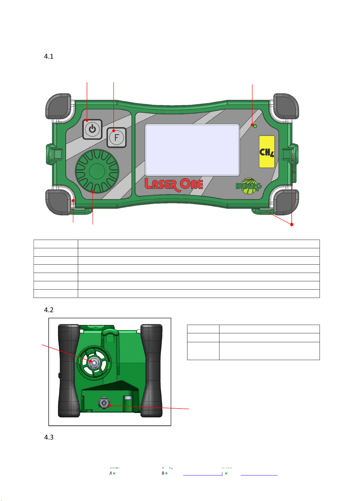
4.1 OVERVIEW OF THE INSTRUMENT..................................................................................................................................................... 7
4.2 CONNECTIONS ........................................................................................................................................................................... 7
4.3 DISPLAY ................................................................................................................................................................................... 7
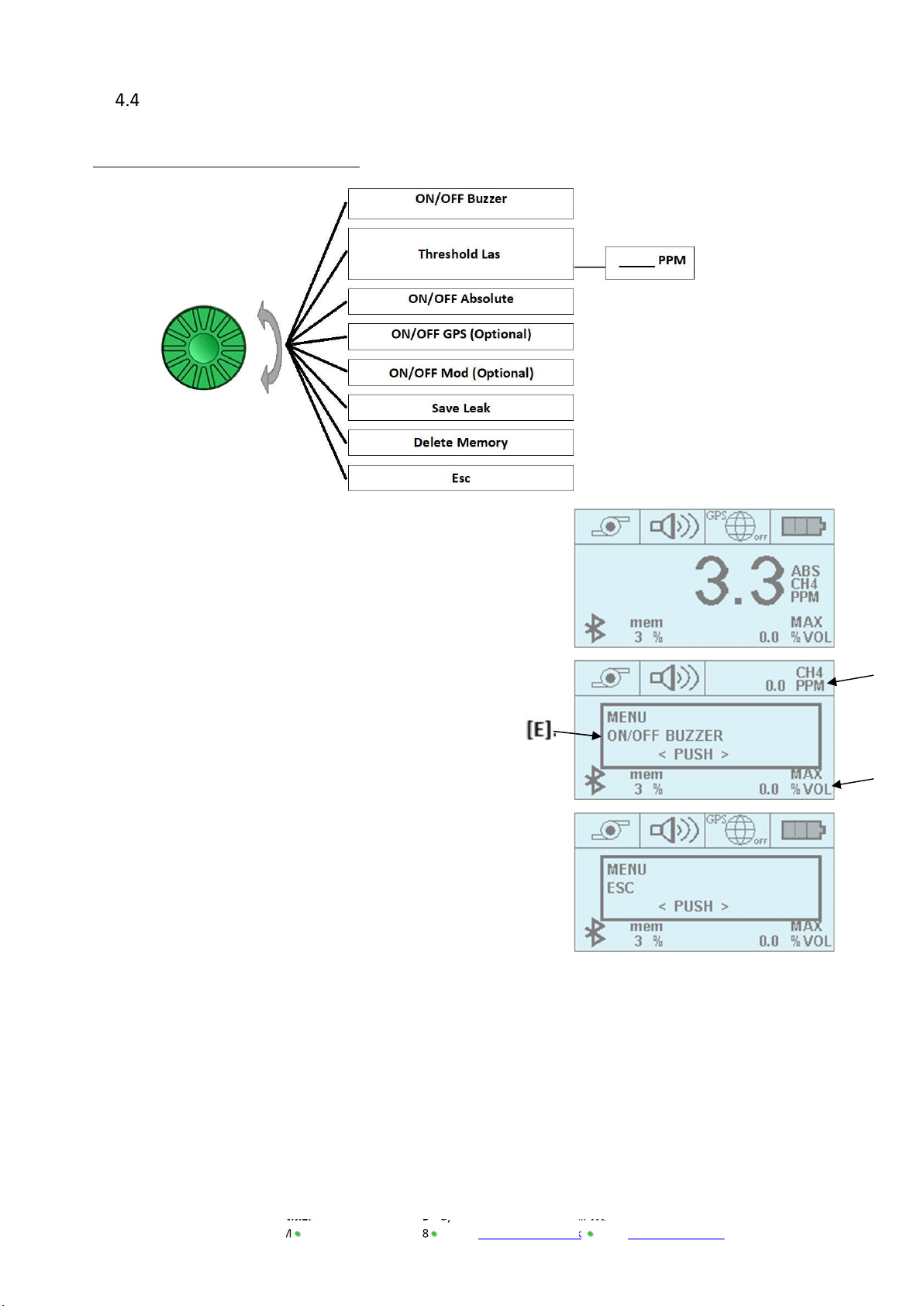
4.4 NAVIGATION SYSTEM (MENU) ....................................................................................................................................................... 9
5 INSTRUMENT’S FUNCTION .................................................................................................................................................. 10
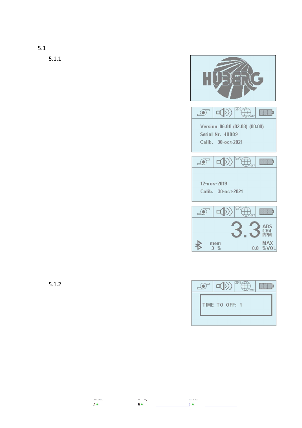
5.1 SWITCHING THE INSTRUMENT ON AND OFF ................................................................................................................................... 10
5.1.1 Switch ON ................................................................................................................................................................... 10
5.1.2 Switch OFF .................................................................................................................................................................. 10
6 START SURVEY..................................................................................................................................................................... 11
6.1 USE OF GPS (OPTIONAL) ........................................................................................................................................................... 11
6.1.1 GPS Activation ............................................................................................................................................................ 11
6.2 SAVING LEAKS .......................................................................................................................................................................... 12
6.3 DELETE DATA ........................................................................................................................................................................... 12
6.4 DESCRIPTION OF THE PNEUMATIC CIRCUITS ..................................................................................................................................... 12
6.4.1 Malfunction of the pneumatic circuit / Pump OFF ..................................................................................................... 12
6.4.2 Restarting the pump operation .................................................................................................................................. 13
6.5 SAVING LEAKS .......................................................................................................................................................................... 13
7 SETTINGS ............................................................................................................................................................................. 14
7.1 MEASUREMENT RANGE ............................................................................................................................................................. 14
7.1.1 Methane measurement ............................................................................................................................................. 14
7.1.2 Measure in absolute mode (ABS) and relative mode (REL) ........................................................................................ 14
7.2 SETTING THE ALARM THRESHOLD .................................................................................................................................................. 15
7.3 ACOUSTIC AND VISUAL ALARM ..................................................................................................................................................... 15
7.4 BACKLIGHT - DISPLAY ILLUMINATION ............................................................................................................................................. 15
7.5 BLUETOOTH DESCRIPTION (OPTIONAL) ....................................................................................................................................... 15
7.6 RECHARGING THE BATTERY PACK ................................................................................................................................................. 16
8 MAINTENANCE .................................................................................................................................................................... 17
8.1 REPLACING THE BATTERY PACK .................................................................................................................................................... 17
8.2 REPLACING THE HYDROPHOBIC FILTER ........................................................................................................................................... 18
9 CH4 ACCURACY TEST ............................................................................................................................................................ 18
9.1 SERVICE AND CALIBRATION ......................................................................................................................................................... 18
9.2 ALARMS AND ERROR INFORMATION .............................................................................................................................................. 19
10 WARRANTY ......................................................................................................................................................................... 20
11 ACCESSORIES ....................................................................................................................................................................... 23
12 APPENDIX A – SAFE USE OF THE INSTRUMENT .................................................................................................................... 24
12.1 LASER RADIATION ..................................................................................................................................................................... 24
12.2 OTHER PRECAUTIONS FOR THE USAGE ............................................................................................................................................ 24
12.3 TESTING AND MAINTENANCE ....................................................................................................................................................... 24
12.4 REPAIR ................................................................................................................................................................................... 24
13 APPENDIX B – TECHNICAL SPECIFICATION ........................................................................................................................... 25
14 APPENDIX C - INFORMATION ON DISPOSAL FOR USERS OF WASTE ELECTRICAL & ELECTRONIC EQUIPMENT ....................... 26
15 APPENDIX D – BLUETOOTH MODULE COMPLIANCE ............................................................................................................. 27
15.1 UNITED STATES ........................................................................................................................................................................ 27
15.2 CANADA ................................................................................................................................................................................. 27
15.3 EUROPE ................................................................................................................................................................................. 28

Page 3 of 30
Q.E.D. ENVIRONMENTAL SYSTEMS LIMITED - Cyan Park - Unit 3, Jimmy Hill Way, Coventry. CV2 4QP.
REGISTERED IN ENGLAND AND WALES NO. 1898734
OMLASERONE Iss. 01
1 DECLARATION OF CONFORMITY
EU Declaratio n of C onf orm i ty
This Declaration of Conformity is issued under the sole responsibility of the manufacturer:
QED Environmental Systems
Cyan Park – Unit 3
Jimmy Hill Way
Coventry
CV2 4QP
UNITED KINGDOM
Product: Laser One and SEM 5000
Type of equipment:
Laser One – Mains Gas and Water Leak Detection
SEM 5000 – Landfill Gas Surface Emissions Monitor
The Laser One and SEM 5000 described above is in conformity with the relevant Union harmonisation
legislation:
2014/34/EU: Equipment and protective systems intended for use in potentially explosive atmospheres
(ATEX)
Ineris (0080) performed assessment against:
EN 60079-0:2012/A11:2013 EN 60079-11:2012 EN 60079-28:2015
Issuing certificate number INERIS 19ATEX0017X.
2014/53/EU: Radio equipment (RED)
EMC (Article 3.2):
EN 301 489-1 EN 301 489-17 EN 301 489-19
EN 61326-1:2012 FCC 15.107/109 + ICES 003
Signed for and on behalf of:
Name: Mr. Craig Millar
Position: Engineering Manager
Done at: QED Environmental Systems

Page 4 of 30
Q.E.D. ENVIRONMENTAL SYSTEMS LIMITED - Cyan Park - Unit 3, Jimmy Hill Way, Coventry. CV2 4QP.
REGISTERED IN ENGLAND AND WALES NO. 1898734
OMLASERONE Iss. 01
2 WARNINGS ATEX
The operating manual must be read and fully understood before using the equipment.
This warning is in place so that the operator fully understands the product and its use within the
application.
Battery must be replaced in a non-hazardous, safe area
Use only with battery pack QED PBLO
Battery pack QED PBLO must only be used with QED LASER ONE or SEM5000
Do not charge the device in a hazardous area OR only charge in a non-hazardous, safe area
Battery charging and communication (USB) must only be done in a non-hazardous, safe area with
adapter QED CCLO 100189
Use only this device to charge QED LASER ONE and SEM5000
Maximum voltage Um ≤ 15V
The maximum voltage that can be applied to the external adapter QED CCLO 100189 to charge
QED LASER ONE and SEM5000 without invalidating the type of protection is 15 volts.
Do not connect the LASER ONE/SEM5000, the battery pack PBLO and adapter CCLO to other
equipment.
These three devices are only designed to be used together to ensure the correct functionality of
the device and guarantee the safety of the operator.
Do not open the device
Only the manufacturer or its authorised representatives can open the device for maintenance and
repair.
Unauthorised opening of the device invalidates the integrity, certification and guarantee of the
product.
ATEX accessories
Use only the following accessories with the instrument LASER ONE:
Rechargeable battery pack lithium ion (PBLO.NNNN.YY 3,7V 4000mAh) Code: 205014
External adapter (CCLO.NNNNN.YY) Code: 100189
Power supply (Um<15 volts) Code: 423007
Car cable power supply Code: 102010

Page 5 of 30
Q.E.D. ENVIRONMENTAL SYSTEMS LIMITED - Cyan Park - Unit 3, Jimmy Hill Way, Coventry. CV2 4QP.
REGISTERED IN ENGLAND AND WALES NO. 1898734
OMLASERONE Iss. 01
Except in a situation of damage or repairs being required, it is recommended that the device is sent to QED
annually for inspection, maintenance, and calibration.
Non-USA USA
Tel: +44(0)333 800 0088 (800) 624-2026
Address: Unit 3 – Cyan Park, Coventry, UK, CV2 4QP 2355 Bishop Circle West, Dexter, MI. 48130, USA
The apparatus type “LASER ONE” “SEM5000”, is usable in gas explosive atmosphere of group IIB and
temperature class T3 for an ambient temperature from -25°C to +50°C.
The apparatus is category 2 and may be used in areas 1 and 2.
The respect of essential safety requirements, defined in annex II of the 2014/34/ UE directive from 26th
February 2014, is obtain by the apparatus conformity to the standards:
EN 60079-0 : 2012 + A11 :2013 Explosive atmospheres – Part 0: Equipment – General
requirements
EN 60079-11:2012 Explosive atmospheres – Part 11. Equipment protection by
intrinsic safety « i »
EN 60079-28:2015 Explosive atmospheres – Part 28. Protection of equipment and
transmission systems using optical radiation.
The following are applied to the apparatus:
Certificate number: INERIS 19 ATEX0017X.
Marking: II 2 G Ex ib op is IIB T3 Gb -25°CTa+50°C
Operating Temperature: -25°C to +50°C
Note: The reduction of the range of temperature (-25°C to +50°C) results from functional conditions only.

Page 6 of 30
Q.E.D. ENVIRONMENTAL SYSTEMS LIMITED - Cyan Park - Unit 3, Jimmy Hill Way, Coventry. CV2 4QP.
REGISTERED IN ENGLAND AND WALES NO. 1898734
OMLASERONE Iss. 01
3 GENERAL DESCRIPTION
The LASER ONE is a digital gas detection instrument manufactured by QED Environmental Systems Ltd.
The intended use of the LASER ONE is to measure low concentrations of Methane in various applications
(leakage survey of natural gas networks, control pinpointing outside buildings, quantifying Methane
levels and laboratory applications for gas analysis).
The LASER ONE instrument has selective measurement of Methane due to the Laser technology used.
The LASER ONE delivers reliable and accurate measurements of Methane concentrations, irrespective
of whether the sample contains other gases or hydrocarbons. Due to its lightweight design and modest
size, LASER ONE can be easily transported and is ideal for measuring Methane concentrations in the field
(landfills, site investigations or gas networks). Its capability to measure from lower concentrations to
higher concentrations changing between ranges rapidly, makes LASER ONE the appropriate instrument
for the detection of leaks from gas meters and the gas distribution network and also as an analyser for
the quantification of gas emissions. Thanks to its metrological sensitivity, accuracy, stability and
response, LASER ONE is particularly suited to any application requiring the measurement of Methane
concentrations in sampling mode or in line (option).
The single-dial function selector makes the LASER ONE easy to use and the large, back-lit LCD display
provides easy to read menus and results. The LASER ONE has a measuring range covering
0 to 1,000,000 PPM (part per million) or 100% Methane concentration.
The LASER ONE also offers a rapid response time, improving the efficiency and saving time. The
exceptional reactivity of the LASER ONE laser technology provides excellent results during field scans for
traces of methane. The noteworthy combination of high sensitivity and rapid response deliver
outstanding measurement quality.
The LASER ONE has the user definable option to switch between ‘Absolute’ and ‘Relative’
measurements, the ‘Absolute’ setting will include the background Methane level or the ‘Relative’ setting
will remove this background level from the subsequent reading (see section 7.1.2).
LASER ONE is equipped with an integral GPS device and the capability to record locational data to
compliment measured gas analysis results. This makes LASER ONE an accomplished instrument to work
conveniently in the field with efficient results.
LASER ONE exists in an ATEX version and has been certified with the intrinsic safety protection mode
and has obtained the following marking:
II 2 G Ex ib op is IIB T3 Gb -25°CTA+50°C
In hazardous environments, the user must adhere to the EN 1127-1:2019 (Explosive atmospheres.
Explosion prevention and protection - Basic concepts and methodology) and the CLC/TR 50404:2003
“Electrostatics Code of practice for the avoidance of hazards due to static electricity”.
Note: The images shown in this user manual are for illustrative purposes only.

Page 7 of 30
Q.E.D. ENVIRONMENTAL SYSTEMS LIMITED - Cyan Park - Unit 3, Jimmy Hill Way, Coventry. CV2 4QP.
REGISTERED IN ENGLAND AND WALES NO. 1898734
OMLASERONE Iss. 01
4 USER INTERFACE
Overview of the instrument
D
escription
[1]
ON/OFF button
+
Backlight
[2]
Function button
[3]
Buzzer
[4]
Jogdial
[L]
LED Alarm Lights and Impact Bumpers
[
S
]
Carry s
trap
Connectors
Connections
Description
[1] Gas Sample Inlet
[2] Battery Charger / Data download
Connector
Display
[1] [2] [3]
[4]
[L] [S]
[1]
[2]
[A] [B] [C] [D]

Page 8 of 30
Q.E.D. ENVIRONMENTAL SYSTEMS LIMITED - Cyan Park - Unit 3, Jimmy Hill Way, Coventry. CV2 4QP.
REGISTERED IN ENGLAND AND WALES NO. 1898734
OMLASERONE Iss. 01
SECTOR DESCRIPTION PRESENT IN ALL VERSION OF LASER
ONE
[A] Pump status YES
[B] Buzzer status YES
[C] GPS status NO
[D] Battery status YES
[E] Measurement of Methane YES
[E1] Type of view: ABS (absolute) – REL (relative) YES
[E2] Unit of Measurement: PPM (parts per million) –
% VOL (volume)
YES
[F] Bluetooth enabled and active NO
[G] % of Memory Used NO
[H] Peak value over last 120 seconds NO
[I] Information (data download, test results etc.) NO
NOTE: When the options C and F are not active, the icons associated with these options are not
displayed.
The icons for G, H and I will only be displayed when the instrument is in logging mode.
[E]
[F] [G]
[
E1
]
[E2]
[H]
[I]

Page 9 of 30
Q.E.D. ENVIRONMENTAL SYSTEMS LIMITED - Cyan Park - Unit 3, Jimmy Hill Way, Coventry. CV2 4QP.
REGISTERED IN ENGLAND AND WALES NO. 1898734
OMLASERONE Iss. 01
Navigation System (menu)
Flow Diagram of the jogdial menu.
Push the jogdial and the menu will appear in the display
window [E].
Rotate the jogdial to scroll through the available menu
options. Once you have identified your desired option, push
the jogdial to confirm your selection.
While a menu is active, the value of the gas is shown in the
upper right corner and in the lower right corner of the display
[D] and [H].
Select “ESC” to exit the Menu.
[D]
[H]

Page 10 of 30
Q.E.D. ENVIRONMENTAL SYSTEMS LIMITED - Cyan Park - Unit 3, Jimmy Hill Way, Coventry. CV2 4QP.
REGISTERED IN ENGLAND AND WALES NO. 1898734
OMLASERONE Iss. 01
5 INSTRUMENT’S FUNCTION
Switching the instrument ON and OFF
Switch ON
Press the ON/OFF button for a few seconds, until the
display is activated.
The start sequence includes several steps:
- Huberg logo.
- Firmware version of the instrument, detector board
information, instrument serial number and next
calibration date.
- Current date / time and next calibration.
If there is data stored in the instrument, you will see the
message "DATA TO DOWNLOAD". In order to download the
data, the ProSoft software must be used.
The instrument will warm up and self-calibrate. The warm
up will last approximately 20-seconds and during this time,
the instrument’s functions are not available for use.
Once the warm up and calibration are complete, the four
LED lights will blink and the alarm will sound.
The LASER ONE is now ready for use.
Switch OFF
To switch off the instrument, press and hold the ON/OFF
button for a few seconds. A shut off message will appear on
the display and a timer will count down. Once the counter
starts to count down the button can be released.

Page 11 of 30
Q.E.D. ENVIRONMENTAL SYSTEMS LIMITED - Cyan Park - Unit 3, Jimmy Hill Way, Coventry. CV2 4QP.
REGISTERED IN ENGLAND AND WALES NO. 1898734
OMLASERONE Iss. 01
6 START SURVEY
Use of GPS (Optional)
After switching the instrument on, the GPS will not be active.
The integral GPS allows the user to save the measured gas level with current GPS coordinates. The
available memory installed in the instrument will give the user the facility to store a full day of
measurements, it can record up to 8 hours. The GPS information is stored every second.
Note: Data is only acquired and saved when the GPS is active.
NB: ---- % means that the instrument is not logging.
GPS Activation
To activate the GPS, press the Jogdial and rotate the dial to
scroll through the menu options until “ON/OFF GPS”
appears. Press the jogdial to confirm the selection. The GPS
icon will change status from “Off” to “Active”.
The percentage of memory used will also be displayed in
the bottom left-hand corner.
Initially, only the percent symbol, (%), will be displayed. Once the GPS has stabilized and the LASER
ONE begins saving data, a number will appear next to the percent symbol to indicate what
percentage of the memory has been used.
Icon Description Icon Description Icon Description
Or
GPS active but
waiting for
signal
Or
GPS off
Or
GPS active
The GPS module is a high-performance receiver with the ability to track up to 20 satellites. The
antenna is a standard, high gain, vehicular type that provides quality tracking performance.
Start-up time for the GPS module can vary according to the strength of the actual signal received.
The presence of high trees or buildings, aerial power lines or other obstructions will affect the signal.
Typically, in an open area, the GPS will obtain a fix in less than a minute.
Note:
In the event of signal loss during the survey, the instrument will continue to log gas values and will
associate the last saved tracked GPS position.

Page 12 of 30
Q.E.D. ENVIRONMENTAL SYSTEMS LIMITED - Cyan Park - Unit 3, Jimmy Hill Way, Coventry. CV2 4QP.
REGISTERED IN ENGLAND AND WALES NO. 1898734
OMLASERONE Iss. 01
Saving leaks
To save a leak into the memory of the instrument, push the jogdial and rotate it until the Menu
“Save Leak” appears. Push the jogdial to save the leak.
This operation is possible only if the GPS is on.
Delete data
To delete the data stored in the instrument, press the jogdial and
rotate it until the menu displays DELETE MEMORY. Press the
jogdial to confirm the selection.
Please Note: There is no secondary confirmation that you want to
delete data.
Description of the pneumatic circuits
The LASER ONE samples using a membrane pump. The typical flow is 0.8 l/m and the minimum flow
is 0.7 l/m.
The use of accessories, such as the probes can slightly reduce this flow. It is advised to only use the
parts and accessories supplied by QED Environmental Systems Limited.
The sample inlet port is suitable for a tube with the dimensions ID2mm X OD4 mm.
An internal hydrophobic filter protects the device against any ingress from dust or water. An
additional external filter is also recommended which can help protect the internal filter.
Warning The Hydrophobic filter is not design to filter anything other than water
or moisture; chemicals may damage the efficiency of the filter.
Please be vigilant when completing a survey and avoid sampling dust
and moisture, as if the filter is too saturated it, may result in serious
damage to the internal sensors.
Malfunction of the pneumatic circuit / Pump OFF
The instrument detects when the pump flow is within normal
operating parameters.
If the flow reduces below certain limits, the pump will stop, the
LEDs will light up, the pump icon will have a ‘X’ overlay and the
message "PUMP ERROR" will be displayed.

Page 13 of 30
Q.E.D. ENVIRONMENTAL SYSTEMS LIMITED - Cyan Park - Unit 3, Jimmy Hill Way, Coventry. CV2 4QP.
REGISTERED IN ENGLAND AND WALES NO. 1898734
OMLASERONE Iss. 01
To toggle the sample pump between its ‘on’ and ‘off’ state, press
the Function button.
When off, the pump icon will have a ‘X’ overlay and the main
display (and ‘%LEL’) will show four horizontal lines.
Warning
The ingress of water or impurities may cause
the
malfunction of the
pneumatic circuit and in some cases the damage to the sensors.
Warning
If the sampling is interrupted or suspended by the pump being turned
off, the instrument will stop logging and horizontal lines (" - - -") will
appear adjacent to the memory capacity percentage.
Restarting the pump operation
To turn the pump ON, press the Function button, the pump will restart and the ‘X’ overlaying the
pump icon will dissapear.
Saving leaks
To end the detection survey, manually stop the GPS or simply turn the instrument off.

Page 14 of 30
Q.E.D. ENVIRONMENTAL SYSTEMS LIMITED - Cyan Park - Unit 3, Jimmy Hill Way, Coventry. CV2 4QP.
REGISTERED IN ENGLAND AND WALES NO. 1898734
OMLASERONE Iss. 01
7 SETTINGS
Measurement Range
Methane measurement
The LASER ONE measurement will be displayed on the main screen
The LASER ONE measurement is selective to Methane only and will not suffer from any cross-gas
contamination from other gases due to the Laser Diode technology used.
The dual range will display the measured Methane from 0-1% in ppmVol (0- 10,000ppm) and above
1% will automatically switch to display the measurement in %Vol up to the full-scale of 100%.
Measure in absolute mode (ABS) and relative mode (REL)
The ‘Absolute’ measurement (ABS), is the measurement of the ambient concentrations which will
include the background level of Methane present in the atmosphere, this is typically between 1.0
and 3.0 ppm.
It may be desirable for the user to remove this background level of Methane during the
measurement survey. The ‘Relative’ measurement (REL) allows for the user to see more easily a
change in the environmental concentration, it may also make a transient leak of gas more visible to
the user as it would act as a contrast between the ambient concentration and the magnitude of the
leak.
When the instrument is in ‘Relative’ (REL) mode, if the detected measurement exceeds a pre-defined
value of 5ppm, the instrument will automatically switch to ‘Absolute’ (ABS) mode. When the
measurement returns to a lower value (i.e. <5ppm), the instrument will automatically switch back to
‘relative’ (REL) mode.
Note: The configuration or settings of the instrument when it is turned off will be remembered
and returned to automatically when next used.
ABS
MODE
REL
MODE

Page 15 of 30
Q.E.D. ENVIRONMENTAL SYSTEMS LIMITED - Cyan Park - Unit 3, Jimmy Hill Way, Coventry. CV2 4QP.
REGISTERED IN ENGLAND AND WALES NO. 1898734
OMLASERONE Iss. 01
Setting the alarm threshold
The alarm threshold can be changed to best suit the application
requirements: the minimum permissible alarm threshold is 1 ppm.
Push the jogdial to display the menu. Rotate the jogdial until the menu
item “Threshold LAS” is visible then push the jogdial to select this
option.
When in the “Alarm threshold” menu, change the ppm threshold by
rotating the jogdial to increase or decrease the value.
To confirm the threshold level, push the jogdial.
Acoustic and visual alarm
When the instrument is powered on, or if a gas measured exceeds the
alarm threshold, an alarm will sound and the LED’s will flash.
To disable or enable this alarm setting, push the jogdial, the option for
‘Buzzer’ is displayed.
Push the jogdial to either disable or enable the Buzzer.
Backlight - Display illumination
To change the display illumination, push the ‘on/off’ button until
you reach the desired illumination.
The display has 4 levels of illumination.
Bluetooth description (OPTIONAL)
If the Bluetooth option has been fitted, the connectivity will always be active and a Bluetooth icon
will be displayed on the main screen.

Page 16 of 30
Q.E.D. ENVIRONMENTAL SYSTEMS LIMITED - Cyan Park - Unit 3, Jimmy Hill Way, Coventry. CV2 4QP.
REGISTERED IN ENGLAND AND WALES NO. 1898734
OMLASERONE Iss. 01
Recharging the Battery Pack
The LASER ONE (SEM5000) is supplied with its rechargeable battery pack (PBLO.NNNN.YY 3,7V 4Ah Code
205014). The charging of the battery is done only using the external adapter CCLO (code 100189) and the
power supply (Code 423007). Connect the charger with the power supply according the figure below, using
the two polarity connectors in conformity with the maximum authorized voltage Um equal to 15V.
The battery charge cycle typically takes 4.5 Hrs, a red led will be on during the charge cycle which
when complete will change to green to indicate a full charge. The battery level indicator on the
LASER ONE consists of three segments, the last of which indicates that there is approximately 30
minutes of power remaining.
The typical operational time from a full charge is 10 hours at an ambient temperature of 20°C and
with the backlight ON.
Advice about the use of lithium ion technology:
In order to optimize the use and the lifetime of your battery, please, follow the following guidelines:
Charge the battery with a temperature between the range [+10°; +30°C]
Allow the battery to reach a complete discharge as frequently as possible
Store in a dry place at a temperature preferably not exceeding 30°C
Central supply connector – Um=15V.
Prosoft Comms For Service Only
Warning: Do not charge the device in a hazardous area OR only charge in a non-hazardous, safe
area.

Page 17 of 30
Q.E.D. ENVIRONMENTAL SYSTEMS LIMITED - Cyan Park - Unit 3, Jimmy Hill Way, Coventry. CV2 4QP.
REGISTERED IN ENGLAND AND WALES NO. 1898734
OMLASERONE Iss. 01
8 MAINTENANCE
Replacing the Battery Pack
Warning Replace the battery pack only in a non-hazardous, safe
area.
Allen Key 3mm
Battery pack
The picture shows the battery pack
outside from its compartment.
1
2
3
4
Unscrew the four
screws

Page 18 of 30
Q.E.D. ENVIRONMENTAL SYSTEMS LIMITED - Cyan Park - Unit 3, Jimmy Hill Way, Coventry. CV2 4QP.
REGISTERED IN ENGLAND AND WALES NO. 1898734
OMLASERONE Iss. 01
Replacing the Hydrophobic Filter
9 CH4 ACCURACY TEST
The instrument can be tested with the test kit comprising of:
- The 10ppm cylinder
- Flow regulator 1l/min.
Service and Calibration
The LASER ONE should be regularly serviced. QED recommends that the instrument is calibrated on
an annual basis.
NOTE: The next calibration date can be seen during the warm up sequence after powering the
instrument and also on a label on the underside adjacent to the battery charging connector.
The hydrophobic internal filter should be checked periodically, (typically this will be weekly during
periods of heavy use).
Unlock the filter by turning it
counterclockwise and remove it.
Change the filter and reassemble
by turning
it clockwise.

Page 19 of 30
Q.E.D. ENVIRONMENTAL SYSTEMS LIMITED - Cyan Park - Unit 3, Jimmy Hill Way, Coventry. CV2 4QP.
REGISTERED IN ENGLAND AND WALES NO. 1898734
OMLASERONE Iss. 01
Alarms and Error Information
The table below gives the different alarm conditions or information about errors.
Displayed Alarm or Error Error Conditions
Acoustic alarm and the LED’s
flash
GAS alarm Concentration measured above the alarm threshold.
The display shows the message
ERROR PUMP, LED’s flash and
the pump icon is crossed
Pump stopped The pump is stopped possibly due to the ingress of
moisture or a high quantity of dust. -
Flashing battery icon
Battery level low The lowest level of the charge capacity has been reached.
There is approximately 30 minutes of use left (at +20°C)
LOW BATTERY message
appears for a short duration
Battery level insufficient The instrument is not able to work and switches off.
The display shows: no com from
laser
Laser fails to
communicate properly
Turn the instrument off and on again. If the error persists,
contact t[email protected].uk
The display shows: Laser sensor
error 130
Laser fails to stabilise
properly
Turn the instrument off and on again. If the error persists,
contact t[email protected].uk
The display shows: Laser sensor
error 135
Laser fails to stabilize
properly
Turn the instrument off and on again. If the error persists,
contact t[email protected].uk
The display shows: Laser sensor
error 150
Laser fails to stabilize
properly
Turn the instrument off and on again. If the error persists,
contact t[email protected].uk
The display shows: Laser sensor
error 142
Laser fails to stabilize
properly
Turn the instrument off and on again. If the error persists,
contact t[email protected].uk
The display shows: Laser sensor
error 144
Laser fails to stabilize
properly
Turn the instrument off and on again. If the error persists,
contact t[email protected].uk
Resetting the alarms:
The table below indicates if it is possible or not to acknowledge and reset the alarm or information
of default when the device is in operation.
Alarm information Possibility of Reset
Threshold of concentration Sound alarm: YES
Flashing red Led: NO
Pump stopped Display indicator: NO
Battery level low Display indicator: NO
This section outlines various warning and error messages which the operator may receive during general
operation of the instrument. For further assistance please contact Technical Support at QED on +44(0)333
800 0088 or email technical@qedenv.co.uk.

Page 20 of 30
Q.E.D. ENVIRONMENTAL SYSTEMS LIMITED - Cyan Park - Unit 3, Jimmy Hill Way, Coventry. CV2 4QP.
REGISTERED IN ENGLAND AND WALES NO. 1898734
OMLASERONE Iss. 01
10 WARRANTY
QED will repair or replace (at QED’s discretion) any goods supplied by the company in respect to defects
arising within 12 months from date of purchase or delivery, whichever is later, provided that:
The model is a LASER ONE gas analyser.
The defect is due to faulty parts or workmanship provided by QED.
Proof of delivery/purchase must be provided to QED for any claims. This includes a QED sales order,
invoice, or delivery note.
All warranty repairs can only be carried out by QED or its authorised agents. In certain circumstances,
permission may be granted by QED for the owner to replace a supplied part under warranty.
Any repair or replacement component under warranty will not extend the warranty period of the
analyser.
Products must have been returned for service and calibration as recommended by QED as per the
individual operating manual.
Where replacement parts have been supplied by QED under warranty, the replaced parts must be
returned to QED. If not returned, QED reserve the right to charge for the replacement part.
If no fault is found an investigation charge may apply.
QED’s Technical Support MUST be notified in the event of a pending warranty claim. They will then issue
a returns reference number that must be included in any return. Failure to provide this will void any
warranty claim.
The following is not included:
Normal wear and tear of parts that might wear out over time, or be consumed, is not covered. Parts not
covered include, but not limited to the PTFE filter and tubing.
A service is not part of a warranty claim.
Accidental damage, including dropping during use.
Damage as a result of vandalism.
Faults arising from use of the equipment that is not in accordance with standard operating procedures
laid out in QED’s operating manual.
Faults arising from use of the equipment in unsuitable applications.
Repairs or alterations carried out by parties other than QED, its authorised agents, or under the
instruction of QED.
Any data stored on the equipment that may be lost.
A claim due to a failure in maintaining the analyser in accordance with the operating manual.
A claim as a result of poor quality or inadequate repairs.
Any business-related losses such as income, profits, and contracts (as far as the law allows).
This manual suits for next models
1
Table of contents
Popular Measuring Instrument manuals by other brands

Middle Atlantic Products
Middle Atlantic Products RackLink owner's manual

YHLO BIOTECH
YHLO BIOTECH VISION ESR Operation manual

Saci
Saci AR4DCT user manual

Carlisle
Carlisle Ransburg IntelliFlow RM2 user manual

Hanna Instruments
Hanna Instruments HI 88703 instruction manual

KMC Controls
KMC Controls SSS-1000 Series installation guide