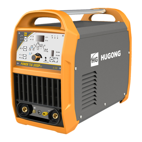
HUGONG INVERMIG 350III User manual

INVERMIG III SERIES
WARNING:
Read carefully and understand all ASSEMBLY AND
OPERATION INSTRUCTIONS before operating.
Failure to follow the safety rules and other basic safety
precautions may result in serious personal injury.
2015VERSION
OWNER’S MANUAL
WELDING AND CUTTING TOTAL SOLUTION

1
CATALOGUE
GENERAL SAFETY RULES
Product Description
Safety Operation
Technical Specifications
Installation and commissioning
Operation
Trouble Shooting
List of Spare Parts
Schematic Circuit Diagram
Complete Set Specifications
Transport & Storage

2
GENERAL SAFETY RULES
WARNING: Read and understand all instructions. Failure to follow all instructions listed
below may result in serious injury.
CAUTION: Do not allow persons to operate or assemble this INVERMIG III SERIES until
they have read this manual and have developed a thorough understanding of how the INVERMIG
III SERIES works.
WARNING: The warnings, cautions, and instructions discussed in this instruction
manual cannot cover all possible conditions or situations that could occur. It must be understood
by the operator that common sense and caution are factors which cannot be built into this product, but
must be supplied by the operator.
SAVE THESE INSTRUCTIONS
IMPORTANT SAFETY CONSIDERATIONS
1.1 Your Welding Environment
-Keep the environment you will be welding in free from flammable materials.
-Always keep a fire extinguisher accessible to your welding environment.
-Always have a qualified person install and operate this equipment.
-Make sure the area is clean, dry and ventilated. Do not operate the welder in humid, wet or poorly
ventilated areas.
-Always have your welder maintained by a qualified technician in accordance with local, state and
national codes.
-Always be aware of your work environment. Be sure to keep other people, especially children, away
from you while welding.
-Keep harmful arc rays shielded from the view of others.
-Mount the welder on a secure bench
or cart that will keep the welder secure and prevent it from tipping over or falling.
1.2 Your Welder’s Condition
-Check ground cable, power cord and welding cable to be sure the insulation is not damaged. Always
replace or repair damaged components before using the welder.
-Check all components to ensure they are clean and in good operating condition before use.

3
1.3 Use of Your Welder
Do not operate the welder if the output cable, electrode, torch, wire or wire feed system is wet. Do not
immerse them in water. These components and the welder must be completely dry before attempting to
use them.
-Follow the instructions in this manual.
-Keep welder in the off position when not in use.
-Connect ground lead as close to the area being welded as possible to ensure agoodground.
-Do not allow any body part to come in contact with the welding wire if you are in contact with the
material being welded, ground or electrode from another welder.
-Do not weld if you are in an awkward position. Always have a secure stance while welding to prevent
accidents. Wear a safety harness if working above ground.
-Do not drape cables over or around your body.
-Wear a full coverage helmet with appropriate shade (see ANSI Z87.1 safety standard) and safety
glasses while welding.
-Wear proper gloves and protective clothing to prevent your skin from being exposed to hot metals, UV
and IR rays.
-Do not overuse or overheat your welder. Allow proper cooling time between duty cycles.
-Keep hands and fingers away from moving parts and stay away from the drive rolls.
-Do not point torch at any body part of yourself or anyone else.
-Always use this welder in the rated duty cycle to prevent excessive heat and failure.
1.4 Specific Areas of Danger, Caution or Warning
Electrical Shock
Electric arc welders can produce a shock that can cause injury or death. Touching
electrically live parts can cause fatal shocks and severe burns. While welding, all metal
components connected to the wire are electrically hot. Poor ground connections are a hazard, so secure
the ground lead before welding.
-Wear dry protective apparel: coat, shirt, gloves and insulated footwear.
-Insulate yourself from the work piece. Avoid contacting the work piece or ground.
- Do not attempt to repair or maintain the welder while the power is on.
-Inspect all cables and cords for any exposed wire and replace immediately if found.
-Use only recommended replacement cables and cords.
-Always attach ground clamp to the work piece or work table as close to the weld area as possible.
-Do not touch the welding wire and the ground or grounded work piece at the same time.
-Do not use a welder to thaw frozen pipes.
Fumes and Gases
-Fumes emitted from the welding process displace clean air and can result in injury or death.
-Do not breathe in fumes emitted by the welding process. Make sure your breathing air is clean and safe.
-Work only in a well-ventilated area or use a ventilation device to remove welding fumes from the
environment where you will be working.
-Do not weld on coated materials (galvanized, cadmium plated or containing zinc, mercury or barium).
They will emit harmful fumes that are dangerous to breathe. If necessary use a ventilator, respirator with
air supply or remove the coating from the material in the weld area.

4
-The fumes emitted from some metals when heated are extremely toxic. Refer to the material safety data
sheet for the manufacturer’s instructions.
-Do not weld near materials that will emit toxic fumes when heated. Vapors from cleaners, sprays and
degreasers can be highly toxic when heated.
UV and IR Arc Rays
The welding arc produces ultraviolet (UV) and infrared (IR) rays that can cause injury to your
eyes and skin. Do not look at the welding arc without proper eye protection.
-Always use a helmet that covers your full face from the neck to top of head and to the back of each ear.
-Use a lens that meets ANSI standards and safety glasses. For welders under 160 Amps output, use a
shade 10 lens; for above 160 Amps, use a shade 12. Refer to the ANSI standard Z87.1 for more
information.
-Cover all bare skin areas exposed to the arc with protective clothing and shoes. Flame-retardant cloth
or leather shirts, coats, pants or coveralls are available for protection.
-Use screens or other barriers to protect other people from the arc rays emitted from your welding.
-Warn people in your welding area when you are going to strike an arc so they can protect themselves.
Fire Hazards
Do not weld on containers or pipes that contain or have had flammable, gaseous or liquid
combustibles in them. Welding creates sparks and heat that can ignite flammable and
explosive materials.
-Do not operate any electric arc welder in areas where flammable or explosive materials are present.
-Remove all flammable materials within 35 feet of the welding arc. If removal is not possible, tightly cover
them with fireproof covers.
-Take precautions to ensure that flying sparks do not cause fires or explosions in hidden areas, cracks or
areas you cannot see.
-Keep a fire extinguisher close in the case of fire.
-Wear garments that are oil-free with no pockets or cuffs that will collect sparks.
-Do not have on your person any items that are combustible, such as lighters or matches.
-Keep work lead connected as close to the weld area as possible to prevent any unknown, unintended
paths of electrical current from causing electrical shock and fire hazards.
-To prevent any unintended arcs, cut wire back to ¼" stick out after welding.
Hot Materials
Welded materials are hot and can cause severe burns if handled improperly.
-Do not touch welded materials with bare hands.
-Do not touch MIG gun nozzle after welding until it has had time to cool down.
Sparks/Flying Debris
Welding creates hot sparks that can cause injury. Chipping slag off welds creates flying debris.
-Wear protective apparel at all times: ANSI-approved safety glasses or shield, welder’s hat and ear plugs
to keep sparks out of ears and hair.

5
Electromagnetic Field
-Electromagnetic fields can interfere with various electrical and electronic devices such as
pacemakers.
-Consult your doctor before using any electric arc welder or cutting device
-Keep people with pacemakers away from your welding area when welding.
-Do not wrap cable around your body while welding.
-Wrap MIG gun and ground cable together whenever possible.
-Keep MIG gun and ground cables on the same side of your body.
Shielding Gas Cylinders Can Explode
High pressure cylinders can explode if damaged, so treat them carefully.
-Never expose cylinders to high heat, sparks, open flames, mechanical shocks or arcs.
-Do not touch cylinder with MIG gun.
-Do not weld on the cylinder
-Always secure cylinder upright to a cart or stationary object.
-Keep cylinders away from welding or electrical circuits.
-Use the proper regulators, gas hose and fittings for the specific application.
-Do not look into the valve when opening it.
-Use protective cylinder cap whenever possible
1.5 Proper Care, Maintenance and Repair
-Always have power disconnected when working on internal components.
- Do not touch or handle PC board without being properly grounded with a wrist strap. Put PC board in
static proof bag to move or ship.
-Do not put hands or fingers near moving parts such as drive rolls of fan
INVERMIG III SERIES USE AND CARE
Do not modify the INVERMIG III SERIES in any way. Unauthorized modification may impair the
function and/or safety and could affect the life of the equipment. There are specific applications for
which the INVERMIG III SERIES was designed.
Always check of damaged or worn out parts before using the INVERMIG III SERIES. Broken
parts will affect the INVERMIG III SERIES operation. Replace or repair damaged or worn parts
immediately.
Store idle INVERMIG III SERIES. When INVERMIG III SERIES is not in use, store it in a secure
place out of the reach of children. Inspect it for good working condition prior to storage and before
re-use.

6
Product Description
INVERMIG III series——INVERMIG III (MMA/MIG/MAG )series IGBT inverter welding-type
semi-automatic welding machine is an inverter DC semi-automatic welding machine, which is widely
used in automation, metal furniture manufacturing, shipyard, pressure container manufacturing and steel
construction industries. This machine employs IGBT module and fast recovery diode as main parts for
power transition and transfer. INVERMIG III can according set value of the welding current Automatic
adjustment the welding voltage and also can according to different wire diameter at the same time
complementary with the corresponding waveform control circuit. it is characterized by little spatter, good
welding surface, higher efficiency, the even adjustment of welding current, welding voltage and dynamic
characteristic, and the protection circuit for overheat, over current, over voltage, less voltage, phase lack,
can ensure the good adaptability and reliability of welding technique. The higher ability of power supply
compensation (not less than 15%) can give the quick response to the change of power supply, work
piece, electrode, and operation.
The feature of INVERMIG III series:
IGBT inverter technology, inverter frequency is up to 20KHz.
Close loop feedback control, stable output voltage, strong ability of power supply compensation
Continuous welding voltage adjustment, accurate match to the different welding current, Unified mode
according to the welding current automatic matching of the corresponding welding voltage
Specially designed dynamic characteristic control circuit, little spatter, good welding surface, higher
efficiency
Arc ending, ball cutting, soft wire feeding
Applicable to CO2 and MAG or MIG welding
Applicable to ф0.8 ~ф1.6 HO8Mn2Si、HO8MnSi、HO4MnSiAITiA、H18CrMnSiA、HO8CrMn2SiMo、
H10MnSiMo、H10MnSiMoTi and so on
Low weight, small volume and high efficiency
Safety Operation
2.1 Operator’s Self- protection
* Please always follow the rules that conform to safety and hygiene. Wear protective garments to avoid
injuries to eyes and skins.
* Use the welding helmet to cover your head while working with the welding machine. Only by viewing
through the filter lens on the welding helmet can you watch your operation.
* Prevent the sparks and spatter from harming your body.
* Under no circumstance can you allow any part of your body to touch the welder’s output bipolarity.
* Do not operate under water or more humid place.
* Fumes and gases produced when welding are hazardous to health. Make sure toworkinplaceswhere
there are exhaust or ventilation facilities to keep fumes or emissions away from the breathing zone.
* Please remember to keep arc rays away from the other nearby people when welding.Thisisonlydue
to the interference from arc rays.

7
2.2 Attention
* The knob on the panel can’t change or adjust with a rush otherwise it will be damaged.
* Check the connection to see if the welder input and output cables are well connected, whether the
earth (ground) connection is reliable, etc.
* Never allow anybody else other than the operator himself to dislocate or modulate the welding
machine.
* Welders have strong electromagnetism and frequency interference, so keep away people with heart
pace or the articles which can be interfered by electromagnetism and frequency.
* No using the way of knocking the torch head to remove slag.
* The torch cable cannot be pressed and its folding angle cannot be too small. The liner radius cannot
less than 150mm, or it may damage the inner cable and lead to accident.
* Never allow anybody else other than the operator himself to access the job site.
* No switching when welding.
* No touching on the electrified parts such as output interface etc. when welding.
* No touching on any other electrified parts while turning on power. Power must be cut off after finishing
job or leaving the site temporarily.
2.3 Safety protection for installation
* Precaution must be taken to keep the operator and the machine from the foreign materials falling from
up above.
* The dust, acid and erodible dirt in the air at the job site can not exceed the amount required by the
mode (excluding the emission from the welder).
* Inflammable or explosive materials are prohibited to access the job site.
* The welder must be installed in the place where it can not be exposed to sun and rain. Also it must be
stored in less humid place with the temperature range at ﹣10 ~40℃.
* There should be 50 ㎝space about for the welding machine to have good ventilation.
* Make sure that there is no metal-like foreign body to enter the welding machine.
* No violent vibration in the welder’s surrounding area.
* Make sure that there is no interference with the surrounding area at the installation site.
2.4 Safety Checking
Each item listed below must be carefully checked before operation:
* Make sure that the welding machine has reliable earth connection.
* Make sure that there is always sound output and input wire connection instead of exposing it outside.
Regular check needs to be conducted by the qualified personnel after the welder has been installed over
a period of six months, which involves as follows:
* Routine cleaning needs to be done to make sure that there is no abmodeal loose parts happening in
the welding machine.
* The parts installed on the panel must guarantee that the welder works properly.
* Check the welding cable to see if it can continue to be used before it is worn out.
* Replace the welder’s input cable as soon as it is found to be broken or damaged.
* Make sure whether there is enough power supply to make the welding machine work properly and the
input power must load the safety protection device.
Notice: Cut off the power supply before opening the case to check.
Please do not hesitate to contact us for technical assistance whenever you come across the problems
you can not work out or you may deem difficult to fix.

8
Technical Specifications
3.1 Working Environment
* The surrounding temperature range: when welding: water cooling: -10 ~﹢40℃,
During transport or in storage:﹣25 ~﹢55℃.
* Relative humidity: when at 40℃: ≤50%, when at 20℃:≤90%.
* The dust, acid and erodible materials in the air can not exceed the amount required by the mode (apart
from the emissions from the welder). No violent vibration at the job site.
* Altitude no more than 1,000m.
* Keep from raining when it is used outdoor.
* The wind speed should no more than 1m/s around the operation places.
3.2 Requirement for Main Supply
* The voltage oscillogram should display actual sine wave,.
* The oscillation of the supplied voltage should not exceed ±15%of the rated value.
3.3 Principle
The machine receive 3~XXXV AC through air switch (SW1), rectify the current by 3 phases
rectifier(BR1), get DC through input reactor (inductance) and capacitance C5 & C9, the current will be
transited to 20KHz AC by IGBT (IGBT 1, IGBT 2), then go to middle frequency transformer (T1) , fast
recovery diode (D1, D12), and output reactor (L0). Finally the machine will have stable DC output for
welding.
3.4 Main construction
INVERMIG III series IGBT welder adopts movable case structure: the upper part of front panel includes
digital current meter, voltage meter, arc ending welding current adjusting knob, arc ending welding
voltage adjusting knob, inductance control adjusting knob, welding function selector press-button,gas
ending arc mode selector press-button, wire diameter adjusting knob, protectd gas selector press-button,
Auto Unified function selector press-button, gas checking press-button,power indicating light, protection
indicating light, working light, The lower part of front panel includes “+” socket, “-” socket, socket of
connecting cable of wire feeder. The back panel includes power cable, ground bolt, and socket of gas
heater, Power swith,Fan.There are four wheels on the bottom of machine, and host ring and handle on
the top of machine.
For the inside of machine, the upper part includes control transformer, 4pcs bcboard.3phase rectifier
bridge,2 IGBT, below have main transformer, the lower part includes secondary fast recovery
diode,radiator and electric reactor,The have power component of radiator is installed in the middle of
machine.
The wire feeder includes motor, speed reducer, wire feeder roll, spool, gas valve, cable connector, gas
hose, welding current potentiometer, welding voltage potentiometer, spot welding switch, etc.
Air torch

9
3.5 Welder Type Coding
* Combination of the Chinese mandarin spelling and the Arabic numerals.
* Implication of Coding:
INVERMIG XXX III
Economic models
Rated welding current(A)
INVERTER CO2/MAG welding machine
3.6 Technical data
3.7 Applied Standard
The INVERMIG III series welder is produced in accordance with the following standard:
3.8 Indicating light
Only Green light on: the machine have input the power.
The red light on: the machine on the welding.
Green light on, yellow light on: The machine is overheated. The machine will go back to working
condition, if the inner temperature of machine returns to the allowed level.
ITEM INVERMIG 350IIII INVERMIG 400IIII INVERMIG 500IIII
Power voltage V 380 400 415 380 400 415 380 400 415
Frequency Hz 50/60
Rate input current A 25.5 29 41.8
Rate input capacity KVA 16.8 20.5 27.5
OCV V 70 73 75 70 73 75 70 73 75
Current range A 40-350 40-400 40-500
Voltage range V 16-31.5 16-34 16-39
Duty cycle % 60
Wire diameter mm 0.8-1.2 0.8-1.6
Efficiency η 85%
Power factor CosΦ 0.92
Insulation class IP21S
Cooling Air
Dimension (L*W*H) mm 953*450*686
Weight kg 51.5 55

10
3.9 Arc ending
Usually there is a crater at the end of welding. It is due to the arc pressure and condensing shrinkage of
melted metal. The higher arc, the more crater. the arc ending function will fill up the crater by arc ending
current (less than 40%-70% of welding current) and improve the welding quality.
3.10 Soft wire feeding
In order to get the satisfying welding quality, the machine feed the wire at preset low speed before wire
touch the work piece. The speed will reach the normal level after striking arc. It means striking arc fail if
the current is not detected during this stage. This kind of striking arc mode can improve the success of
striking arc and ensure the reliable and stable arc.
3.11 Burn back time
When the trigger of torch is switched off, the wire feeding will continue because of inertia. So the wire will
go out to the top end of torch after the welding. It will cause the stick of wire to the work piece, thus bring
the difficulty to the next welding. The burn back is set in the machine to solve this problem. The machine
will keep output voltage during certain time to keep wire burning.
3.12 Waveform control
It means electronic reactor. It can adjust wire burning power by changing the current changing speed,
and reduce the spatter.
3.13 Ball cutting
Usually there is a big droplet at the end of wire after welding. And slag will stick on the low surface of the
droplet. It will cause difficulty of striking arc. The ball cutting circuitisdesignedtocutthedroplet
automatically after welding.
3.14 Post-gas
3 seconds post-gas time is set to protect the welding area after welding.
3.15 Remark & sign
Ground
HGMIG/MAG Welding
AC 3-phase Power Supply, the Rated Frequency is 50Hz.
3-phase Transformer—Rectifier
Direct Current
+ : Current output positive pole
- : Current output negative pole
X: Duty Cycle
I1max...A: Rated Maximum Input Current
I1eff...A: Maximum Virtual Input Current
I2: Rated Welding Current
U0 ...V: Rated No-load Voltage
U1 ...V: Rated Input Voltage
U2: Conventional load voltage
~50/60Hz: AC, Rated Frequency = 50Hz,Can use frequency 60Hz.
...V: Voltage Unit (Volt)
3
~
50
Hz
~
3

11
...A: Current Unit (Ampere)
...KVA: Power Unit (KVA)
...%: Duty Cycle Unit
...A/...V~...A/...V: Output Range. Rated minimum and maximum welding current and related load
voltage.
IP21S: Case Protection Class. ‘IP’ is the code of International Protection. ‘2’ mean preventing user’s
finger from the dangerous parts; preventing the solid material with the diameter no less than 12.5mm
into the box. ‘1’ means preventing water dropping vertically which is harmless. ‘S’ means water proof test
is conducting while the movable parts are standstill.
H: H Insulating Grade.
Installation and commissioning
ATTENTION: The protection class of INVERMIG III series semi-automatic gas shielded welder is IP21S.
It is forbidden to put in a finger or insert a round bar less than 12.5mm (metal bar in particular) into the
welder. No heavy force can be employed on the welder.
Warning! The welder must be grounded before using. No disassembling earth cable if welding is not
end, otherwise, it will do harm to human body. When several welders or with other electrical appliances
are using a common grounding device, they must be parallel connection, series connection is forbidden.
The welder’s ground cable sectional area should not be less than that of input power cable.
4.1. Connection to power supply
* The welder must be loaded in the place where is less dust, no chemical, erodible, inflammable or
explosive gas and goods around the welding site.
* The welder should be installed in the place where it can not be exposed to sun and rain. Also it must be
stored in less humid place with the temperature range ﹣10 ~﹢40℃mm.
* There should be at least 50cm space for the welding machine.
* Apparatus to exclude wind and smoke should be equipped if the inside aeration is not sound.
The power supply for single unit:
INVERMIG 350III INVERMIG 400III INVERMIG 500III
Air switch (A) ≥40 ≥40 ≥60
Fuse (rated working current)
(A)
40 40 60
Knife switch (A) ≥40 ≥40 ≥60
Power cable (mm2) ≥4 ≥4 ≥6
Remark: the fusing current shall be 2 times to rated working current.
4.2 Installation and connection of wire feeder
* Open the spool cover and put the wire on the spool. The wire shall turn counter-clockwise. There is a
damp adjusting device in the wire spool. During rough adjustment, the wire canbepulledbyhand.
Please adjust damp bolt counter-clockwise, if the resistance is too strong, and vice versa.
* Please check the wire feeder roll carefully and make sure the correct roll is used.
* Feed wire to guiding liner of wire feeder, go through roll, the insert wire in brass socket, then press
down the roll to tight.

12
4.3 Connection to wire feeder
* Connect quick connector (male) of connecting cable to the “+” socket on the back panel of welding
machine, and twist the quick connector (male) clockwise to ensure the tight connection. Connect other
end of connecting cable with wire feeder, and ensure the tight connection.
* Connect the joint of 6-core control cable with welding machine and wire feeder respectively.
4.4 Connection gas supply
* Gas regulator in the attached accessories is installed and screwed firmlyonthebottletopreventair
leak.
* Connect and firmly screw the two core plug of heater cable on the gas regulator to “Heater Socket” on
the rear board of welder.
* Connect the one end of gas hose in the attached accessories with the outlet of gas regulator and firmly
hold with hoop also in the attached accessories, the other end to “Gas Inlet” (gas valve joint) on the back
of wire feeder device.
4.5 Connection work piece
Connect quick connector (male) of earth cable to the “-“ socket on the front panel of welding machine,
and twist the quick connector (male) clockwise to ensure the tight connection. The other end clamps
work piece.
4.6 Connection of cables
* For solid wire, connect wire feeder to the “+” output of machine, connect earth cable to “-“output of
machine.
* For flux core wire, connect wire feeder to the “-“output of machine, connect earth cable to “+” output of
machine.
4.7 Commissioning
* Check all connections and make sure all connections and earth are correct before switching on
machine.
Switch on machine, set gas checking switch to “Gas checking”, adjust gas regulator to get required gas
flow, then put gas checking switch to “Welding”.
* Press inching switch on the wire feeder or torch trigger, feed the wire the top end of torch.
* Test welding, adjust the knobs to set welding current adjustment, welding voltage adjustment knob, arc
ending current adjustment, arc ending voltage adjustment knob.
Waning: iron plate and other bad conductor can not be used to connect machinetoworkpiece.

13
Operation
5.1.Front and back panel
1. Socket (+): Connecting Welding cable to wire feeder.
2. Control socket for wire feeder
3. Control Panel GUI: Status display, function selection and welding parameters, when welding the
actual current and voltage display, and so on
4. Cable fixed head ,3phase XXXV/50HZ
5. Heat power socket(AC36V):connecting heater coil of CO2 gas regulator
6. Power fuse(3A) , High voltage, when changed should be cutting the power
7. Air auto switch: When the machine overload or power off suddenly, it is can protect the machine
8. Nameplate
9. Socket ( - ): Connecting earth cable to work-piece.
10. Fan
11.Hoop
5.2Controller of wire feeder
(1) Current adjustment knob:for the current
(2) Manual wire feeder button: for the wire
(3) Voltage adjustment knob:for the voltage

14
5.3 Control Panel GUI
1. Current indication
2. Voltage indication
3. Main power indicator (Green)
4. Protection indicator (Red)
5. Working indicator (red)
6. MIG mode selection button
7. MIG parameter adjustment selection button: is manual. is unified, user can adjust welding
currents and the voltage will matching automatic in unified mode, and the arc length is from -30 to 30,
and 0 is recommend.
8. Gas checking
9. Protective gas option button: CO2 or MIX
10.Wire diameter button:φ1.0/φ1.2/φ1.6 (350-φ0.8/φ1.0/φ1.2)
11. Welding function button: MMA, MIG/MAG
12. Ending arc current adjustment knob: Under MMA is used for adjustment welding current, under
MIG/MAG is used for ending current (wire speed).
13. Ending arc voltage adjustment knob: Under MMA is used for adjustment arcforce,underMIG/MAG
is used for ending voltage.
14. Gas shielded welding electronic reactance adjustment knob
12
3 4 5
6
7
8
9
10
11
12
13
14

15
5.4 Arc ending
Set arc ending mode switch to “ON”.
The operator shall adjust and set welding current, arc ending current, welding voltage, and arc ending
voltage. (Usually the arc ending current is less then welding current, the valve shall be set according to
the crater.). The procedure is: press torch trigger under high OCV condition for inching feeding, striking
arc, release the trigger and the wire will keep burning (the values on the current meter and voltage meter
is welding current and welding voltage), press the trigger again after welding, then the machine is under
arc ending condition (the values on the current meter and voltage meter is arc ending current and arc
ending voltage), release the trigger after the crater is filled up, then arcstop.
Set arc ending mode switch to “OFF”.
The operator shall adjust and set welding current and welding voltage. The procedure is: press torch
trigger under high OCV condition for inching feeding, striking arc, wire will keep burning (the values on
the current meter and voltage meter is welding current and welding voltage), release the trigger after
welding, then arc stop.
5.5 Waveform control
After setting welding current and welding voltage, please adjust electronic reactance adjustment knob
adjusting knob to reduce the spatter, if the spatter is too big.
ATTENTION:
The outer circle of indicating value of welding voltage and arc ending voltage are not value of voltage. It
is adjusting direction.
The “ON’ and ‘OFF” of arc ending can be used under integrative adjustment and independent
adjustment.
The adjusting indication of waveform is not quantitative value, it is adjusting direction.
5.6 Maintenance and service
* As a Hi-Tech machine, the INVERMIG III series welding machine employs many advanced electronic
parts. Proper operation & maintenance conducted by qualified personnel can assure it of good
performance and prolong its operating life. Only the qualified personnel are allowed to be in charge of
repairing. It is strongly recommended customers contact with our company or agent for technical,
repairing, accessories supply and service back-up when they feel unable to work out the technical hitch
or problems.
* Maintenance job should be conducted by the trained personnel. It is never allowable to have hot line
job.
* The newly installed welder or it not in use for some time needs to be surveyed the insulation
resistances between each winding and every winding to case with multimeter, which can not be less
than 2.5MΩ.
* Keep from rain, snow and long term exposing to sunlight when welder is used outdoor.
* If the welder is not in use either for a long time or temporarily, it should be kept dry and have good
ventilation to free it from moisture, eroded or toxic gas. The tolerable temperature ranges from ﹣25 ~
﹢55℃, and the relative humidity can not be more than 90%.
* Dust removal
The professional maintenance personnel should use dry compressed air (use air compressor or bellows)
to remove the dust inside the machine. The part adhering to grease must be cleaned with cloth while
make sure there are no loosing parts existed in the tightened places and connected cable. Usually the
machine should be cleaned once a year if the dust accumulation problem is not very serious, while it

16
needs cleaning once or even twice every quarter if the dust accumulation problem is serious.
* Regularly check the input & output cables of welder to guarantee them right and firmly connected and
avoid them being exposed. Check should be taken once every month when fixed using and every check
taken when removing.
* Regularly check the seal performance of gas system, whether the fan and feeder motor having
abmodeal sound and whether every joint being loose.
* Keep torch cable direct when welding.
* Regularly clean the splash of nozzle (cannot use the way similar to knocking the torch head) and stick
to using splash ointment. Don’t remove the feeder device by means of pulling the torch cable.
* Use qualified wire, no using inferior or rusty wire.
* Clean the dust of liner with compressed air after the welder using some time (the dust is accumulated
by friction between wire and liner) to assure of even wire feeding.
* Please replace the feed roll if find it wear and tear to prevent wire uneven feeding. The pressed roll can
not be pressed too firm to guarantee smooth wire feeding. (It will lead to wire deformation, adding the
feeding resistance and accelerating the friction of gear if pressed over firmly.)
ATTENTION:
* The welder voltage is always higher, so the safety precaution should be taken before repair to
avoid Accidental shock. Under no circumstance can anyone except the professionally trained personnel
open the case of the machine.
* Switch off the power source each time when removing dust.
* No touching inside cable or work piece while removing dust.
Trouble Shooting
* The defects of welding bead
Welding
bead
defects
Reason Solution
Air hole
There is too much oil, rust or water on wire or work-piece Cleanthewireand
work-piece
Poor CO2 gas protection(less gas flow, gas is not pure,
nozzles is blocked, gas leakage, too much wind
Improve the gas
connection
The silicon and manganese in wire is not enough Change to suitable wire
Crack
The current and voltage doesn’t match Adjust the welding data
too much water in the gas change the gas flow
there is too much oil, rust and water on wire or work-piece clean the wire and work
piece
Under cut
arc length is too small, and welding speed is too fast
increase the arc length
and slow the welding
speed
torch location is not good and welding current is too small
adjust the torch
location, and increase
the welding current

17
base plate groove is too deep change the shallow
plate groove
Slag
Inclusion
the former molten slag of welding bead is not cleaned remove molten slag
small current, too much weld slowly deposition, to much
swing during welding
increase the current
and reduce the swing
during welding
Big spatter
welding current and voltage doesn’t match Adjust the welding data
There is too much oil, rust or water on wire or work-piece clean the wire and work
piece
wire is streching too long outside the nozzle press the torch closer to
work-piece
too big diameter of the nozzle Change to suitable
nozzle
Penetration
is not
enough
welding current is too small Increase welding
current
wire is streching too long outside the nozzle press the torch closer to
work-piece
groove is not good,too small angle,too small gap change the welding
technology process
* Common Failure of welding machines and solution
No. Failure Failure reason Solution
F1 Fan is not turing
Fan is broken Change the fan
Loose connection Check where is the loss connection
and tighten it
other Contact the seller
F2 Protection LED is
on
overheat of the internal
machine
Wait till the temperature is coming
down and light is off
Thermal relay is broken Change thermal relay
other Contact the seller
F3
Current and
voltage no display
Current and voltage display is
broken
Change the display
Loose connection Check where is the loss connection
and tighten it
Main control board is broken Change the main control board
Other Contact the seller
F4
When press the
torch button, the
torch is not on
Torch switch is broken Change the torch switch
Cable connection is not
connected Contact the cable
Control board is broken Change or repair the control board
F5 No gas Gas hose is blocked Connect the gas
Gas hose is press Check the gas flow

18
Electropneumatic value is
broken
Repair or change the Electropneumatic
value
Control board is broken Change or repair the control board
F6 Function is ok, but
no wire feeding
Cable connection is not good Connect the cable
Motor is broken Repair or change the motor
Control board is broken Change or repair the control board
F7 current button can
not work
connection is not good or
broken
Connect the cable
Current button is broken Change the button
Other Contact seller
F8 Fan is not turning
or turning slowly
Input power lose phase Check and get the normal input power
Power switch is broken Change the power switch
Fan is broken Change or repair the fan
Connection cable is broken or
lose
Check and repair
F9 No OCV Overheat of internal machine Change F2
Power switch is broken Change the power switch
F10
Machine or cable
is over heating
“+” 、“-”socket is
overheating
Torch power is too small Change the bigger power torch
Cable is too small on diameter Change the suitable cable
Socket is loose Remove the scale cinder and connect
the socket
F11 Power supply is
triping
power is off (more than 2
days)and get power on at first
time
It is not failure, main curicut get power
and triping, shall close the switch
During welding operation Contact seller

19
List of Spare Parts
NO code(EBS)English names specifications unit dosage
111050050447 wire feeder assembly INVERMIG 500E pcs 1
220200010604 feeder fixed axle ¢26.8*210/INVERMIG 500WII pcs 1
311010011794 outside shell INVERMIG 350W pcs 1
420070250045 Power transformer PM500.10.24D33.3.1.1 pcs 1
520070440007 Three phase filter NF313B30/05
440/250VAC/30A pcs 1
611020013994 filter plate WELDMATIC 500I pcs 1
711010050298 Mounting plate INVERMIG 350WII pcs 1
820070430166 Fast recovery tube radiator NB 500E/200*200*100/IGBT pcs 1
911020015851 cylinder baffle TekMaster MIG 250 pcs 1
10 20040300009 Outside force type cable fixed head EG-21(PG21) pcs 1
11 11110270033 Power input wiring harness INVERDELTA 400E pcs 1
12 20070570126 Two core socket DCZ-02 pcs 1
13 20070520004 The insurance holder BF015 pcs 1
14 20030304441 Wire feeding machine communication
interface wiring harness INVERMIG 500E/V1.0 pcs 1
15 11120270006 Transformer wiring harness NB500E pcs 1
This manual suits for next models
3
Table of contents
Other HUGONG Welding System manuals
Popular Welding System manuals by other brands

Parkside
Parkside PISG 120 A2 Operation and safety notes

ims PRO
ims PRO 200E FV CEL manual

Hypertherm
Hypertherm Powermax30 AIR Service manual

EWM
EWM Phoenix 355 Expert 2.0 puls MM TKM operating instructions

Clarke
Clarke weld MIG103NG Operation & maintenance instructions

Lincoln Electric
Lincoln Electric NA-3 Specification sheet

Miller Electric
Miller Electric S-52A owner's manual

Red-D-Arc Welderentals
Red-D-Arc Welderentals DX350 Operator's manual

Miller Electric
Miller Electric Big Blue 302P owner's manual

IO Thrifty
IO Thrifty TC-WELDER user guide

Miller
Miller SQUAREWAVE 1000 owner's manual

Amada
Amada GP-500A-P-DUAL Operation manual