Humminbird AS 12RD2KW User manual

531986-1_A
Humminbir
®
Ra ar
Installation an Operations Manual
Humminbir
®
Ra ar
Installation an Operations Manual
Hummi bird_Radar_Ma ual_531986-1EN_A.qxp:Layout 1 9/19/11 4:37 PM Page 1

N
fo
EN
op
w
R
be
of
800 S
Johns
© 201
i
Thank You
Thank you for choosing Humminbird®, America's #1 name in fishfinders. Humminbird® has built its reputation
by designing and manufacturing top-quality, thoroughly reliable marine equipment. Your Humminbird® is
designed for trouble-free use in even the harshest marine environment. We encourage you to read this
installation and operations manual completely in order to get full benefit from all the features and applications
of your Humminbird® product.
Contact our Customer Resource Center at 1-800-633-1468 or visit our Web site at humminbird.com.
Warnings
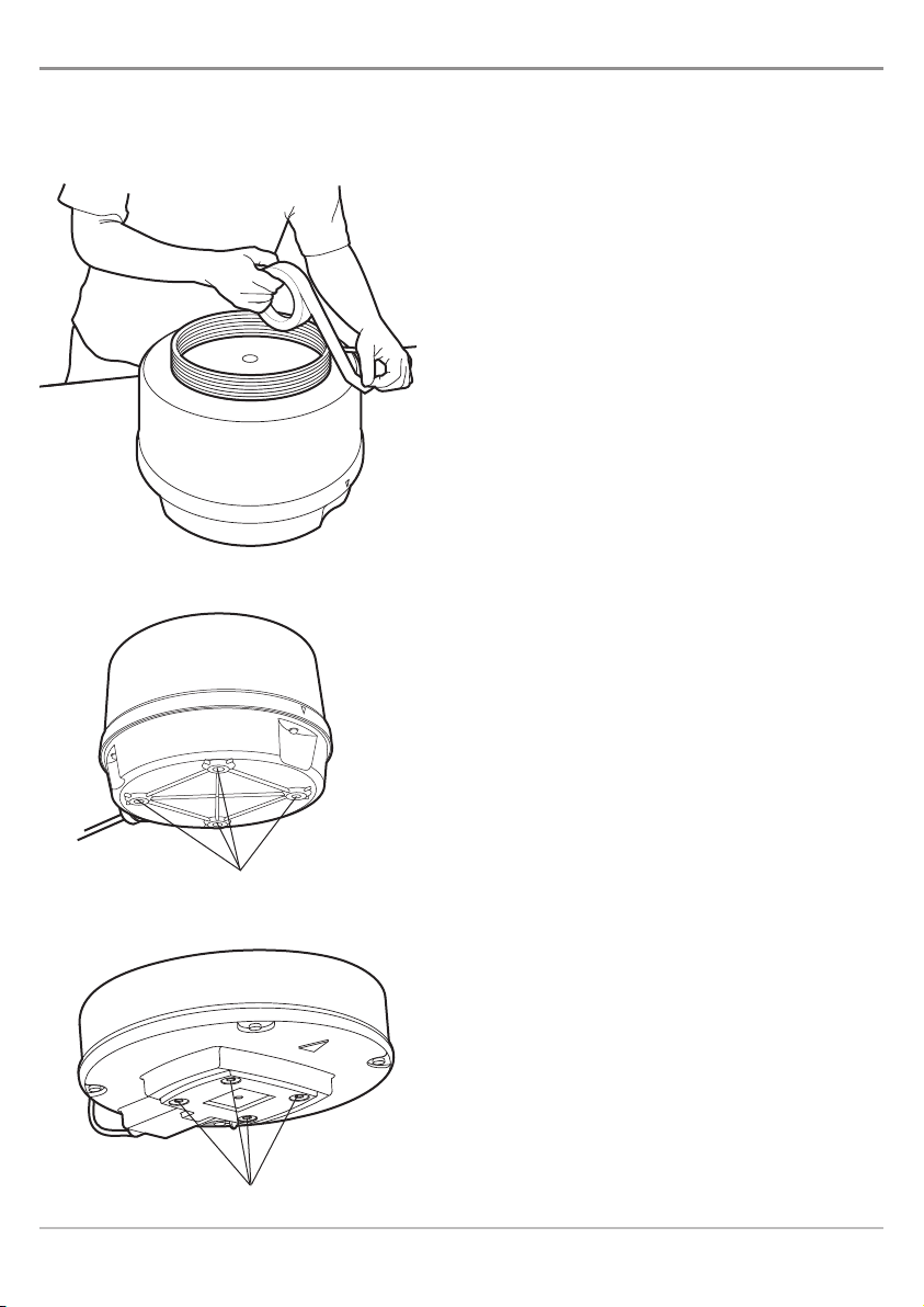
HIGH VOLTAGE WARNING! Dangerously high voltages are present within the scanner unit. There
are no internal connections or adjustments necessary for installation. The cover should be removed
only by a qualified radar service technician. Technicians must exercise extreme care when working
inside the unit. Always remove power before removing the cover. Some capacitors may take several
minutes to discharge, even after switching off the radar. Before touching the magnetron or any high
voltage components, ground them with a clip lead.
CAUTION! nstallation and radar tuning should only be performed by a qualified radar service
technician.
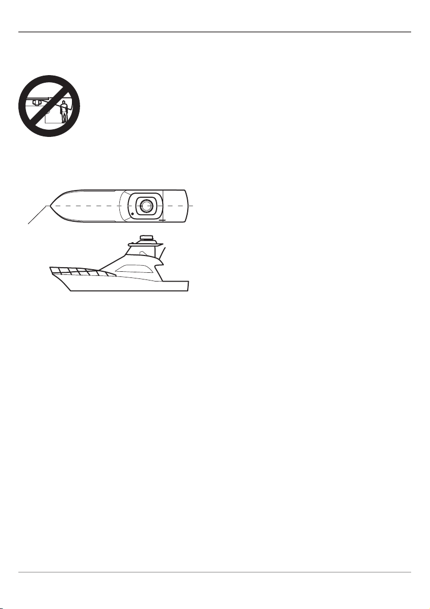
DANGER: MICROWAVE RADIATION HAZARD! The microwave energy radiated by a radar antenna
is harmful to humans, especially to one’s eyes. Never look directly into an open waveguide or into
the path of radiation from an enclosed antenna. Radar and other radio frequency radiation can upset
cardiac pacemakers. f someone with a cardiac pacemaker suspects abnormal operation,
immediately turn off the equipment and move the person away from the antenna. Turn off the radar
whenever it is necessary to work on the antenna unit or on other equipment in the beam of the radar.
WARNING! How to interpret the radar display is not included in this manual. The captain is responsible
for the proper use of radar and the safety of the vessel and its passengers.
WARNING! This device should not be used as a navigational aid to prevent collision, grounding, boat
damage, or personal injury. When the boat is moving, water depth may change too quickly to allow
time for you to react. Always operate the boat at very slow speeds if you suspect shallow water or
submerged objects.
WARNING! The electronic chart in your Humminbird® unit is an aid to navigation designed to
facilitate the use of authorized government charts, not to replace them. Only official government
charts and notices to mariners contain all of the current information needed for the safety of
navigation, and the captain is responsible for their prudent use.
WARNING! Disassembly and repair of this electronic unit should only be performed by authorized
service personnel. Any modification of the serial number or attempt to repair the original equipment
or accessories by unauthorized individuals will void the warranty.
WARNING! This product contains chemicals known to the State of California to cause cancer and/or
reproductive harm.
Hummi bird_Radar_Ma ual_531986-1EN_A.qxp:Layout 1 9/19/11 4:37 PM Page i

NOTE: This product is specifically designed to be installed on boats and other means of maritime transport. If your country
forms part of the EU, please contact your dealer for advice before attempting to install elsewhere.
ENVIRONMENTAL COMPLIANCE STATEMENT: It is the intention of Humminbird® to be a responsible corporate citizen,
operating in compliance with known and applicable environmental regulations, and a good neighbor in the communities
where we make or sell our products.
ROHS STATEMENT: Product designed and intended as a fixed installation or part of a system in a vessel may be considered
beyond the scope of Directive 2002/95/EC of the European Parliament and of the Council of 27 January 2003 on the restriction
of the use of certain hazardous substances in electrical and electronic equipment.
800 Series™, 900 Series™, 1100 Series™, Humminbird®, and -Press™ Menu are trademarked by or registered trademarks of
Johnson Outdoors Marine Electronics, Inc.
© 2011 Johnson Outdoors Marine Electronics, Inc., Eufaula AL, USA. All rights reserved.
NOTE: Some features discussed in this manual require a separate purchase, and some features are only available on
certain models. Every effort has been made to clearly identify those features. The illustrations in this manual may look
different than your display, but your model will operate in a similar way. Please read the manual carefully in order to
understand the full capabilities of your model.
ii
ation
rd® is
d this
ations
e
d
g
al
h
e
a
o
et
n,
ar
r.
e
at
w
or
o
nt
of
d
nt
or
Hummi bird_Radar_Ma ual_531986-1EN_A.qxp:Layout 1 9/19/11 4:37 PM Page ii

Rada
Ad
Ch
Dis
Adjus
Ad
Ad
Ad
Ad
EBL/V
Cre
Cre
Ed
De
Spec
Cont
Tab
iii
Thank You i
Warnings i
ow Radar Works 1
Prepare for Installation 2
Choose the Mounting Location 4
AdjustforObstacles........................................................................ 6
ShiftingfromtheCenterLine................................................................. 6
ObtainingSufficientDipAngle................................................................ 7
MountingBase............................................................................ 7
Installation 8
AS12RD2KW:Scanner nstallation............................................................ 8
AS21RD4KW:Scanner nstallation........................................................... 10
ConnectPower ........................................................................... 12
Start/Stop Radar Transmission 15
StartTransmissionorStartTimedTransmission..................................................15
SetTimedTransmissionSettings..............................................................15
StopTransmission .........................................................................15
Radar Configuration (installation and repair only) 16
OpentheRadar nstallationMenu............................................................16
TunetheRadar............................................................................17
AdjusttheTriggerDelay ....................................................................17
SettheMainBangSuppression..............................................................18
SettheSectorBlankingRange...............................................................18
AdjusttheHeadingLine ....................................................................19
Radar Operations 20
Menus...................................................................................20
Views 22
RadarView...............................................................................22
Chart/RadarComboView(GPSRequired) ......................................................23
Table of Contents
Hummi bird_Radar_Ma ual_531986-1EN_A.qxp:Layout 1 9/19/11 4:37 PM Page iii

iv
Radar Display Settings 24
Adjust nterferenceRejection ................................................................24
ChangetheRadarDisplayPalette.............................................................24
DisplayRangeRings .......................................................................24
Adjust Radar Settings 25
AdjustSTCSettings........................................................................25
AdjustGainSettings .......................................................................25
AdjustFTCSettings........................................................................25
AdjusttheTransmissionRange...............................................................25
EBL/VRM 26
CreateanEBL/VRMwiththeCursor(GPSRequired)..............................................26
Create an EBL/VRM with the X-Press™Menu...................................................27
EditanEBL/VRMPair.......................................................................28
DeleteanEBL/VRM........................................................................28
Specifications 29
Contact umminbird® 31
Table of Contents
i
i
1
2
4
. . . 6
. . . 6
. . . 7
. . . 7
8
. . . 8
. . 10
. . 12
15
. . 15
. . 15
. . 15
16
. . 16
. . 17
. . 17
. . 18
. . 18
. . 19
20
. . 20
22
. . 22
. . 23
Hummi bird_Radar_Ma ual_531986-1EN_A.qxp:Layout 1 9/19/11 4:37 PM Page iv

How
The w
micro
in its
beari
mark
By kn
anten
repea
depe
Hummi bird_Radar_Ma ual_531986-1EN_A.qxp:Layout 1 9/19/11 4:37 PM Page v

How Radar Works
1
How Ra ar Works
The word “radar” is an acronym for “Radio Detecting And Ranging.” A radio transmitter sends a quick
microwave pulse, and then a receiver listens for that signal’s echo when it is bounced back from something
in its path. The returning signal is processed by a computer to determine its relative distance, position, and
bearing. This information is graphically displayed on a view for you to see. Other boats or ships, navigational
markers, and landmasses are referred to as targets.
By knowing how long it takes for a signal to return, the distance to a target can be determined. As the radar
antenna scans through a 360-degree rotation, it can show where the target is relative to your position. By
repeated scans, you can see which direction another boat is moving. How a target is displayed on the screen
depends on the target’s height and size as well as its material and shape.
How radar will perform is mostly determined by the antenna
or scanner. ncreasing the size of the antenna improves
long-range performance and target discrimination, or the
ability to distinguish two separate targets at a distance. The
critical factors are the antenna’s beam width and side lobe
level. Typically, a radar antenna will radiate a tightly focused
beam from the front of the array. The longer the antenna
array is, the narrower the beam width will be. Additionally,
it will also emit smaller amounts of energy to each side. The
lower the side lobe level, the less the effect of a false echo.
WARNING! How to interpret the radar display is not included in
this manual. The captain is responsible for the proper use of radar
and the safety of the vessel and its passengers.
SideLobeLevel
Boat and Surrounding Targets Radar Display
Hummi bird_Radar_Ma ual_531986-1EN_A.qxp:Layout 1 9/19/11 4:37 PM Page 1

AS 1
N
in
AS 2
N
in
*B
B
Prepare for Installation
Before you begin installation, it is important to review the installation instructions and check the hardware
to confirm that you have all of the required equipment.
Supplies: n addition to the hardware included in this
box, you will also need vinyl tape, a powered hand drill
and various drill bits, various hand tools, safety glasses,
a dust mask, and sealant.
1. Unpack the box and confirm the contents
with the illustration shown on the next
page.
2. Coil the cable and place the cable on top of
the scanner. Secure the cable with tape.
3. nvert the scanner and make sure the four
mounting holes are clear to accept bolts.
Securing the Cable with Tape
Clearing the Mounting oles (AS 12RD2KW)
4 Mounting Holes
Clearing the Mounting oles (AS 21RD4KW)
4 Mounting Holes
2
Installation
Hummi bird_Radar_Ma ual_531986-1EN_A.qxp:Layout 1 9/19/11 4:37 PM Page 2

AS 12RD2KW: Box Cont nts*
Scanner/Antenna (1)
Lock Washers (4)
Bolts, Hex Metric M8 x 25mm (1 in.) (4)
Flat Washers (4)
5A Fuses (2)
Adapter Cable (1)
NOTE: Do not remove the cover from the unit. There are no connections or adjustments inside the unit that are needed for
installation or operation. The cable must remain attached.
AS 21RD4KW: Box Cont nts*
Scanner/Antenna (1)
Lock Washers (4)
Bolts, Hex Metric M10 x 25mm (1 in.) (4)
Flat Washers (4)
8A Fuses (2)
Adapter Cable (1)
NOTE: Do not remove the cover from the unit. There are no connections or adjustments inside the unit that are needed for
installation or operation. The cable must remain attached.
*Box contents and features are subject to change without notice.
F
E
A
B
C
D
E
F
D
C
B
A
A
BCD
E
F
F
E
D
C
B
A
3
ware
n this
d drill
sses,
of
r
Installation
Hummi bird_Radar_Ma ual_531986-1EN_A.qxp:Layout 1 9/19/11 4:37 PM Page 3

Choose the Mounting Location
t is important to consider the following information when installing the scanner on the boat. Also, see Adjust
for Obstacles for more information.
WARNING!
Do NOT install the radar in a location that exposes passengers and crew to the radar beam. Do NOT mount
the radar where it could radiate on any person.
CAUTION! Working at higher elevations may become necessary while installing the scanner unit. Observe safety measures
and take sufficient precautions to avoid personal injury or damage to the equipment.
Center Line: The scanner unit should be mounted on
the center line of your boat in a location that has an
unobstructed view forward and is as clear as possible
the rest of the way around the unit.
eight: Choose a location as high as practical to
improve maximum range; however, keep in mind that
minimum range objects may be overlooked if mounted
too high.
Unobstructed View: Position the unit forward of large
structures and exhaust stacks. Large structures or
stacks cause blind spots. Contamination from engine
exhaust on the scanner housing reduces radar
performance.
• Antennas for GPS, radio communication, or other
equipment should not be located in the radar
beam.
• Use non-metallic extension poles to move the
active area of antennas above the radar beam.
Continued on next page...
Center line
of boat
4
Installation
Hummi bird_Radar_Ma ual_531986-1EN_A.qxp:Layout 1 9/19/11 4:37 PM Page 4

Surface: The mounting surface must be flat and approximately parallel with the boat’s water line.
Surface Thickness: The mounting surface must support the weight of the scanner. The
recommended surface thickness is 3/8 to 1/2 in (9.5 mm to 13 mm). f the mounting surface is thin,
a doubler should be added. f it is thicker than recommended, longer bolts must be purchased
separately.
CAUTION! The scanner will be damaged if the bolts protrude more than 1/2 inch (13 mm).
Access: Access to the under side is required for installation of the mounting bolts.
Cable Routing: Test the cable route from the scanner to the control head and power location. Avoid
routing the interconnecting cable through areas of possible damage, from moving objects, machinery,
exposure to chemicals, or high temperature. See Installation: Connect Power for more information.
3/8”-1/2”
Mounting Surface (AS 21RD4KW)
Flat Surface &
parallel to water line
Underside Access
Minimum
Surface
Thickness
(9.5 - 13 mm)
3/8”-1/2”
Mounting Surface (AS 12RD2KW)
Flat Surface &
parallel to water line
Underside Access
Minimum
Surface
Thickness
(9.5 - 13 mm)
5Installation
djust
nt
es
ed on
as an
ssible
al to
that
unted
large
es or
ngine
radar
her
dar
he
m.
Hummi bird_Radar_Ma ual_531986-1EN_A.qxp:Layout 1 9/19/11 4:37 PM Page 5

Installation 6
A just for Obstacles
Obstacles in the radar beam (such as a ship mast) can cause shadow zones, which will prevent you from
seeing targets behind the obstacle. Use the following sections to ensure a clear view for the radar.
Shifting from th C nt r Lin
Shift the scanner position from the center line to the starboard side of the boat to move shadow zones to
the port side. This makes it possible to keep a clear view to the bow. The distance to be shifted can be
calculated using the following equation:
Ls=0.4R+D/2 [m] (when R<15m)
Ls=0.025R+D/2 [m] (when R>=15m)
where: Ls = distance to be shifted from center line
D = diameter of obstacle on center line
R = distance from scanner to obstacle
R
D
Ls
Scanner Unit
Shifting from the Center Line (AS 21RD4KW)
Center ine
Obstacle
R
D
Ls
Scanner Unit
Shifting from the Center Line (AS 12RD2KW)
Center ine
Obstacle
Obta
Raise
scann
long-
the s
Mou
The s
certa
N
st
Hummi bird_Radar_Ma ual_531986-1EN_A.qxp:Layout 1 9/19/11 4:37 PM Page 6

Installation
from
es to
an be
7
Obtaining Suffici nt Dip Angl
Raise the scanner position so that there is a sufficient dip angle available between the line of sight from the
scanner to the obstacle and the horizontal line. By raising the dip angle 5°, it is possible to prevent mid- and
long-distance shadow zones. Don’t adjust the dip angle too high since the radar cannot detect objects below
the sight line.
Mounting Bas
The scanner can be installed directly to a roof or other flat surface. You can also use a mounting bracket. Be
certain you keep the water drain tube clear. t is located at the bottom of the scanner unit.
NOTE: If the mounting bracket or surface has a curvature of more than 2 mm, use spacers with the mounting bolts to prevent
stress on the scanner housing.
Do not mount on a
surface with an
edge that might trap
water.
Mounting
surface is
clear and doesn’t
trap water
Incorrect Mounting BaseCorrect Mounting Base
Horizontal ine
Dip Angle
Sight ine
Hummi bird_Radar_Ma ual_531986-1EN_A.qxp:Layout 1 9/19/11 4:37 PM Page 7

Installation
After you have chosen the mounting location, proceed to the installation section that matches your scanner
model.
AS 12RD2KW: Scann r Installation
1. Confirm that the mounting location meets the requirements described in the section Choose the
Mountin Location.
2. Clean and dry the mounting surface.
3. Align the included template squarely with the center line of the boat (or chosen mounting
location), with the arrow pointing forward. Mark the four mounting holes.
NOTE: Check the template to confirm that the dimensions match the unit. Reproduction and moisture
can affect the size of the template.
4. Drill four 3/8 in. (10 mm) diameter holes through the mounting surface.
5. Check that each bolt (with lock washer and flat washer) protrudes through the mounting surface
at least 5/16 in. (8 mm) but less than 1/2 in. (13 mm).
CAUTION! The scanner will be damaged if bolts protrude more than 1/2 in. (13 mm).
6. Apply sealant around each mounting hole.
7. Place the scanner unit on the mounting surface. Orient the scanner with the index mark on the
housing facing forward (cable notch facing aft).
8. nstall and tighten the four bolts as shown in the illustration Mountin the Scanner Unit.
9. Uncoil the scanner cable.
10. Secure the cable near the scanner to support the weight of the cable and prevent strain on the
watertight cable seal. f the cable is to pass through tubing or a bulkhead, protect the unfinished
end. Do not use the unfinished wires or fabric braid to pull the cable.
11. Route the cable to the operator’s location, securing it at appropriate points along the way. Make
a drip loop and apply sealant at the entry point of an exterior bulkhead. Proceed to Connect
Power.
8
Installation
Hummi bird_Radar_Ma ual_531986-1EN_A.qxp:Layout 1 9/19/11 4:37 PM Page 8

Mounting the Scanner Unit (AS 12RD2KW)
CAUTION! The scanner will be damaged if the bolts
protrude more than 1/2 in. (13 mm).
Index Mark
(faces forward)
Mounting Surface
(partial view)
Flat Washer
ock Washer
Bolt
Scanner Orientation (AS 12RD2KW)
Index Mark Facing Forward
Cable Notch Facing Aft
9Installation
anner
he
ng
ace
he
he
ed
ake
ect
Hummi bird_Radar_Ma ual_531986-1EN_A.qxp:Layout 1 9/19/11 4:37 PM Page 9

AS 21RD4KW: Scann r Installation
1. Confirm that the mounting location meets the requirements described in the section Choose the
Mountin Location.
2. Clean and dry the mounting surface.
3. Align the included template squarely with the center line of the boat (or chosen mounting
location), with the arrow pointing forward. Mark the four mounting holes.
NOTE: Check the template to confirm that the dimensions match the unit. Reproduction and moisture can
affect the size of the template.
4. Drill four 1/2 in. (13 mm) diameter holes through the mounting surface.
5. Check that each bolt (with lock washer and flat washer) protrudes through the mounting surface
at least 5/16 in. (8 mm) but less than 1/2 in. (13 mm).
CAUTION! The scanner will be damaged if bolts protrude more than 1/2 in. (13 mm).
6. Apply sealant around each mounting hole.
7. Place the scanner unit on the mounting surface. Orient the scanner with the index mark on the
housing facing forward (cable notch facing aft).
8. nstall and tighten the four bolts as shown in the illustration Mountin the Scanner Unit.
9. Uncoil the scanner cable.
10. Secure the cable near the scanner to support the weight of the cable and prevent strain on the
watertight cable seal. f the cable is to pass through tubing or a bulkhead, protect the unfinished
end. Do not use the unfinished wires or fabric braid to pull the cable.
11. Route the cable to the operator’s location, securing it at appropriate points along the way. Make
a drip loop and apply sealant at the entry point of an exterior bulkhead. Proceed to Connect
Power.
10
Installation
Hummi bird_Radar_Ma ual_531986-1EN_A.qxp:Layout 1 9/19/11 4:37 PM Page 10

Mounting the Scanner Unit (AS 21RD4KW)
Mounting Surface
(partial view)
Flat Washer
ock Washer
Bolt
CAUTION! The scanner will be damaged if the
bolts protrude more than 1/2 in. (13 mm).
Scanner Orientation (AS 21RD4KW)
Index Mark Facing Forward
Cable Notch Facing Aft
11 Installation
he
ng
ace
he
he
ed
ake
ect
Hummi bird_Radar_Ma ual_531986-1EN_A.qxp:Layout 1 9/19/11 4:37 PM Page 11

Connect Power
Use the following instructions to connect power to the scanner unit. Also, see the illustration and table for
more information.
1. Route the cable to the fuse panel or battery (12V to 20 VDC required). Make sure that the Data
connector can also reach the control head.
2. Connect the Large Black wire to the negative (-) terminal of the fuse panel or battery.
3. Connect the Large White wire (with the in-line fuse) to the positive (+) terminal of the fuse panel
or battery.
NOTE: Do not remove the in-line fuse unless a dedicated and fused terminal is available. If so, install a 5A
fuse (AS 12RD2KW) or an 8 Amp fuse (AS 21RD4KW).
4. The green and blue wires must connect to enable radar (open = disabled, closed = enabled).
The installation options are as follows:
To connect the scanner to an On/Off switch or relay: Connect the small green wire to the
normally closed lead and the small blue wire to the normally open lead.
If you are not connecting the scanner to an On/Off switch or relay, connect the wires
together.
NOTE: The On/Off Switch or relay is optional. Please contact our Customer Resource Center for more
information.
NOTE: The On/Off control switch or relay provides a signal that controls the DC power inside the scanner
unit. It does not switch the main power leads to the scanner unit.
5. Plug the Data Connector into the adapter cable.
6. Connect the adapter cable to the control head's Ethernet port. Hand-tighten the screw nut.
7. Proceed to Radar Configuration.
12
Installation
Hummi bird_Radar_Ma ual_531986-1EN_A.qxp:Layout 1 9/19/11 4:37 PM Page 12

*The On/Off Switch or relay is optional. Please contact our Customer Resource Center for more information. The green and
blue wires must connect to enable radar (open = disabled, closed = enabled).
Function Wire Color Notes
1
Battery (+) Large White DC 12V to DC 20V
2
Battery (-) Large Black 0 Volts (ground)
3
*Switch, relay, Small Green Normally Closed Lead
4
or terminated Small Blue Normally Open Lead
5
Data -
}Enable/Disable
Connects to the adapter cable, which connects to the
control head Ethernet Port.
Power Connection (AS 21RD4KW)
1
2
3
4
5
Power Connection (AS 12RD2KW)
1
2
3
4
5
13 Installation
le for
ata
nel
d).
he
res
Hummi bird_Radar_Ma ual_531986-1EN_A.qxp:Layout 1 9/19/11 4:37 PM Page 13

Installation 14
800/900 Series™(rear view)
Ethernet Port
1100 Series™(rear view)
Ethernet Port
Sta
Use t
Start
Set T
Use T
Stop
N
Hummi bird_Radar_Ma ual_531986-1EN_A.qxp:Layout 1 9/19/11 4:37 PM Page 14
Table of contents
Other Humminbird Radar manuals
Popular Radar manuals by other brands

Preco
Preco PreView Side Defender SDR8503 operating manual

Ametek Drexelbrook
Ametek Drexelbrook Impulse T Series Installation and operating instructions

Furuno
Furuno WR2120 Operator's manual

Carmanah
Carmanah G Series Cabinet Door Replacement Guide

Radarsign
Radarsign TC-400 Operation manual

TRANSIENT
TRANSIENT VIY5-125 user manual

Preco
Preco PreView WorkSight for Waste w/VL ZC Quick installation guide

RHYTHM
RHYTHM Hawkeye troubleshooting guide

FLIR
FLIR Ranger R Series Operator's manual

SPX
SPX Radiodetection SENSORS & SOFTWARE LMX150 Operation manual

Endress+Hauser
Endress+Hauser Micropilot S FMR540 manual

Endress+Hauser
Endress+Hauser Micropilot FMR56 Brief operating instructions