Humminbird 531871-1_A User manual

Un t Sw tch
1
531871-1_A
Thank You
Thank you for choosing Humminbird®, America's #1 name in fishfinders. Humminbird® has built its reputation by
designing and manufacturing top-quality, thoroughly reliable marine equipment. Genuine Humminbird® accessories
offer the opportunity to upgrade and expand the capabilities of your Humminbird® product.
Your Humminbird® is designed for trouble-free use in even the harshest marine environment. In the unlikely event that
your Humminbird® does require repairs, we offer an exclusive Service Policy - free of charge during the first year after
purchase, and available at a reasonable rate after the one-year period. For complete details, see the Warranty section
included in this manual.
Contact our Customer esource Center at 1-800-633-1468 or visit our Web site at humm nb rd.com.
Installation Overview
Following are instructions for the installation of this accessory. Before you start installation, we encourage you to read
these instructions carefully in order to get the full benefit from your Humminbird® accessory. If you find that any items
are missing from your installation kit, call our Customer esource Center at 1-800-633-1468 or visit our Web site at
humm nb rd.com.
The Unit Switch comes with all the necessary hardware to allow you to connect your two control heads to one
transducer. The switch is intended for installation on the console, and will work well on almost any boat.
NOTE: The Unit Switch will not allow the six beam-3D transducer to be shared.
Suppl es: In addition to the hardware supplied with your Unit Switch, you will need a hand drill with various size bits,
a Phillips screwdriver, an adjustable wrench, and a 3 amp fuse.
700 SERIES™ NOTE: If you are installin the Speed Sensor accessory (optional), you will also need to purchase the
Sonar/Speed Y-Cable. Contact our Customer Resource Center for details at 1-800-633-1468 or visit our Web site at
humm nb rd.com.
Installation
Before installing the Unit Switch, gather all the parts you will need, and make sure that the planned location of the
Unit Switch will allow you to connect the two control heads to your transducer. Perform the procedures in the
following sections to install the Unit Switch on your boat.
1. Locat ng the Un t Sw tch Mount ng Pos t on
There are two ways to find the mounting location, as follows:
Sw tch Panel: If your console already contains a switch panel with an available slot, slide the Unit Switch into the
slot until it snaps into place. Then skip ahead to procedure two.
In-Dash: If your console does not have a switch panel or a pre-made mounting location, you will need to create
one yourself.
Mount ng the Sw tch
Boat Console
Switch
© 2011 Humminbird®, Eufaula AL, USA.
All rights reserved.
Un t Sw tch

To manually create a mount ng locat on:
1. Locate a suitable, flat area of the dash to mount the Unit Switch. The switch requires a depth of at least 1.5 inches
(38.1 millimeters). Make sure that it will be positioned within 5 feet of one control head and within 20 feet of the
other control head, and that the transducer cable will reach to the planned location of the Unit Switch. Also, make
sure you have access behind the panel in order to attach the cables.
2. Tape the template (included) over the desired in-dash mounting location.
3. At a location inside the dotted line on the template, drill a hole large enough to insert the blade of the
reciprocating saw. Carefully begin cutting toward the dotted line, then follow the dotted line around the
template. emove the template when finished.
4. Insert the end of the switch through the hole until it snaps securely in place.
2. Connect ng the Control Heads to the Sw tch and the Transducer
If your control head is already installed, you may have to remove the control head from the Quick Disconnect
Mounting Bracket and temporarily disassemble the connector holder.
NOTE: Your connector holder hardware may be different than the illustration, dependin on your Humminbird® model. See
your control head installation uide for details.
CAUTION! Do not cut or shorten the transducer cable, and try not to dama e the cable insulation. Route the cable as far as
possible from any VHF radio antenna cables or tachometer cables to reduce the possibility of interference. If the cable is too
short, extension cables are available to extend the transducer cable up to a total of 50 feet. For assistance, contact the
Customer Resource Center at humm nb rd.com or call 1-800-633-1468 for more information.
To connect the transducer to the Un t Sw tch:
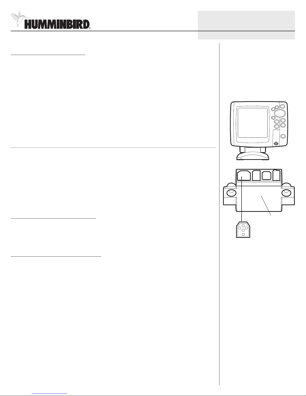
1. Access your Transducer cable and insert the Transducer cable connector into the Unit Switch connector until you
hear it click into place. efer to the Connect ng the Control Heads to the Sw tch and the Transducer
illustration on the following page for guidance.
To connect the control heads to the Un t Sw tch:
1. Insert the cable connectors from the Unit Switch through the T2 slots (transducer slots) on the connector holders.
Then reattach the connector holders, if necessary.
CAUTION: The slot for the connector is keyed to prevent reversed installation, so do not force the connector into the holder.
See your control head installation uide for additional information.
700 SERIES™ NOTE: If you are installin the Speed Sensor accessory (optional), insert the Sonar/Speed Y-Cable connector
into the T2 slot on the connector holder. Then, connect the transducer connector and speed sensor connector to the
correspondin connectors on the Y-Cable. The Y-Cable requires a separate purchase. Contact our Customer Resource Center
for details at 1-800-633-1468 or visit our Web site at humm nb rd.com.
© 2011 Humminbird®, Eufaula AL, USA.
All rights reserved.
Insert ng the Cable Connector
Unit Switch
Cable Connector
Connector Holder
Un t Sw tch
2
531871-1_A

To connect the connector cl ps to the Un t Sw tch:
1. From underneath the console, plug the two connector clips from the switch assembly into the two outlets of the
Unit Switch.
NOTE: Connectin the connector clips to the Unit Switch does not require a specific order; either connector will work with
either outlet.
3. Connect ng the Power Cable
Connect the Unit Switch power cable to the boat’s fuse panel (usually located near the console). If you must
connect to a battery, connect to a battery switch (not included).
1a. If a fuse terminal is available, use crimp-on type electrical connectors (not included) that match the terminal on
the fuse panel. Attach the black wire to ground (-), and the red wire to positive (+) 12 VDC power. Install a 3 amp
fuse (not included) for protection of the unit. Humminbird® is not responsible for over-voltage or over-current
failures.
or...
1b. If you need to wire the control head directly to a battery, obtain and install an inline fuse holder, a 3 amp fuse
(not included) for the protection of the unit, and a battery switch (not included). Install the battery switch using
the instructions provided with it.
NOTE: If you are unable to obtain a battery switch and are forced to connect the power cable directly to the battery, be
aware that this may cause a slow loss of power over time. See procedure five, Power ng Off.
NOTE: Humminbird® is not responsible for over-volta e or over-current failures. The control head must have adequate
protection throu h the proper selection and installation of a 3 amp fuse.
2. Secure the cables with cable ties (optional).
Your Unit Switch is now ready for operation.
2
1
Connect ng the Control Heads to the Sw tch and the Transducer
Cable Connector
Control Head Control Head
Cable Connector
Unit
Switch
Route connector to
the transducer
© 2011 Humminbird®, Eufaula AL, USA.
All rights reserved.
Connect ng to a Fuse Panel
Un t Sw tch
3
531871-1_A
Connect ng the Connector Cl ps
to the Un t Sw tch
Connector Clips
Switch

© 2011 Humminbird®, Eufaula AL, USA.
All rights reserved.
Un t Sw tch
4
531871-1_A
4. Sw tch ng Between Un ts
Perform the following procedures to alternate between the control heads connected to your Unit Switch:
1. Make sure both control heads are powered on.
2. Press the Unit Switch to engage the desired control head.
5. Power ng Off
It is important to make sure all accessories (switches, control heads, etc.) are powered off in order to avoid possibly
draining the battery. To make sure your Unit Switch is disengaged, follow the steps below.
If your Un t Sw tch s connected to the fuse panel,
1. Power off your boat to disengage the switch.
If your Un t Sw tch s connected to a battery sw tch,
1. Turn the dial of the battery switch to the OFF position.
If your Un t Sw tch s connected d rectly to a battery,
1. Power off your boat.
2. emove the Unit Switch wires from the battery.
Table of contents
Other Humminbird Switch manuals
Popular Switch manuals by other brands

NETGEAR
NETGEAR GS316P user manual

Endress+Hauser
Endress+Hauser IO-Link Ceraphant PTC31B operating instructions

Eaton
Eaton ZV-L1/N Series Instruction leaflet

CAMBRIONIX
CAMBRIONIX PP15S user manual

Zte
Zte ZXR10 3928A Hardware installation manual

Inscape Data
Inscape Data LinkPower LPS1800 Series user manual