Hummingbird Century User manual

The Hummingbird is the perfect electric helicopter for indoor flying and
calm days at the park. Open the box, and be flying in under two hours.At
justover9ounces,the Hummingbird willflyfor7- 10 minutesonthe7cell
NiMHbattery.
CENTURY
Itemsneededtoflythehummingbird
1xRadiotransmitter(minimum4channels)
1xReceiver(minimum4channels) CN2032
2xMicro servos CN2023
1xCenturymicrogyro CN2022E
1xHummingboardmixer/spdcontrol CNE052
1xBattery(8.4 V) CNE050
1xWallcharger(8.4V) CNE051
Important: Please Read the following,
This instruction manual will cover installation of the electronic components for your Hummingbird heli. WARNING: This is not a toy it is a
precision machine requiring proper setup and operation as improper setup or neglect can be dangerous to the operator. If you feel doubt as
to your ability or level of skill please seek professional assistance. As the manufacturer we assume no liasbility for the use of this product.
1.) Servo Mounting 2.) Receiver & Gyro
Mounting
3.) Rotor Head & Servo Linkage 4.) Bird Seed 8.4V 600MAH NiMh Battery
Provided
servo tape is
pre segmented
for the amount
used per servo.
Use the photo
provided to mount
the servos securely. The
helicopter frame has two
servo mounting positions
marked as pictured. The aileron servo mounts on the front of the
main frame. The elevator servo is mounted on the side of the frame
also pictured.
Aileron servo
Elevator servo
Mount the micro gyro on the rear with
the Century label reading upwards.
Using the servo
tape, Receiver
andmixer board
fit well into or on
top of the frame
case.
<Front-Rear>
Turn the radio on with all sticks and
trims centered. Use servo horns that
have a hole 10-12mm out from the
servo pivot center and place it
as pictured (parallel to
swashplate and frame).
Verify also that paddles,
swashplate & servo horns are
parallel to each other and also
90 degrees to the main shaft.
The servo horns may need
to be cut to avoid contact
with the canopy or frame
during movement.
Connectthe battery pack
to the charger for 1.5
hours or until very
warm to the touch.
(battery is NiMH and
comespartially charged. Do
not overcharge. Do not
completely drain a NiMH battery)
!ATTENTION:DONOTPINCHOR
SQUEEZEBATTERYENDS!Applying
pressure to ends may cause a short
destroying the battery.
BirdSeed
8.4V600mAh
Battery
[#CNE050]
Century Hummingbird
Instructions
Frame case

Insert the battery into position by sliding the battery
holdersalong thehorizontal railsto clampin place.Press
the rubber stoppers to secure the top and the rubber
band at the bottom. Pickup the Hummingbird by the
flybar and position the battery until the helicopter hangs
level or slightly nose heavy.
TheHummingBird Mixer &Speed Control isa microprocessorelectronic controller formicro electric helicoptersthat useseparatedirect current
motors for the main and tail rotor systems. The control board provides all the power for the electric motors, the radio equipment and performs
automaticmixingof thetailrotor tothemain rotor.
5.) Battery mounting & Gyro Connection
6.) Mixer & Speed Control
Connect the Throttle lead to the throttle channel on the receiver and the Rudder lead to the gyroscope. Do not connect a separate receiver battery to the
receiver, this will damage the Hummingboard. The Hummingboard has a BEC circuit to supply power to the receiver, gyro and servos.
8.) Channel Map by Radio
JR Futaba Hitec Airtronics
Aileron (move left & right) CH2 CH1 CH1 CH2
Elevator (move front & back) CH3 CH2 CH2 CH1
Throttle (go up & down) CH1 CH3 CH3 CH3
Rudder (turn left & right) CH4 CH4 CH4 CH4
The following are for the Century (CN2032) micro receiver, if you are
using a different receiver the assignments may change!
JR Futaba Hitec Airtronics Z
red to red red to red red to red red to red
brown to brown brown to black brown to black brown to black
orange to orange orange to white orange to yellow orange to white
Radio Connector Type
7.) Servo Wires
*Note orange signal wires are
to be installed facing each
other for the gyro only!
Warning: In the event of a crash immediately put the throttle in the lowest position. If the throttle is up and the blades (main or tail) are unable to
move due to an obstruction power will overflow to the mixer board and it may damage the hummingboard. This isnot covered under waranty.
8a.) Example Electronics Setup (Shows connections for Hitec Laser 4)
Negative (-)
Positive (+)
Signal (s)
Press the tail motor and main motor
connectors to the board, note that the
two red wires are beside each other when
connected to the board as marked by
positive and negative indicators. *Note orange signal
wires are to be installed
facing each other for
the gyro only!
AileronServo
(ch. 1) CN2023
Elevator Servo
(ch. 2) CN2023
Mixer Board
CNE052
Bird Seed Battery
CNE050
Micro Gyro
CN2022E
Main Motor
CNE010
Tail Motor
CNE019 Century
Micro
Receiver
CN2032
Aileron
Elevator
Throttle
Rudder
Not used
Not used
For Hitec

Turn the transmitter on first. While making the battery connection, ensure that the rotor blades will not touch yourself or anything on the work
surface.After the battery is connected, wait for 5 seconds for the control board and gyro to initialize, the red LED on the gyro will stop blinking.
If the throttle stick in not at the lowest position, the LED will remain solid red. The LED must change to green to start the motors. While firmly
holding the landing skids, slowly lift the throttle stick to turn the main blades slowly, stopping at half stick (50% power). If the blades do not turn
and the LED is red, lower the throttle stick, disconnect the battery and change the position of the Servo Reversing function for the throttle channel
on the radio. Repeat the procedure. If the LED blinks from red to green there is no signal from the radio.
During regular operation the Hummingboard will remain solid green but as the battery starts to run out and the voltage drops the helicopter will simply
descend. At this time it is best to land immediately.
On helicopter radios that have revolution mixing, either inhibit the function or set the revolution mixing amounts to 0 (zero) percentage.Also
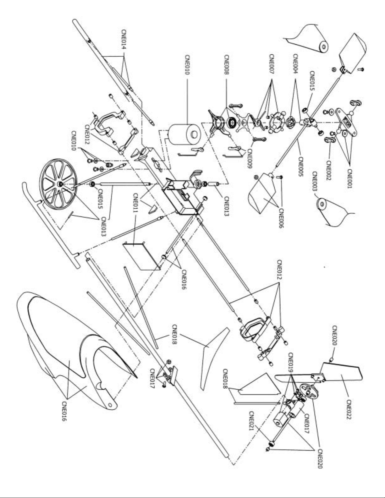
remove any rudder offsets, or tail curves if available on the radio. The Hummingboard is designed to automatically add tail rotor into the main rotor
to compensate for increased torque as the throttle is advanced.
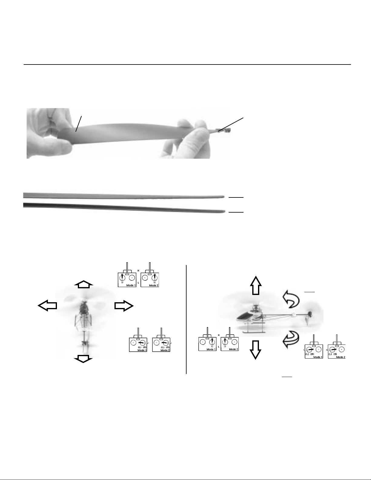
All flight trimming adjustments should be done on a flat, hard surface in a minimum area of 20 feet by 20 feet to ensure that trimming can be
completed. All helicopter trimming is always observed from the pilot home position. Position the Hummingbird 6 feet ahead of your position
with the nose forward. When observing reactions from the helicopter, always think in terms of which direction the nose moves. Never be
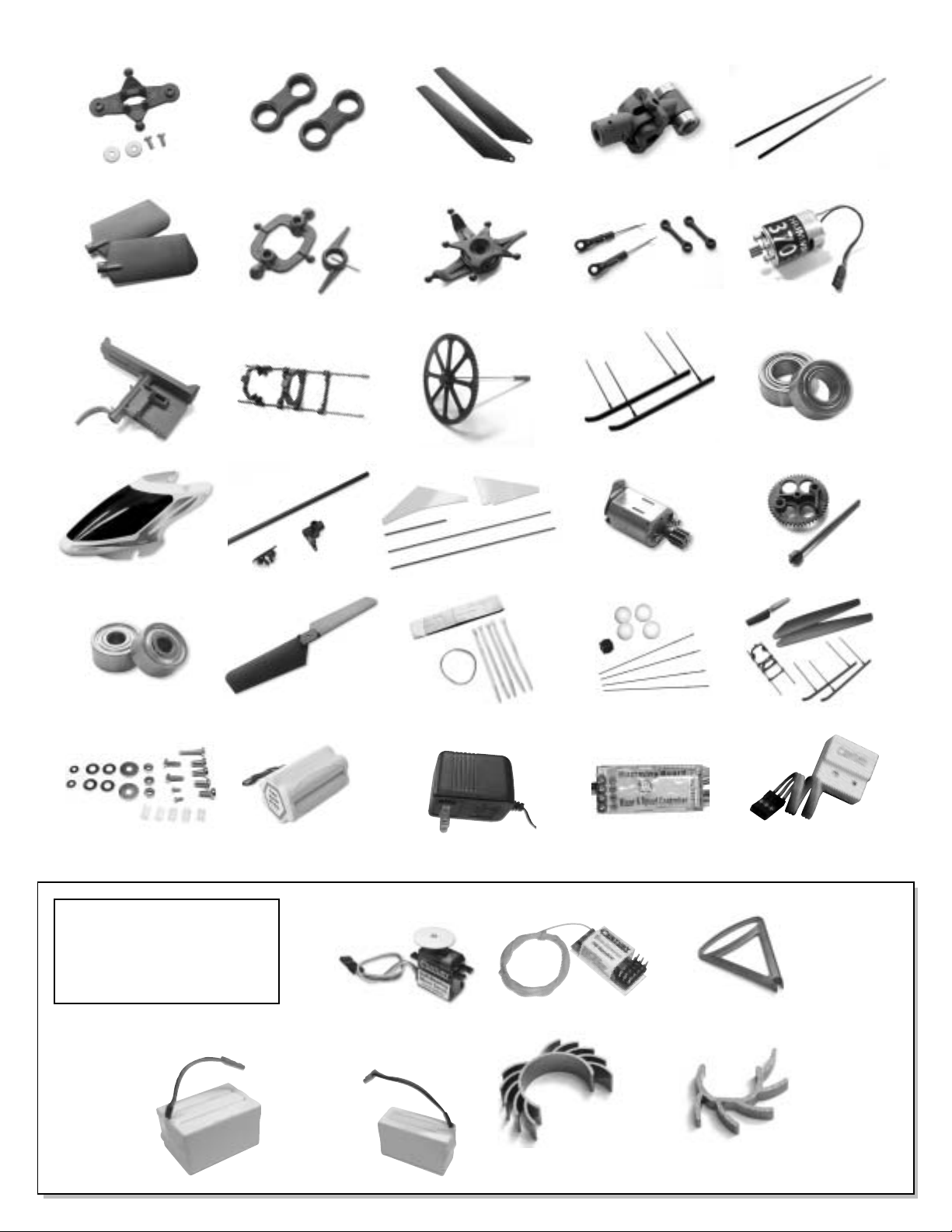
concerned with the tail, and never watch the tail. It is recommended to use optional training gear, #CNE053 before trying to trim or fly the
model.
Rudder Setup - Turn the transmitter on. Insert your hand and hold the landing gear firmly while making the battery connection, ensuring
that the main and tail rotor blades will not touch yourself or anything on the testing surface. Move the helicopter to the testing position, 6
feet in front of yourself. Slowly raise the throttle until the main blades are slowly turning. Carefully add right rudder on the transmitter, and
observe that the nose of the helicopter turns to the right. If the helicopter turns to the left, reverse the rudder channel on the transmitter.
Gyro Setup - Gyro gain is preset. Insert your hand and hold the landing gear firmly while making the battery connection, ensuring that the
main and tail rotor blades will not touch yourself or anything on the testing surface. Wait 5 seconds after power on to initialize the gyro
(blinking green LED goes solid), do not move the helicopter during this time. Verify that when the rudder stick is moved to the right the nose
rotates to the right, the throttle stick may need to be raised slightly to activate the electric motors. Holding the tail boom at the back of the
frame from below jerk the nose to the left, the tail rotor should start rotating moving the nose right. This may take a few tries to verify gyro is
in the correct direction. If the helicopter is powered up with the gyro reversed, the helicopter will spin uncontrollably. To reverse the gyro
direction, reinstall the gyro upside down. Repeat the gyro setup test. (more on next page)
Q: Everything is on and connected why don’t the rotors turn? A: The throttle trim may be set too high try moving the trim to the lowest point.
Your gyro may be installed incorrectly make sure the the order of wires is as shown in steps 5 and 9. Also your throttle channel may be reversed.
Q:Why does the Helicopter spin like a top? A: It’s possible that the rudder channel on your radio is reversed or your gyro is installed upside
down. please see step 2 for best mounting location. Again check the connections to the receiver to make sure connections are correct. If the
problem persists take a look at the direction the tail motor turns. the curved portion of the tail rotor should move forward being the “leading edge”
if this is not the case please check the polarity of the motor’s connection to the mixer board.
Q: Why is there vibration?A: The main blades may be out of track. Check out step 15 on the next page. The main shaft may be bent. This can be
difficult to notice when the blades are not moving. a bent main shaft can be caused in a crash or a hard blade strike. Vibration can also result from
any loosely connected components such as the battery tray or the landing gear. Make sure to secure them using the provided mini rubber stoppers
and be sure to check the frame and flybar every time you crash or have a hard landing.
Q: Why won’t the helicopter come off of the ground? A: be sure that the gear mesh on the main motor moves smoothly and that the battery is
fully charged. Do not fully discharge a NiMH type battery as it will lose it’s capacity memory. If you don’t think it’s the battery it’s possible
that the centrifugal force created by the spinning blades has flattened out the curve in the rotor blades. Carefully bend the plastic back in to a curve
trying to keep the curve of both blades as equal as possible.
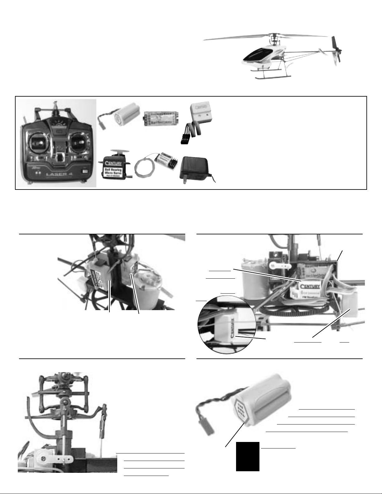
9.) Helicopter Radios
10.) The First Flight
11.) Common Questions & Answers
13.) Transmitter Adjustments
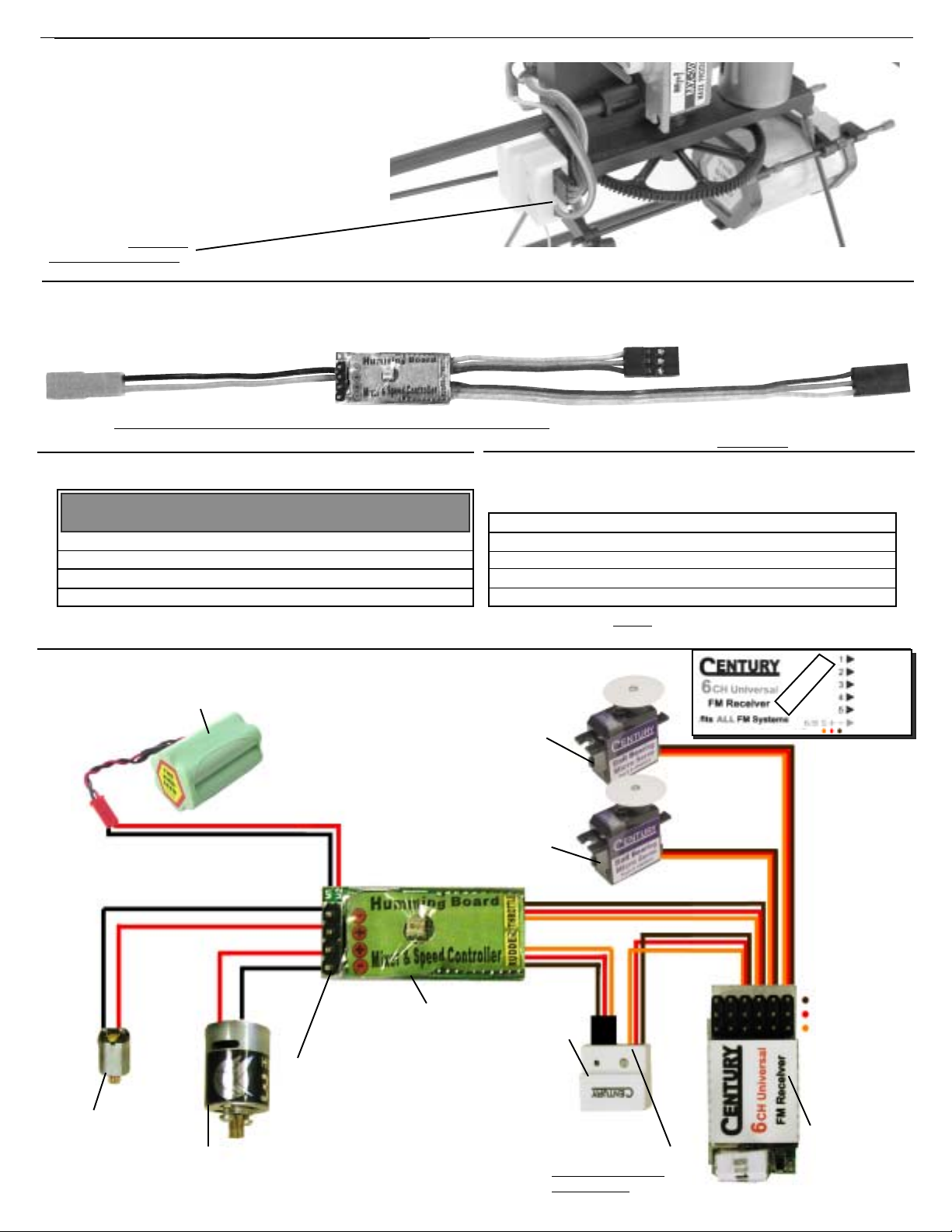
The last important wire to route is the antenna, it is vital that
the antenna wire is isolated from all the other wires and motors
on the helicopter. Install the antenna along the bottom of the
frame, making sure it does not touch another wire and that it
does not cross itself. Run the end of the antenna out to the
horizontal fin, attaching it with a small elastic or piece of tape.
IMPORTANT NOTES:
-JR radio equipment. On JR radios, the throttle channel needs to be reversed. -
When using radio equipment that is different than shown in the manual, you will
need to reposition the receiver and the Hummingboard to make all the connec-
tions.- HummingBoard. It is normal on some radios to have the LED on the board
solid green at below half stick then change to solid red from half stick to full
power. This is normal operation. - JR receivers: The connectors on the
HummingBoard are square in design, when using an original JR receiver, two
edges need to be shaved (chamfered) to fit into the receiver.
12.) Antenna Mounting

Aileron & Elevator Setup - (continued from previous page) Turn the transmitter on. Insert your hand and hold the landing gear firmly while
making the battery connection. While looking at the swashplate, move the aileron stick to the right and verify that the swashplate tilts to the
right, when viewing the helicopter from the rear. Again, move the elevator stick forward and verify that the swashplate tilts forward. If any
channel is backwards, simply toggle the reversing switch on the transmitter.
BladeTracking and LiftAdjustment - If the transmitter throttle stick is at 1/2 power and the helicopter will not lift off the
ground, bend or twist the main blades slightly to increase the angle of attack of the blades and adjust both blades equally. This
will increase the blade pitch.
It is possible that after twisting or bending the blades that the blades may go out of track. When viewed from the side, there
appears to be two blades. To correct this decrease the pitch on blade Aand increase the pitch on blade B until only one blade
can be seen.Attaching a small piece of colored tape to the tip of one blade will make this easier.
Twist the blade tip upwards.
Carefully! While holding
the blade near
the rotorhead.
A
B
Both blades
should track in the
samelineA=B.
Move aileron
stick left, heli
moves left.
Move aileron stick
right, heli moves right.
Move throttle
stick upwards, heli
rises.
Move elevator stick forward, heli
moves forward.
Move elevator stick backwards, heli
moves backwards.
Move throttle
stick downwards,
heli decends.
Move rudder stick
left, nose moves
left.
Move rudder stick right,
nose moves right.
Control Movement - All trimming of the Hummingbird should be done one click or detent of the subtrims at a time until it will rise
without moving left, right, forward or backward at a location without wind. Some tail rotation is normal at lift off until it is
hovering. Start by lifting the Hummingbird 3-6 inches at a time to practice lift off and landing.
Your new equipment is warranted to the original purchaser against manufacturer defects in material and workmanship for 90 days from the date of
purchase. The warranty is limited to the original purchaser and is not transferable. This warranty does not apply to any unit which has been
improperly installed, mishandled, abused or damaged in a crash, or to any unit which has been opened, repaired or altered by any unauthorized
person. Under no circumstances will the buyer be entitled to consequential or incidental damages.
If the Hummingboard requires service and is within the warranty period, call for a return authorization # and include a copy of the original receipt.
Package the unit in a sturdy container and include full return address and description of damage. Send the parcel insured and postage prepaid, please
allow 8-12 weeks for service.
Non-warranty repairs- You will be advised on the repair cost, please allow 8-12 weeks for service.
Warranty
14.) Hummingbird Trimming
USA
USA USA USA

CNE001 CNE002 CNE003 CNE004 CNE005
CNE006 CNE007 CNE008 CNE009 CNE010
CNE011 CNE012 CNE013 CNE014 CNE015
CNE016 CNE017 CNE018 CNE019 CNE020
CNE021 CNE022 CNE023 CNE053 CNE054
CN2022E
CNE052
CNE051
CNE050
Main Rotor Yoke Rotor Head Links Main Blades (2) Rotor Hub & Bearings Flybar (2)
Flybar Paddles Seesaw & Timing Yoke Swashplate Cyclic Links & Rods MainMotor
Main Frame Battery Support Set Main Gear & Shaft Landing Gear Rotor Head Bearings
Canopy & Decal Tail Boom & Gearbox Fins & Boom Supports Tail Drive Motor Tail Gear & Shaft
Tail Bearings Tail Rotor Blades Tie Wraps, Tape & Band Trainer Pod Crash Kit
MicroGyro
Mixer Control Board
Charger
FM 6 Channel Micro
Receiver CN2032
Main Motor Heat Sink
CNE061
Lithium Ion Battery
1400mAh 11.1V
CNE058
Main Blade Holder
CNE059
Ball Bearing Micro Servo
CN2023
CNE057
Main Motor Heat Sink
CNE060
Lithium Ion Battery
700mAh 11.1V
Super
Light!
Battery
NewItems
AndOptions
CNE055
Fastener Set

Table of contents
Other Hummingbird Toy manuals