manuals.online logo
Brands
  1. Home
  2. •
  3. Brands
  4. •
  5. Hunter
  6. •
  7. Fan
  8. •
  9. Hunter 23869 User manual

Hunter 23869 User manual

Other manuals for 23869

2

Other Hunter Fan manuals

Hunter Barrel 51549 User manual

Hunter

Hunter Barrel 51549 User manual

Hunter Sona User manual

Hunter

Hunter Sona User manual

Hunter 20430 User manual

Hunter

Hunter 20430 User manual

Hunter Winslow Manual

Hunter

Hunter Winslow Manual

Hunter 42637-01 Instruction manual

Hunter

Hunter 42637-01 Instruction manual

Hunter Windspan 59012 Instruction manual

Hunter

Hunter Windspan 59012 Instruction manual

Hunter 23860 Manual

Hunter

Hunter 23860 Manual

Hunter Warrant User manual

Hunter

Hunter Warrant User manual

Hunter 42753-01 Instruction manual

Hunter

Hunter 42753-01 Instruction manual

Hunter Augusta Instruction manual

Hunter

Hunter Augusta Instruction manual

Hunter Hardaway 50706 User manual

Hunter

Hunter Hardaway 50706 User manual

Hunter Hunter Ceiling Fan User manual

Hunter

Hunter Hunter Ceiling Fan User manual

Hunter 28672 Instruction Manual

Hunter

Hunter 28672 Instruction Manual

Hunter 81006 Manual

Hunter

Hunter 81006 Manual

Hunter 41923 User manual

Hunter

Hunter 41923 User manual

Hunter WELLESLEY 82007 User manual

Hunter

Hunter WELLESLEY 82007 User manual

Hunter 50393 User manual

Hunter

Hunter 50393 User manual

Hunter 20430 Manual

Hunter

Hunter 20430 Manual

Hunter 28685 Manual

Hunter

Hunter 28685 Manual

Hunter 90405 User manual

Hunter

Hunter 90405 User manual

Hunter 23781 Instruction manual

Hunter

Hunter 23781 Instruction manual

Hunter Baseball 23252 User manual

Hunter

Hunter Baseball 23252 User manual

Hunter CENTURY 90121 User manual

Hunter

Hunter CENTURY 90121 User manual

Hunter Kingsbridge Instruction manual

Hunter

Hunter Kingsbridge Instruction manual

Popular Fan manuals by other brands

Minka Group minkaAire Wave F843 instruction manual

Minka Group

Minka Group minkaAire Wave F843 instruction manual

Airflow Adroit DV50 instruction manual

Airflow

Airflow Adroit DV50 instruction manual

Vornado 270 Series owner's guide

Vornado

Vornado 270 Series owner's guide

comfort air TH-10D instruction manual

comfort air

comfort air TH-10D instruction manual

Livoo DOM386 instruction manual

Livoo

Livoo DOM386 instruction manual

Holmes BLIZZARD HAOF-90 owner's guide

Holmes

Holmes BLIZZARD HAOF-90 owner's guide

Taurus GRECO 16 ELEGANCE manual

Taurus

Taurus GRECO 16 ELEGANCE manual

Quorum PINNACLE installation instructions

Quorum

Quorum PINNACLE installation instructions

Monte Carlo Fan Company 3DIR58RBD-V1 Owner's guide and installation manual

Monte Carlo Fan Company

Monte Carlo Fan Company 3DIR58RBD-V1 Owner's guide and installation manual

Craftmade UH52 installation guide

Craftmade

Craftmade UH52 installation guide

Jocel JVA030658 instruction manual

Jocel

Jocel JVA030658 instruction manual

MIKA MFB1211/GR user manual

MIKA

MIKA MFB1211/GR user manual

Harbor Breeze RLG52NWZ5L manual

Harbor Breeze

Harbor Breeze RLG52NWZ5L manual

Allen + Roth L1405 instruction manual

Allen + Roth

Allen + Roth L1405 instruction manual

ViM KUBAIR F400 ECOWATT Technical manual

ViM

ViM KUBAIR F400 ECOWATT Technical manual

HIDRIA R10R-56LPS-ES50B-04C10 user guide

HIDRIA

HIDRIA R10R-56LPS-ES50B-04C10 user guide

BLAUBERG Ventilatoren CENTRO-M 100 L user manual

BLAUBERG Ventilatoren

BLAUBERG Ventilatoren CENTRO-M 100 L user manual

Triangle Engineering HEAT BUSTER SPL Series owner's manual

Triangle Engineering

Triangle Engineering HEAT BUSTER SPL Series owner's manual

manuals.online logo
manuals.online logoBrands
  • About & Mission
  • Contact us
  • Privacy Policy
  • Terms and Conditions

Copyright 2025 Manuals.Online. All Rights Reserved.

For Your Records and Warranty
Assistance
Model Name: ____________________
Catalog/Model No.: _______________
Serial No.: _______________________
Date Purchased: __________________
Where Purchased: ________________
For reference also attach your receipt or a
copy of your receipt to the manual. TYPE A Models
installation and
operation manual
for Hunter
Ceiling Fans
42825-01 • 05/17/07
2
42825-01 • 05/17/07 • Hunter Fan Company
Table of Contents
1 • Getting Ready........................................ 4
2 • Installing the Ceiling Plate ................ 5
3 • Assembling the Fan............................. 6
4 • Hanging and Wiring the Fan............. 7
5 • Installing the Canopy and Canopy
Trim Ring .................................................. 8
6 • Assembling the Blades ....................... 9
7 • Completing Your Installation With
or Without a Light Fixture ................10
8 • Operating and Cleaning
Your Ceiling Fan ...................................14
9 • Troubleshooting..................................15
© 2007 Hunter Fan Company
Your new Hunter®ceiling fan is an addition to your home or
oce that will provide comfort and performance for many years.
This installation and operation manual gives you complete
instructions for installing and operating your fan.
We are proud of our work. We appreciate the opportunity to
supply you with the best ceiling fan available anywhere in the
world.
Before installing your fan, for your records and warranty
assistance, record information from the carton and Hunter
nameplate label (located on the top of the fan motor housing).
Cautions and Warnings
•READ THIS ENTIRE MANUAL CAREFULLY BEFORE BEGINNING
INSTALLATION. SAVE THESE INSTRUCTIONS.
•Use only Hunter replacement parts.
•To reduce the risk of personal injury, attach the fan directly
to the support structure of the building according to these
instructions, and use only the hardware supplied.
•To avoid possible electrical shock, before installing your fan,
disconnect the power by turning o the circuit breakers to the
outlet box and associated wall switch location. If you cannot
lock the circuit breakers in the o position, securely fasten a
prominent warning device, such as a tag, to the service panel.
•All wiring must be in accordance with national and local
electrical codes and ANSI/NFPA 70. If you are unfamiliar with
wiring, use a qualied electrician.
•To reduce the risk of personal injury, do not bend the blade
attachment system when installing, balancing, or cleaning the
fan. Never insert foreign objects between rotating fan blades.
•To reduce the risk of re, electrical shock, or motor damage,
do not use a solid-state speed control with this fan. Use only
Hunter speed controls.
Welcome

3
42825-01 • 05/17/07 • Hunter Fan Company
Mounting and Optional Accessories
Understanding Mounting
Hunter’s patented mounting system provides you maximum ease in
installing your fan.This fan was designed to be mounted only on at
ceilings and can be used on ceilings less than 8 feet high.
Considering Optional Accessories
ConsiderusingHunter’soptionalaccessories,includingawall-mounted
or remote speed control. To install and use the accessories, follow
theinstructionsincludedwitheach product. Forquietand optimum
performance of your Hunter fan, use only Hunter speed controls.
Low Prole Mounting ts close to the
ceiling, recommended for ceilings less
than 8 feet high
Support Brace
Low Prole
Mounting
Style
Ceiling
Outlet Box
CAUTION: To reduce the risk of
personal injury, attach the fan directly
tothesupportstructureofthebuilding
accordingtotheseinstructions,anduse
only the hardware supplied.
4
42825-01 • 05/17/07 • Hunter Fan Company
1 • Getting Ready
To install a ceiling fan, be sure you can do the following:
•Locate the ceiling joist or other suitable support in ceiling.
•Drill holes for and install wood screws.
•Identify and connect electrical wires.
•Lift 40 pounds.
If you need help installing the fan, your Hunter fan dealer can direct
you to a licensed installer or electrician.
Gathering the Tools
You will need the following tools for installing the fan:
•Electric drill with 9/64” bit
•Standard screwdriver (magnetic tip recommended)
•Phillips-head screwdriver (magnetic tip recommended)
•Wrench or pliers
•Ladder (height dependent upon installation site)
Checking Your Fan Parts
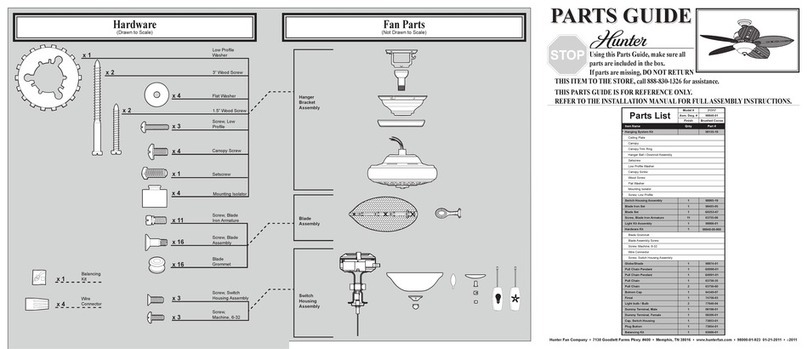
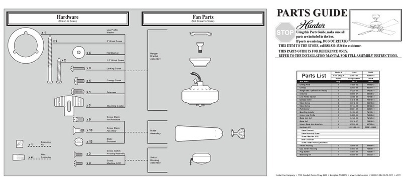
Carefully unpack your fan to avoid damage to the fan parts. Refer to
theincludedPartsGuide.Checkforanyshippingdamagetothemotor
orfanblades.Ifanypartsaremissingordamaged,contactyourHunter
dealerorcallHunterTechnicalSupportDepartmentat888-830-1326.
Preparing the Fan Site
Before you begin installing the fan, follow all the instructions in
the pullout sheet called “Preparing the Fan Site.” Proper ceiling fan
location and attachment to the building structure are essential for
safety, reliable operation, maximum eciency, and energy savings.
Installing Multiple Fans?
If you are installing more than
onefan,keepthefanbladesand
bladeirons(ifapplicable)insets,
as they were shipped.
5
42825-01 • 05/17/07 • Hunter Fan Company
2 • Installing the Hanger Bracket
CAUTION: To avoid possible electrical shock, before installing your
fan, disconnect the power by turning o the circuit breakers to the
outlet box and associated wall switch location. If you cannot lock
the circuit breakers in the o position, securely fasten a prominent
warning device, such as a tag, to the service panel.
2-1. Drill two pilot holes into the wood support structure through
the outermost holes in the outlet box. The pilot holes should
be 9/64” in diameter.
2-2. Partially install two canopy screws in the holes on each end
of the hanger bracket, as shown in the gure to the right.
2-3. Your fan comes with four mounting isolators. Position the
isolators between the hanger bracket and ceiling by inserting
the raised areas on each isolator into the holes in the hanger
bracket.
2-4. Thread the lead wires from the outlet box down through the
hole in the middle of the hanger bracket.
2-5. Align the slotted holes in the hanger bracket with the pilot
holes you drilled in the wood support structure.
Note: The isolators should be ush against the ceiling.
2-6. Place a at washer on each of the two 3”wood screws and pass
the screws through the slotted holes in the hanger bracket into
the pilot holes you drilled.
Tighten the screws into the 9/64”pilot holes; do not use
lubricants on the screws. Do not over tighten.
Step 2-2
Flat Washer
3”Wood Screw
Steps 2-4 – 2-6
Hanger
Bracket
Step 2-3
CanopyScrew
Canopy
Screw
Isolator
6
42825-01 • 05/17/07 • Hunter Fan Company
3 • Assembling and Hanging the Fan
Step 3-2
#8-32 x 1” Screw
Green
Ground Wire
3-1. Position the square hanger so that the green ground wire
attached to the square faces out of the large opening in the
metal bracket.
3-2. Holding the wires out of the way, lift the motor assembly and
place the square hanger into the opening in the ceiling plate.
WARNING: Make sure the square hanger can not rotate in the
metal bracket. Failure to do so could result in the fan falling.
3-3. Install two locking screws through the holes in the side of the
metal bracket to secure the square hanger.
Step 3-1
Motor
Assembly
Square
Hanger
Step 3-3
Locking Screw
Green
Ground Wire
7
42825-01 • 05/17/07 • Hunter Fan Company
4 •Wiring the Fan
All wiring must be in accordance with national and local electrical
codes and ANSI/NFPA 70. If you are unfamiliar with wiring, use a
qualied electrician.
4-1. Disconnect the power by turning o the circuit breakers to the
outlet box and associated wall switch location.
4-2.Toconnectthewires,holdthebaremetalleadstogetherandplacea
wire nut over them, then twist clockwise until tight.
CAUTION: Be sure no bare wire or wire strands are visible after
making connections.
4-3. Connect the wires as follows:
• Thegreenorbaregroundwirefromtheceilingtothegreenground
wire from the ceiling plate and the green ground wire from the fan
• The white (common) power wire from the ceiling to the white wire
from the fan
• Theblackpowerwirefromtheceilingtotheblackwirefromthefan
• The black/white wire from the fan to the black/white wire from
the ceiling.
4-4.Pushallwiresandwirenuts back throughtheceilingplatehole into
the outlet box.
Step 4-3
Wire
Connector
8
42825-01 • 05/17/07 • Hunter Fan Company
4 •Wiring the Fan
All wiring must be in accordance with national and local electrical
codes and ANSI/NFPA 70. If you are unfamiliar with wiring, use a
qualied electrician.
Wallswitchesarenotincluded.Selectanacceptablegeneral-useswitch
in accordance with national and local electrical codes.
4-1. Before attempting installation, make sure the power is still o.
4-2. Toconnectthewires,holdthebaremetalleadstogetherandplace
awirenutoverthem,thentwistclockwiseuntiltight.Forallthese
connections use the wire nuts provided.
4-3. Connect the bare or green ground wire (grounded) from the
ceilingtothegreengroundwire(grounded)fromtheceilingplate
and the green ground wire from the fan.
4-4. Connect the white wire (ungrounded) from the ceiling to the
white wire (ungrounded) from the fan.
4-5. Connect the remaining wires as follows:
Dual Switch Wiring:
• Theblackwire(ungrounded)fromtheceilingtotheblackwire
(ungrounded) from the fan
• The black/white wire (ungrounded) from the fan to the wire
(ungrounded) for the wall switch
Single Switch Wiring:
• The black wire (ungrounded) from the ceiling to the black
(ungrounded) and the black/white wire (ungrounded) from
the fan
CAUTION: Be sure no bare wire or wire strands are visible after
making connections.
4-6. Turnthesplicesupwardandpushthemcarefullybackthroughthe
ceiling plate into the outlet box.
4-7. Spread the wires apart, with the grounded wires on one side of
theoutletboxandtheungroundedwiresontheothersideofthe
outlet box.
Wire
Connector
9
42825-01 • 05/17/07 • Hunter Fan Company
5 • Installing the Motor Housing
5-1. Place the fan housing over the motor.
5-2. Align the keyholes in the fan housing with the two partially
installed canopy screws in the hanger bracket. Rotate the fan
housingtosituatethescrewsinthenarrowendsofthekeyholes.
5-3. Installthetworemainingcanopyscrewsintotheholesinthefan
housingandintothehangerbracket.Securelytightenallscrews.
Canopy
Screw
Step 5-1
Motor
Step 5-3
Fan Housing
10
42825-01 • 05/17/07 • Hunter Fan Company
6 • Assembling the Blades
Hunterfansuseseveralstylesoffanbladeirons(bracketsthatholdthe
blade to the fan).
6-1. Yourfanmayincludebladegrommets.Ifyourfanhasgrommets,
insert them by hand into the holes on the blades.
6-2. Attach each blade to a blade iron using three blade assembly
screws.Ifyouusedgrommets,thebladesmayappearslightlyloose
after screws are tightened. This is normal.
6-3. Removetheblademountingscrewsandrubbershippingbumpers
fromthemotor.Note:Someblademountingscrewsareinstalled
in the motor to secure shipping blocks.
6-4. For each blade, insert one blade mounting screw through the
blade iron, and attach lightly to the fan. Insert the second blade
mounting screw, then securely tighten both mounting screws.
Step 6-1 (Detail)
Blade Assembly
Screws
Use with grommet
Use without grommet
Grommet
Blade
Mounting
Screw
Steps 6-1 – 6-2
Step 6-4