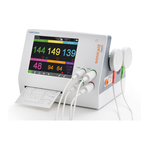
Huntleigh SONICAID FREEDOM SF1-EUR User manual

SF1-EUR

Contents
1. Introduction........................................................................4
1.1 Indications of Use..................................................................................4
1.2 Contraindications ..................................................................................4
1.3 Unpacking / Preliminary Checks..........................................................5
2. Safety .................................................................................6
2.1 WARNINGS.............................................................................................7
3. Product Information ...........................................................9
3.1 System Overview...................................................................................9
3.2 The Receiver Unit...................................................................................10
3.2.1 Operation................................................................................................................10
3.2.2 Front Panel Indicators............................................................................................11
3.2.3 Rear Panel controls and Indicators........................................................................13
3.3 The Transducers....................................................................................14
3.4 Product Labelling...................................................................................16
4. Setup...................................................................................17
4.1 Receiver Connection.............................................................................17
4.2 Testing the Basic Functions.................................................................17
5. Operation ...........................................................................19
5.1 Getting Started.......................................................................................19
5.2 Application of the Transducers............................................................19
5.3 Ambulatory Monitoring .........................................................................21
5.4 Water Birth Monitoring..........................................................................21
5.5 Ending Monitoring / Switching Off.......................................................22
6. Care and Cleaning ..............................................................23
6.1 General Care...........................................................................................23
6.2 Cleaning and Disinfecting.....................................................................24
6.2.1 Transducers ...........................................................................................................24
6.2.2 Receiver Unit..........................................................................................................26
7. Maintenance.......................................................................27
7.1 Mechanical Inspection ..........................................................................27
7.2 Corrective Maintenance ........................................................................27
7.3 Charging Transducer Batteries............................................................27
7.4 Transducer Battery Replacement.........................................................27
7.5 Servicing.................................................................................................27

3
Table of Contents
8. Trouble Shooting ................................................................28
8.1 Manually Switching off the Transducers.............................................30
8.2 Re-enabling Transducers......................................................................31
8.3 Changing the RF-channel .....................................................................32
9. Specifications ....................................................................33
9.1 Equipment Classification .....................................................................33
9.2 Receiver Unit (SF1-EUR / SF1-SL)........................................................33
9.3 US-Transducer (SF1-US).......................................................................34
9.4 TOCO-Transducer (SF1-TOCO) ...........................................................34
9.5 Environmental........................................................................................34
9.6 Directives and Standards Compliance*...............................................35
9.7 Recommended Consumables & Accessories* ..................................35
10. Electromagnetic Compatibility ........................................36
11. Ultrasound Safety Considerations ...................................37
12. End of Life Disposal..........................................................41
13. Warranty & Service ..........................................................42

4
Introduction
1. Introduction
1.1 Indications of Use
The Sonicaid™ Freedom (‘Freedom’) is a wireless fetal monitoring system
for the monitoring of fetal heart movement and maternal contractions
during intrapartum and antepartum periods of pregnancy.
It is an optional accessory for use with Huntleigh Healthcare Limited’s
approved Fetal Monitors such as Sonicaid FM820, FM830 Encore Fetal
Monitors (‘FM800E Monitors’) and Team Monitors (Excluding TeamIP) as
an alternative to their wired transducers. When connected to a suitably
approved Monitor, the system monitors:
• Uterine activity by using an external, pressure-sensitive TOCO
transducer, and
• Fetal heart rate (FHR) by pulsed Doppler ultrasound using an external
Ultrasound transducer.
Freedom is suitable for use in clinical and hospital facilities for use on
pregnant woman. The transducers are water tight allowing pregnant
women to be monitored while they are mobile, stationary or in a bath or
shower environment.
This system should only be used by, or under the supervision of, a
licensed physician or other health practitioner who is trained in the use of
FHR monitors.
1.2 Contraindications
Sonicaid™ Freedom is not intended for use with patients fitted
with cardiac pacemakers, during defibrillation, while undergoing
surgery, or while MRI scanning is taking place.
Sonicaid™ Freedom must not be used in intensive care units or
operating rooms.

5
Introduction
1.3 Unpacking / Preliminary Checks
Contents (supplied with each system)
Item Item Item
1 x Sonicaid™ Freedom
Receiver Unit
(WMTS: SF1-SL or
ISM: SF1-EUR)
1 x Instructions for
Use CD 1 x Receiving Antenna
(Gainflex - GF430TNC)
1 x Ultrasound Transducer
(SF1-US) 1 x Interface Cable 2 x Transducer Clips
1 x TOCO Transducer
(SF1-TOCO) 1 x Mains Lead 1 x FM800E to
Sonicaid™ Freedom
Fixing Kit
Delivery Inspection
Huntleigh takes every precaution to ensure that goods reach you in perfect
condition. However, accidental damage can occur in transit and storage.
For this reason we recommend that a thorough visual inspection is made
immediately the unit is received. Should any damage be evident or any parts
missing, ensure that Huntleigh or your distributor is informed at once.
Storage
Should the unit not be required for immediate use, it should be re-sealed into
its original packing after carrying out the initial delivery inspection, and stored
under covered conditions at a temperature between -10°C to +50°C, and
relative humidity of 10% to 93% non-condensing.

6
Safety
2. Safety
Before using this equipment, please study this manual
carefully and familiarise yourself with the receiver,
transducers, the indicators and operation. Ensure that
each user fully understands the safety and operation of the
unit, as mis-use may cause harm to the user or patient, or
damage to the product.
Ultrasound monitoring should be performed in accordance
with current guidelines. The ALARA guideline (AIUM)
recommends that ultrasound exposure should be kept As
Low As Reasonably Achievable.
General Warning / Residual risks are those risks that require
a warning or caution to be entered into this manual. They are
identified by the proximity of this symbol.
This device may only be used in combination with one of
Huntleigh Heathcare Ltd's ('Huntleigh') Sonicaid™ FM800E or
Team fetal monitor range (excluding TeamIP). The FM800E
monitor range includes model numbers FM820E and FM830E.
Please keep these Instructions for Use to hand for future reference.
Refer to the appropriate Fetal Monitor Instructions for Use for details of
operation and handling.
Refer to Section 3.4 of this manual for definitions of all symbols used on
product labelling.

7
Safety
2.1 WARNINGS
The Sonicaid™ Freedom should only be used by personnel
familiar with the operation of electro-medical equipment,
especially for electronic monitoring of the fetal heart rate.
A possible explosion hazard exists if used in the presence of
flammable anaesthetics.
The Sonicaid™ Freedom should not be used at temperatures
lower than 10 or higher than 40 degrees centigrade.
Do not mount the unit directly above the patient. Locate the unit
so that it will not cause harm should it fall.
Do not operate the unit from the mains supply if the mains cable
is damaged.
Do not immerse any portion of the receiver unit in water or other
liquids. The transducers are watertight and may be used in water
(IPX8 - TRANSDUCERS ONLY).
If there is any damage to the transducer housings, do not use
the transducer under water. Refer the transducer to Huntleigh
Healthcare qualified service personnel for repair.
The transducers are protected from damage if dropped. Never
use the transducer without its protective bumper. It can be
removed for cleaning in accordance with the Cleaning and
Disinfection Procedure in Section 6.
If this product is connected to another item of electrical
equipment, it is important that the system is fully compliant with
EN60601-1.
The device is generating RF-radiation. It is designed for use in
hospitals and other clinical settings, also outside of shielded
areas. As in other medical electrical devices, fixed and mobile
RF-communication devices may disrupt the performance of the
Sonicaid™ Freedom.
The telemetry equipment is classified as IIb according to Medical
Devices Directive 93/42/EEC. The receiver unit is connected to
the AC line without a protective earth (Class 2). The line voltage
may be between 100 and 240V with 50 to 60Hz. The transducer
units are powered by safe current limited low voltage re-
chargeable batteries of 3.7V. Transducers are Class CF.

8
Safety
In case of a discharge of static electricity at the receiver,
the functions of the receiver may become disabled. Please
disconnect the mains lead for about 5 seconds.
To disconnect from the mains, the plug must be removed.
Always ensure that the plug is easily accessible.
The receiver unit should be plugged into the same mains supply
circuit as other equipment in use on the same patient.
Use only recommended accessories listed in this manual.
Do not modify this equipment without authorisation of the
manufacturer.

9
Product Information
3. Product Information
3.1 System Overview
Freedom consists of three components: the Ultrasound transducer (SF1-US),
the TOCO transducer (SF1-TOCO) and the Receiver (SF1-EUR or SF1-SL).
There are two receiver models operating at different radio frequencies for
different markets. "SF1-EUR" is for use in regions that use the ISM wireless
standard; "SF1-SL" is for use in regions that use the WMTS wireless standard.
When in use, the TOCO transducer sends signals to the US transducer, which
then transmits both signals to the Freedom receiver unit. The receiver converts
these signals into the required format for input to the attached Fetal Monitor
system. The system monitors two physiological parameters:
- Fetal Heart Rate
- Uterine activity
Key features:
• Transducers are small, light in weight and water tight
• Low voltage wireless transmission is safe for use in water
• No cables gives the patient greater freedom of movement in & out of bed
• The system is easy for the users to operate
• The transducers are powered by rechargeable Li-Ion batteries
• Batteries will automatically recharge when docked with the receiver
Transducers
The transducers contain radio frequency (RF) transmitters. Signals are
transmitted in an ISM or WMTS band according to location and local
regulations. The SF1-EUR (ISM) has 26 channels, and SF1-SL (WMTS) has
100 channels. The range depends on the local conditions. The exact range
of any telemetry system can only be determined by a field test. When the
US transducer is used under water the range will be reduced compared with
transmission in air.
During use the battery capacity of the transducers are monitored. The receiver
has a battery indicator for each transducer consisting of four green LEDs; four
LEDs indicating that the transducer is fully charged. When the battery becomes
discharged the transducer is automatically shut off.

10
Product Information
Receiver
The receiver has two docking areas for the TOCO and US transducers, three
sets of visual indicators (charging, battery level and transducer status) and the
antenna for receiving transmissions from the US transducer when in use. In
addition, the rear panel includes the receiving antenna, RF-Channel selector,
interface for connecting to the Fetal Monitor, and line voltage input for power.
The receiver and transducers have no buttons to operate. When identified
transducers are undocked, they are switched on automatically and the receiver
indicates the status of batteries and the quality of the incoming RF-signal. When
unidentified transducers are undocked, they are switched off.
To start monitoring, the transducers are undocked from the receiver and applied
to the patient. It is recommended that the US transducer be applied to the
patient first.
The TOCO-Transducer transmits its signal to the US-transducer. The US
transducer transmits both the US and TOCO signals to the receiver.
3.2 The Receiver Unit
3.2.1 Operation
The receiver does not have a mains switch. To turn on, connect the mains lead
from the rear mains input to mains supply. Always leave the receiver connected
to allow the transducers to be charged. If you want to switch off Freedom, dock
both transducers first, wait for charging indication, then disconnect the supply,
wait 10 seconds. All units are now switched off. All modules are turned on when
the receiver is powered again.
When power is applied with an ultrasound transducer docked in the charging
bay, it is automatically registered as belonging to this particular receiver
(referred to as "pairing" or "paired"). This ensures that, where multiple wireless
systems are being used in close proximity, there is no interference between
systems. Successful pairing is indicated by the charge position LED switching
on (not flashing).
To disconnect from the mains, the plug must be removed.
Always ensure that the plug is easily accessible.
This manual suits for next models
2
Table of contents
Other Huntleigh Measuring Instrument manuals


