Hurricane SCH25 Programming manual

Version 1.0
from Calcutt Boats
Service and
Troubleshooting
Manual
Diesel Hot Water Heating System
for Boats and Recreational Vehicles

Copyright © October 2013
MANUFACTURED BY: SOLE EUROPEAN DISTRIBUTORS:
International Thermal Research Calcutt Boats Ltd.
2431 Simpson Road, Tomlow Road, Stockton,
Richmond, BC, Canada, V6X 2R2 Southam, CV47 8HX, UK
Tel: +1 604-278-1272 Tel: +44 1926 813757
Fax: +1 604-278-1274 Fax: +44 1926 814091
Website: www.itrheat.com Website: www.dieselheating.com
All rights reserved. No part of this manual may be reproduced or
transmitted in any form by any means, electronic or mechanical, including
photocopying and recording, information storage, retrieval, or
transmission, without permission in writing from International Thermal
Research and/or Calcutt Boats Ltd.
Disclaimer:
Due to our commitment for quality and ongoing product improvement, ITR &
Calcutt Boats reserve the right to modify or change without notice, any
materials, applications, equipment, accessories, and/or prices. All
measurements and weights are approximate.

Table of Contents
General Information ........................................................................ 1
TOOLS........................................................................................ 1
MAXIMUM TORQUE VALUES ........................................................... 1
1. Operation of the Hurricane SCH25 ............................................... 3
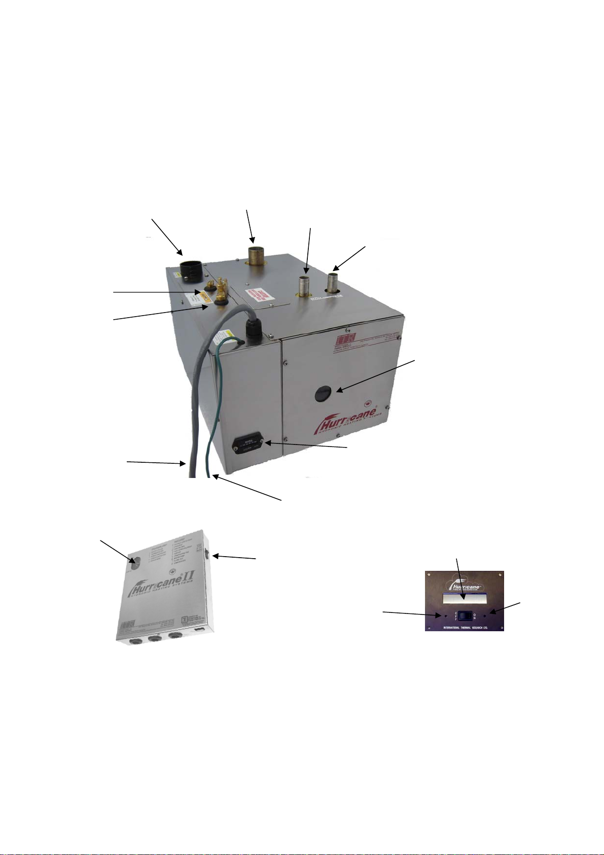
1.1. Component Views................................................................ 4
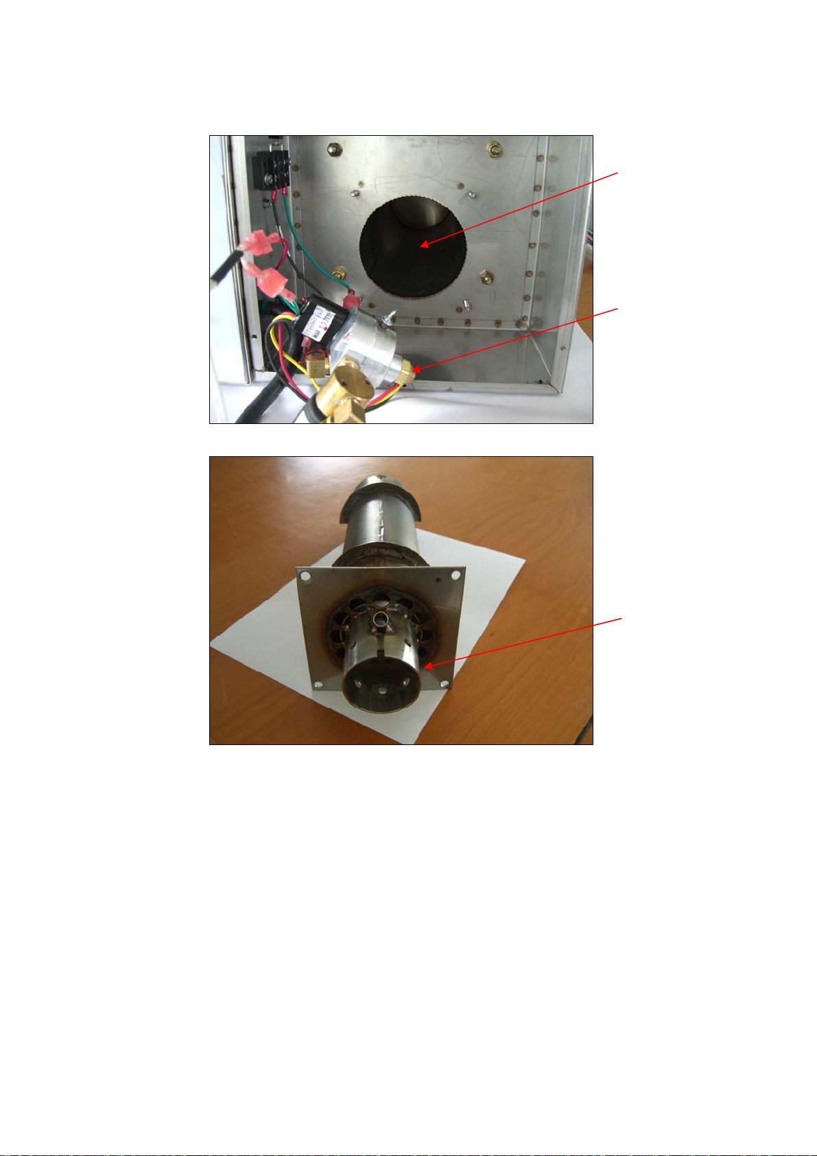
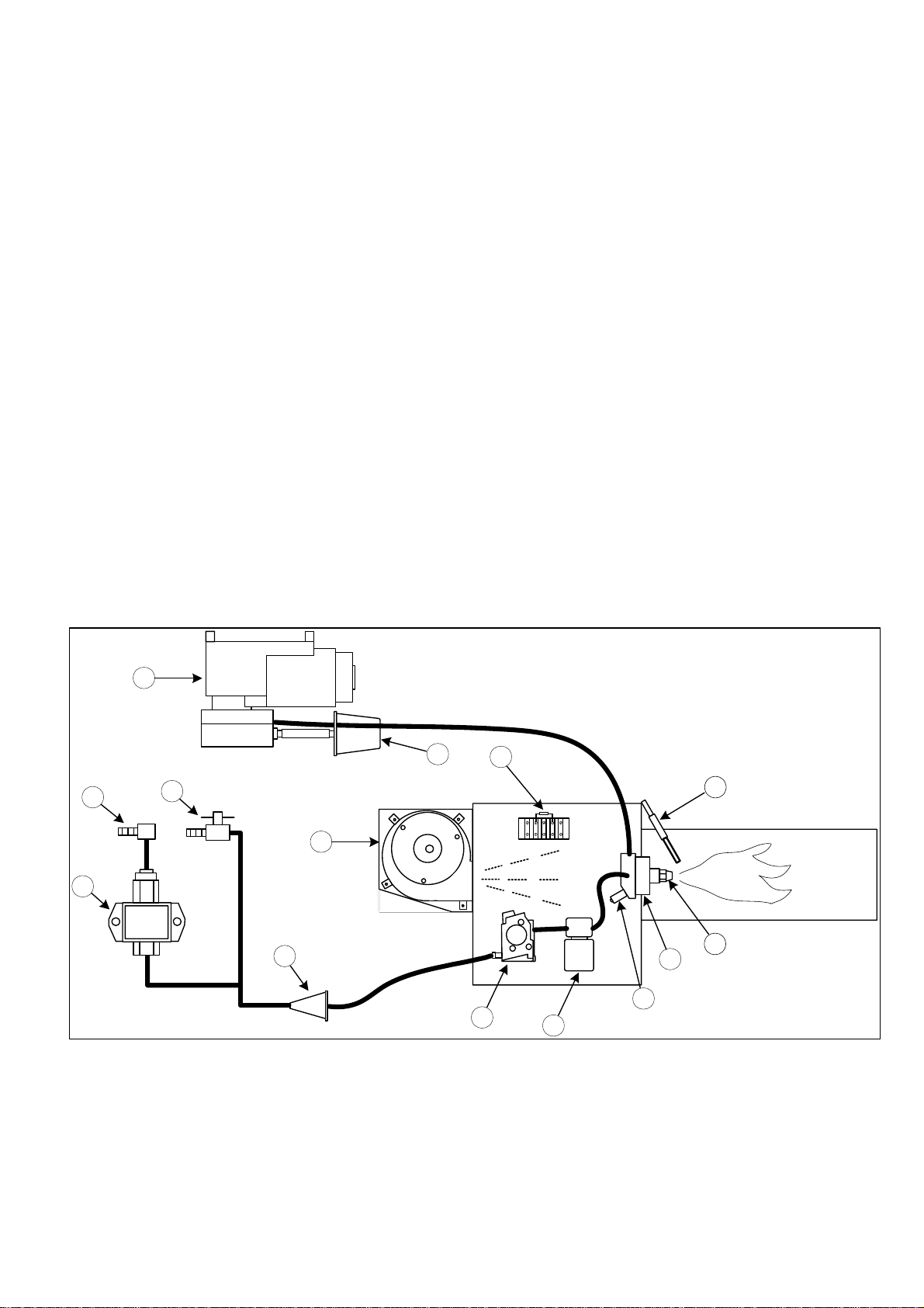
1.2. Burner............................................................................... 6
2. Control Board ........................................................................... 9
3. Troubleshooting .......................................................................13
3.1. Overview ..........................................................................13
3.2. Power On (Green) ..............................................................13
3.3. Burner On .........................................................................13
3.4. V- Service Switch Off .........................................................13
3.5. 9- Remote Switch Off.........................................................13
3.6. <- Heater Cycling (Normal Operation)...................................14
3.7. T- Thermostats Off (Normal Operation).................................14
3.8. 0- Voltage Low or High.......................................................15
3.9. 1- Overheat.......................................................................15
3.10. 2- Fuse Blown................................................................16
3.11. 3- Fuel Pump/Solenoid ....................................................16
3.12. 4- Ignitor ......................................................................16
3.13. 5- Combustion Fan..........................................................17
3.14. 6- Water Pump...............................................................17
3.15. 7- Flame Out..................................................................18
3.16. 8- Compressor ...............................................................19
3.17. )- Bypass Mode..............................................................19
3.18. Water Pump On (Green)...................................................20
3.19. Test Points .....................................................................20
3.20. LCD Readout Remote Panel ..............................................21
3.21. Flame Sensor Module.......................................................21
3.22. Reduced Output ..............................................................22
3.23. Smokey, Smelly Exhaust..................................................22
4. Step-by-step Troubleshooting ..............................................23
4.1. Flame Out.........................................................................23
4.2. Voltage.............................................................................29
5. Servicing the Hurricane SCH25.............................................31
5.1. Indications Service Is Required ............................................31
5.2. Cleaning the Combustion Chamber .......................................32
5.3. Parts Replacements............................................................33
5.3.1. Fuel Solenoid...............................................................33

5.3.2. Igniter........................................................................34
5.3.3. Fuel Nozzle..................................................................35
5.3.4. Flame Sensor...............................................................36
Appendices....................................................................................37
Appendix 1 - Technical Bulletins ....................................................37

Page 1
General Information
TOOLS
The tools in this list should be considered the minimum required for
performance of routine maintenance, servicing and minor repair work.
•Spanner sizes 11/32, 9/16, 5/8, 7/8, 15/16, 1 3/8
•Socket sizes ¼, 5/16, 7/16, 11/32
•Adjustable crescent spanner
•Phillips head screwdriver No. 2
•Flat head screwdriver
•Pliers – vice grip
•Pliers – needle nose
•Multimeter
MAXIMUM TORQUE VALUES
The fasteners used to assemble this heater are all US thread size. Most
threaded fasteners should be tightened to a specific torque value. Over
tightening the fastener can weaken it and cause it to break, while under
tightening can cause it to eventually come loose. Below is a table with
the specific torque values for each type of bolt/screw used in this heater.
Be sure to follow the recommendations closely.
Table 1: Fastener Torque values
U.S. Thread Size Ft-lbs In-lbs Nm
#8 2 24 3
#10 3 36 4.5
¼-20 6 to 9 72 to 108 9 to 12
3/8-16 22 to 32 264 to 384 30 to 43

Page 2

Page 3
1. Operation of the Hurricane SCH25
The Hurricane SCH25 has a single source of heat; a 25,000 BTU burner.
EXHAUST
HOT WATER
OUT
AIR INTAKE
COLD WATER
IN
FLAME
OBSERVATION
WINDOW
HOURMETER
FUEL INLET
FUEL RETURN
CABLE TO
CONTROL BOX
NEGATIVE TO
BATTERY
SERVICE
SWITCH
DIAGNOSTIC
CODE
WINDOW
CONTROL BOX REMOTE SWITCH
LCD DISPLAY
WARNING
BUZZER
RESET
BUTTON

Page 4
1.1. Component Views
COMPRESSO
R
FUEL PUMP
COMBUSTION FAN
FUEL REGULATO
R
HOURMETE
R
THERMAL CUTOFF
IGNITE
R
FUEL BLOCK
FLAME SENSO
R
HOURMETE
R
FUEL SOLENOID
BURNER &
COUNTERFLOW
TUBE
FUEL
BLEED/RETURN
VALVE

Page 5
BURNER &
COUNTERFLOW
TUBE
COMBUSTION
CHAMBER
NOZZLE

Page 6
1.2. Burner
The burner consists of the following components:
1. Fuel inlet
2. Fuel Pump
3. Fuel return/bleed
4. Fuel filter
5. Fuel regulator
6. Fuel solenoid
7. Flame sensor
8. Nozzle block
9. Nozzle
10. Igniter
11. Combustion fan
12. Thermal cutoff
13. Compressor
14. Air filter
When the heater is turned on (service switch on and remote switch on)
and there is a call for heat from either the room thermostat and/or the
cylinder thermostat, it will go through the following ignition sequence:
1
2
3
4
56
89
11
13
14
7
10
12
Figure 1: Burner schematic

Page 7
1. The combustion fan will turn ON and run for 20 seconds.
2. The igniter will turn ON and the combustion fan will turn OFF.
3. The igniter will glow for 10 seconds to allow it to reach ignition
temperature.
4. After the igniter has been glowing for 10 seconds, the air compressor,
fuel pump, fuel solenoid and combustion fan will turn ON.
5. The air compressor provides a constant air supply to the nozzle under
a specific pressure and flow rate. The air is filtered before it enters
the compressor. In the nozzle the compressed air is guided over the
tip of the nozzle where it creates a negative pressure in the centre
tube. This negative pressure is used to draw fuel from the fuel
regulator. All fuel lines from the regulator to the nozzle must be
airtight. Any leaks will have an adverse effect on the flame. The
nozzle produces a solid cone spray pattern with extremely fine
particles of fuel. This spray is then ignited when it makes contact
with the igniter.
6. The fuel pump pumps fuel from the fuel tank up to the fuel regulator.
Before the fuel enters the fuel pump, it should pass through an
external filter. There is also an internal filter between the fuel pump
and the fuel regulator. Fuel is only allowed to pass the regulator
when there is a negative pressure between the regulator and the
nozzle. In between the fuel regulator and the nozzle is a fuel
solenoid. This fuel solenoid prevents the fuel being drawn back from
the nozzle when the burner is off. This allows for a clean ignition.
7. The combustion fan draws outside air. This is used to create a forced
air flow through the combustion chamber. This is for optimal
combustion and to exhaust the combustion gases through an exhaust
pipe system into the atmosphere.
8. After ignition takes place, the igniter will remain ON for an additional
5 seconds. This is so if there are any air bubbles in the fuel system,
the atomised fuel will continue to be ignited.
9. After 5 seconds, the igniter will turn OFF and the air compressor, fuel
pump, fuel solenoid and combustion fan will remain ON. At this point
the flame sensor will also look for a flame.
10.The burner will continue to run until one of the following occurs:
1. The coolant inside the heater reaches the set operating
temperature range
2. The heater is switched off
3. One of the components faults
4. A flame out occurs
5. A voltage fault occurs
Note: After any of the above situations, the combustion fan will run for
2 minutes to purge exhaust gases from the system. The only time the
combustion fan will not run after the system cycles or faults is when the

Page 8
combustion fan has faulted. In this case all of the burner components
will shut down immediately.

Page 9
2. Control Board
•Control box and board – The main control board is contained in a
stainless steel control box and is connected to the heater via a
15ft/4.6m long, ½in/13mm diameter interface cable.
All components in the heater unit are pre-wired to the main
terminal block on the control board - Figure 3 shows the
connections.
•Fuses – The control board contains four fuse holders with fuses pre-
installed. These are standard, automotive, spade type fuses available
from most auto parts stores. The fuses are (from left to right):
Fan/Logic – 10 amps
Main – 15 amps
Pump – 10 amps
Zone Fans – 10 amps
•Accessory terminal block – The following components need to be
wired into the accessory terminal block on the control board:
Thermostats (up to four). Additional 4 zone board available for
larger applications.
Fan heaters / Solenoid Valves / Motorised Valves
Fan speed switches (if any)
•Fault bypass and reset buttons – These buttons allow testing of
the heating system by bypassing the fault-sensing circuit. This fault
bypass feature is engaged by depressing and holding the top button,
depressing and releasing the bottom button, and then releasing the
top button. To reset the heater, turn the heater service switch OFF,
then ON again.
Do not leave heater running unattended in bypass mode. Bypass
mode runs for five (5) minutes.
•Test points – These points on the control board allow
troubleshooting of the heating system. For detailed information on
the use of each test point, see 3.19.
•Diagnostic display – This is an LED indicator for the diagnostics of
the heater. It also has signal lights for the heater power and
circulating pump.
•Circulating pump jumper – This jumper on the control board allows
you to run the circulating pump and test the system circulation
without turning the heater on.

Page 10
•Battery connector – Connection points for the positive and negative
power from the house battery to the heater.
•Remote connector – Connection point for the cable from the remote
LCD panel.
•Service switch – The service switch allows full (service switch on) or
partial (service switch off) operation of the functions of the heater
control board. In the OFF position, it will only allow the circulating
pump and cabin fan circuitry of the control board to run in response
to both a thermostat calling for heat and an external heat source
(engine) supplying adequate heat to the system. The operating
circuitry of the burner in the heater itself is non-functional. In the ON
position, all operations and features of the heater and control board
are functional. In normal operation, the service switch is left ON.
NOTE: The service switch has an additional short circuit fault (# 3 –
4 – 5 – 6 – 8) reset function. This is performed by turning the
service switch OFF, then ON.

Page 11
8
10
15
10
-+
SERVICE
PUMP
FAN
T1 T2 T3 T4 T5 T6 T7
T8 T9 T10 T11 T12 T13 T14
SENS-
SENS+
S_OUT
A/S
HI
TEMP
FUEL
FAN
COMP
IGN
BURNER
JS2
BYPASS
RESET
TC F1 T1 W1 W2 A1 S/W P+ T2 F2 T3 F3 T4 F4
PUMP
10
PUMP JUMPER IN "OFF" POSITION
Figure 2: Control Board

Page 12
Figure 3: Wiring Diagram

Page 13
3. Troubleshooting
3.1. Overview
The electronic board consists of a flash micro controller programmed to
monitor the timing and safety function of the heater. Each time the
board is energized by a call for heat, it will check its own circuits for any
problems. Should a problem exist, the board will shut down.
You can easily monitor your HURRICANE®SCH25 heater’s operation by
checking the electronic control box. Any fault or problem will be
immediately picked up by the control board and an LED diagnostic code
indicator will light up to pinpoint the fault. Once the fault has been
corrected, it can be reset by switching the service or remote switch OFF,
then ON again. The diagnostic codes are described below.
3.2. Power On (Green)
The POWER ON indicator is lit whenever the service switch on the control
box is ON and if the remote panel is switched ON, a small red LED near
the lower right hand side of the digit on the remote panel will also glow.
If this light does not come on, check to see if the service switch is ON.
If the power on light does NOT come on:
•Check for a blown fuse.
3.3. Burner On
No diagnostic code will be displayed on the main board or the remote
panel when the burner is ON and operating normally. A small red LED
will glow near the lower right hand side of the digital on the remote
panel indicating it is ON.
3.4. V- Service Switch Off
The service switch is switched OFF.
•The burner will shut down if it has been running.
•The diagnostic code, Vwill be displayed.
•The control board will purge the system with the combustion fan and
circulating pump for two minutes. At the end of the purge period, the
system will power down and will go into a low power consumption
mode (10mA max.). There will not be any display or LEDs lit.
3.5. 9- Remote Switch Off
The remote panel is switched OFF.
•The burner will shut down.

Page 14
•The diagnostic 9code will be displayed.
•The control board will purge the system with the combustion fan and
circulating pump for two minutes.
•If the remote switch is put in the ON position, the control board will
resume operation and a small red LED will glow near the lower right
hand corner of the digit. If there is no diagnostic code displayed or
small LED glowing:
Make sure the service switch is ON.
Make sure the remote switch cable is plugged into the control
box and remote switch.
Make sure the remote rocker switch is working.
Check the cable continuity.
3.6. <- Heater Cycling (Normal Operation)
The operating aquastat installed on the water jacket has been satisfied.
•The burner will shut down.
•The diagnostic code, <will be displayed.
•The control board will purge the burner with the combustion fan for
two minutes and then stop. The circulating pump will run until the
last thermostat is satisfied, then purge for two minutes and stop.
•To maintain the system temperature the operating aquastat will cycle
the burner off at 170°F (77°C) and on again at 140°F (60°C).
•If the heater cools and fails to resume operations and the diagnostic
code <continues to be displayed, the aquastat is faulty or has an
open connection.
3.7. T- Thermostats Off (Normal Operation)
All thermostats and aquastats are satisfied.
•The burner will shut down.
•The diagnostic code, Twill be displayed.
•The control board will purge the system with the combustion fan and
circulating pump for two minutes. When any thermostat or aquastat
calls for heat, the heater will resume normal operation.

Page 15
•If the heater fails to resume operations, check the thermostat and
their connections.
3.8. 0- Voltage Low or High
The battery or power supply voltage is below 11Vdc or above 15Vdc
•The burner will shut down.
•The diagnostic code, 0will be displayed.
•The buzzer will sound for 10 seconds.
•The control board will purge the system with the combustion fan and
circulating pump for two minutes while it is checking if the voltage
fault is still present.
If the voltage fault has cleared, the control board will reset the alarm
and restart the burner. If the condition has not cleared by the end of
the purge period, the diagnostic code 0 will remain displayed. The
control board will continue to check the voltage every half hour until the
voltage fault has cleared and then restart the burner. To manually reset
the fault, switch the service switch or the remote panel switch OFF then
ON again.
3.9. 1- Overheat
The high temperature limit has been reached.
•The burner will shut down.
•The diagnostic code, 1will be displayed.
•The buzzer will sound for 10 seconds.
•The control board will purge the system with the combustion fan and
circulating pump for two minutes while it is checking if the overheat
condition exists. If the condition exists, the diagnostic code 1will
continue to be displayed.
•In order to restart the burner, first check the circulating pump, the
level of the coolant, and the movement of the coolant while the
circulating pump is running. Reset the high limit aquastat (inside
heater) and the fault (switch service or remote switch OFF then ON
again). If the fault does not reset, check for a faulty aquastat and
proper ground. If equipped with AC elements, reset the AC hi-limit
aquastat also.
•If a number Idiagnostic code lights up and the heater is not in an
overheat condition, check the ground from the heater ground wire to

Page 16
the battery. The ground wire should be a minimum 10 gauge and
connected directly to the battery.
3.10. 2- Fuse Blown
One of the fuses on the control board has blown.
•The burner will shut down.
•The diagnostic code, 2will be displayed.
•The buzzer will sound for 10 seconds.
•The control board will purge the system with the combustion fan and
circulating pump for two minutes while it is checking for a blown fuse.
•If a blown fuse exists, the diagnostic code 2will continue to be
displayed.
•In order to restart the burner, replace any blown fuses with one of
the proper size. Then reset the fault by switching the service switch
or the remote panel switch OFF then ON again.
3.11. 3- Fuel Pump/Solenoid
The fuel pump or fuel solenoid has shorted.
•The burner will shut down.
•The diagnostic code, 3will be displayed.
•The buzzer will sound for 10 seconds.
•The control board will purge the system with the combustion fan and
circulating pump for two minutes.
•In order to restart the burner, check the fuel pump and solenoid for a
short circuit. Then reset the fault by switching the service switch OFF
then ON again.
The remote panel switch does not reset short circuit faults.
3.12. 4- Ignitor
The ignitor is open or shorted
•The burner will shut down.
•The diagnostic code, 4will be displayed.
Table of contents
Popular Industrial Equipment manuals by other brands

Grundfos
Grundfos Polydos 412E instructions

ABB
ABB TPL67-C32 Operation manual

R.V.R. Elettronica
R.V.R. Elettronica PJ5KPS User's & technical manual

MyBinding
MyBinding Formax FD 4040 instruction manual

Siemens
Siemens 3VA9131-0WF 0 Series operating instructions

Siemens
Siemens SIWAREX WL280 operating instructions