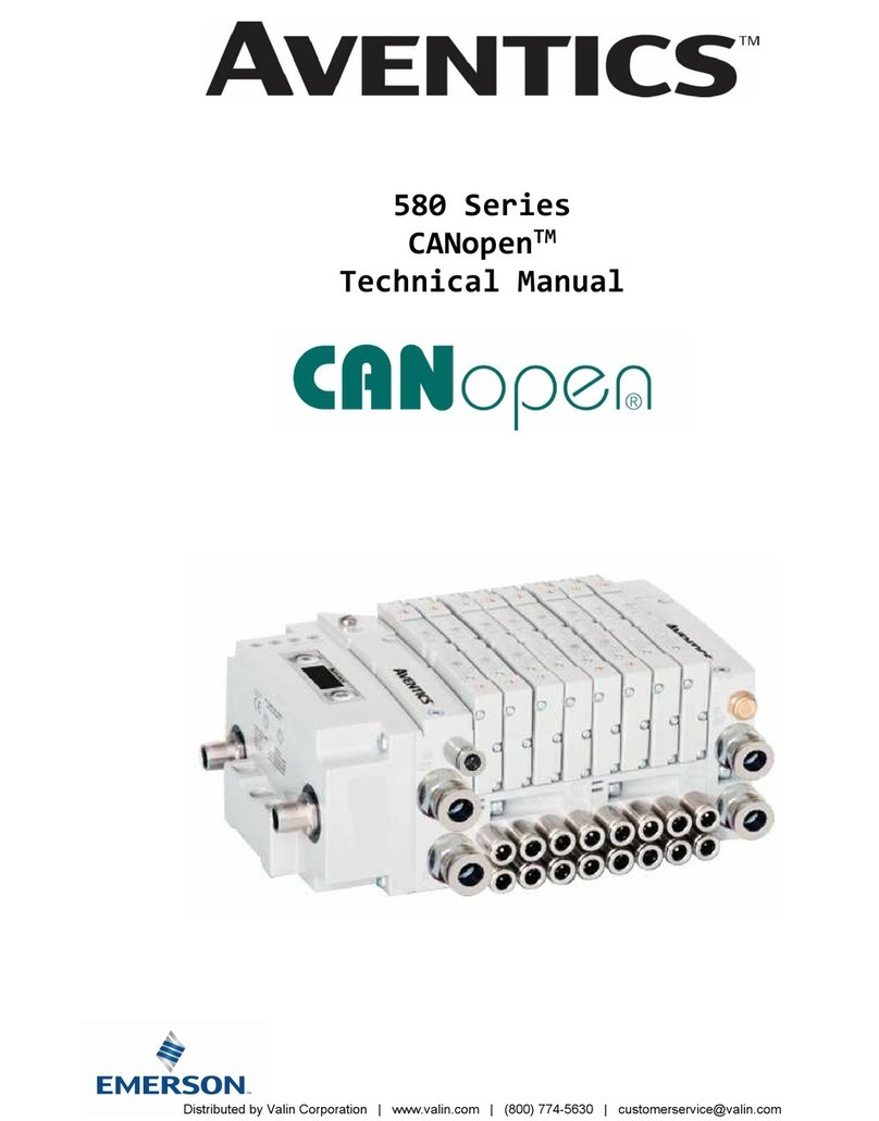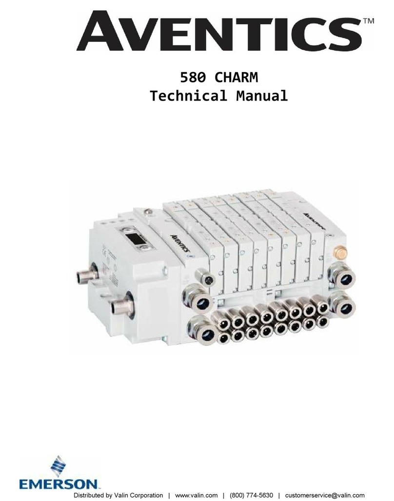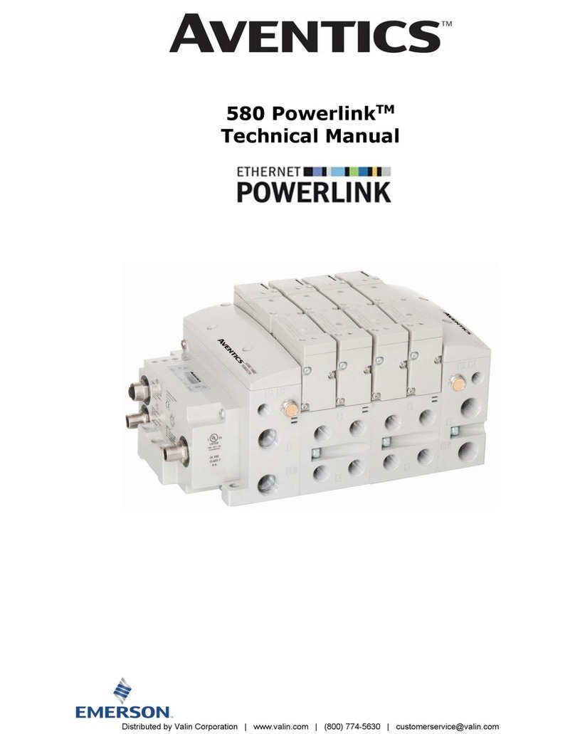
580 PROFINETTM Technical Manual
1-4
TD580PNTM1-5EN 8/23
Subject to change without notice
http://www.Emerson.com
Table of Contents
PAGE
1. About PROFINETTM ................................................................................................................................................ 5
1.1 Overview ................................................................................................................................................ 5
1.2 580 PROFINETTM Node Features ................................................................................................................. 5
2. 580 PROFINETTM Introduction ................................................................................................................................. 6
2.1 Pneumatic Valve Manifold –501 Series shown............................................................................................. 7
2.2 500 Series Manifold Stations ..................................................................................................................... 8
2.3 Z-Board™Connectors .............................................................................................................................. 9
3. Zoned Power...................................................................................................................................................... 10
3.1 Zoned Power Safety and 580 Electronics alternatives ................................................................................. 10
3.2 503 Series Zoned Power application ......................................................................................................... 11
3.3 503 Series Zoned Power example ............................................................................................................ 12
4. Communication Module ....................................................................................................................................... 13
4.1 580 PROFINETTM Node ............................................................................................................................ 13
4.2 580 Node Description ............................................................................................................................. 14
4.3 Connector Pin-Outs ................................................................................................................................ 15
4.4 Electrical Connections............................................................................................................................. 16
4.5 Chassis Ground ..................................................................................................................................... 17
4.6 Power Consumption ............................................................................................................................... 18
4.7 Recommended External Fuses ................................................................................................................. 19
4.8 Diagnostics –580 PROFINETTM Node LED Functions.................................................................................... 20
5. Extended Coil Capability ...................................................................................................................................... 21
5.1 500 Series Extended Coil Configurations ................................................................................................... 21
5.2 500 Series Extended IO Mapping ............................................................................................................. 24
5.3 501 Series, up to 64 solenoid coils ........................................................................................................... 25
5.4 501 Series, up to 128 solenoid coils ......................................................................................................... 26
5.5 502 and 503 Series, up to 80 coils ........................................................................................................... 27
6. Profinet Node Graphic Display .............................................................................................................................. 28
6.1 Station Name ........................................................................................................................................ 29
6.2 IP Address Sub Menu ............................................................................................................................. 29
6.3 Subnet Mask Sub-Menu .......................................................................................................................... 30
6.4 Gateway IP ........................................................................................................................................... 31
6.5 Config. Mode......................................................................................................................................... 32
6.6 Web Server Sub-Menu............................................................................................................................ 33
6.7 MAC Address Sub-Menu.......................................................................................................................... 34
6.8 Model Number Sub-Menu........................................................................................................................ 34
6.9 Advanced Settings –Flip Display ............................................................................................................. 35
6.10 Advanced Settings –Parameters ............................................................................................................. 36
6.11 Factory Defaults Factory Defaults............................................................................................................. 37
6.12 Diagnostics ........................................................................................................................................... 38
6.14 Diagnostics Self-Test.............................................................................................................................. 38
6.14 Error Messages..................................................................................................................................... 40
7. PROFINETTM Integrated Web Server ...................................................................................................................... 41
7.1 Connecting to an Aventics 580 ProfinetTM Node .......................................................................................... 41
7.2 Using the Functionality of the 580 ProfinetTM Web Server ............................................................................ 42
7.3 Station Name and IP Address Configuration .............................................................................................. 48
7.4 User Configurable Device Parameters ....................................................................................................... 49
7.5 Communication Fault/Idle Mode Parameter ............................................................................................... 50
8. 580 ProfinetTM Commissioning .............................................................................................................................. 50
8.1 GSDML File ........................................................................................................................................... 51
8.2 580 ProfinetTM PLC Configuration.............................................................................................................. 51
8.3 580 ProfinetTM Station Name ................................................................................................................... 55
9. PROFINETTM Mapping........................................................................................................................................... 56
9.1 I/O Sizes .............................................................................................................................................. 56
9.2 Bit Mapping Rules .................................................................................................................................. 56
9.3 Mapping Example No. 1 .......................................................................................................................... 57
9.4 Mapping Example No. 2 .......................................................................................................................... 58
10. Appendix ......................................................................................................................................................... 59
10.1 System Specifications............................................................................................................................. 59
10.2 Factory Default Settings ......................................................................................................................... 59
10.3 Troubleshooting..................................................................................................................................... 60
10.4 Glossary of Terms.................................................................................................................................. 60
Distributed
by
Valin
Corporation
|
www.valin.com
|
(800)
774-5630
|
[email protected]