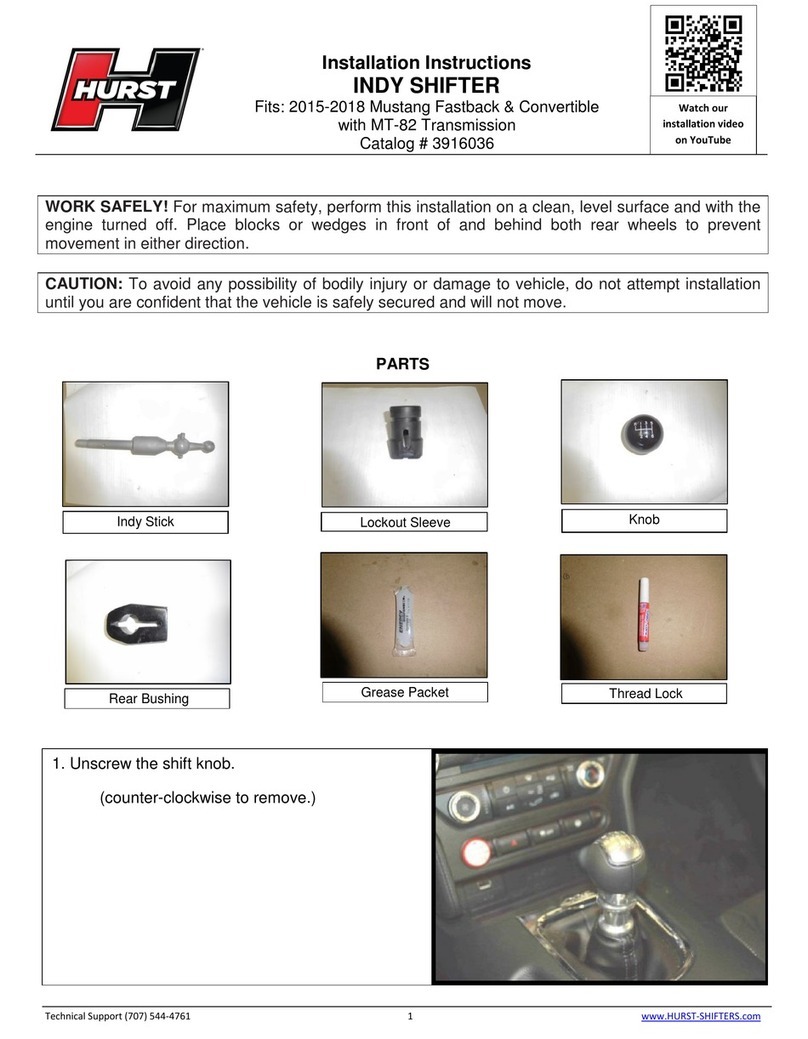
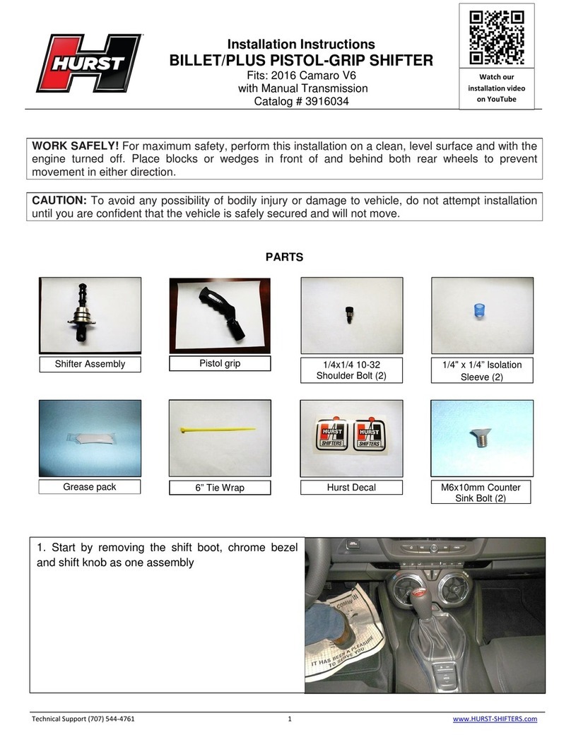
HURST 3910201 User manual

WORK SAFELY! For maximum safety, perform this installation on a clean, level surface and with the
engine turned off. Place blocks or wedges in front of and behind both rear wheels to prevent
movement in either direction.
CAUTION: To avoid any possibility of bodily injury or damage to vehicle, do not attempt installation
until you are confident that the vehicle is safely secured and will not move.
NOTE: FOR PHOTOGRAPHIC PURPOSES, A 2010 MUSTANG IS SHOWN THROUGHOUT
THESE INSTRUCTIONS. 2005-2009 GT KITS INSTALL WITH IDENTICAL STEPS.
PARTS
TechnicalSupport(707)544‐4761 1 www.HURST‐SHIFTERS.com
Installation Instructions
HURST COMPETITION AND BILLET/PLUS SHIFTER
2005-2010 Mustang w/5-speed Manual Transmission (GT only)
Catalog# 3910201
Knob Hurst Stick Shifter (3915201 shown)
Knob Nut
Stick Mounting
Screws (2) Stick Mounting
Washers
(
2
)
Neoprene
Isolators (2) Boot Support and Zip Tie

TOOLS
TechnicalSupport(707)544‐4761 2 www.HURST‐SHIFTERS.com
Flat Blade
Screwdriver Plastic Trim
Tool Extension 7/32” Hex
Wrench Ratchet
10mm,13mm,
9/16”Wrench 10mm Deep
Socket Cutting Pliers Floor Jack Jack Stands
STEP 1. Move the shift knob to the Neutral
position. (Set the parking brake to ensure that the
vehicle does not move during installation).
2005-2009: Work the upper part of the shift boot
out of the retainer groove of the shift knob and
slide down onto stick.
2005-2010: Remove the knob by turning counter
clockwise.
STEP 2. Remove the shifter boot.
2005-2009: Place fingers or Trim Tool underneath
outer corners of the shifter boot and pull up to
unsnap from the center console. Slide boot up and
over the shift stick and place the boot aside. Skip
to STEP 5.
TOOL:Plastic Trim Tool
2010: See STEP 3.

TechnicalSupport(707)544‐4761 3 www.HURST‐SHIFTERS.com
STEP 3. 2010 MUSTANGS ONLY:
Open the rear storage compartment cover on the
center console. Firmly grab the upper center
console and pull upward to unsnap from the lower
center console. (Opening the cup holder cover
may facilitate removal of the top center console
piece).
STEP 4. 2010 MUSTANGS ONLY:
Disconnect the ESC/Hazard/Trunk Release
harness from the bottom of the center console.
Remove the center console and set aside.
STEP 5. Remove rubber dust boot from shift stick
by pulling up and out of the floor pan opening and
sliding it over the shift stick. Set boot aside.
STEP 6. Carefully raise vehicle for under car
access.
TOOL: Floor Jack and Jack Stands

TechnicalSupport(707)544‐4761 4 www.HURST‐SHIFTERS.com
STEP 7. Remove the hex nut that secures the
transmission linkage rod to the bottom of the
shifter and set aside.
TOOL: 13mm Wrench
STEP 8. Remove the transmission linkage rod by
pulling it out of the stock shifter.
STEP 9. Remove the front bolt that attaches the
shifter assembly arm to the transmission and set
aside.
TOOL: 10mm Wrench
STEP 10. Remove the two (2) hex nuts that
secure the rear mount of the shifter assembly to
the floor and set aside.
TOOL: 10mm Deep Socket, Ratchet, Extension

Assembly
TechnicalSupport(707)544‐4761 5 www.HURST‐SHIFTERS.com
STEP 11. Remove the metal bracket from the rear
rubber mount and set aside.
NOTE: Some Mustangs may contain a clip on one
or both of the studs making the bracket difficult to
remove. Carefully remove the bracket by working
it from side to side until it is removed. DO NOT
force the bracket off the studs by pulling it down
as these clips can damage the threads.
(The picture shows a bracket with only one (1) clip
that has been moved out of the way instead of
being removed.)
STEP 12. Remove the stock shifter from the
vehicle. One method is to move the entire shifter
assembly down so that just the top part of the stick
is inside the vehicle. Then move the shifter
assembly forward enough so that the tail end of
the shifter can be pushed upwards through the
tunnel opening. Once the tail end is through the
opening, the shifter can be removed from the
inside of the vehicle.
STEP 13. Place the factory shifter on a workbench
and remove the two (2) metal flanged sleeves
from the front rubber bushings on the shifter
assembly arm.
TOOL: Flat Head Screwdriver

TechnicalSupport(707)544‐4761 6 www.HURST‐SHIFTERS.com
STEP 14. Remove the two (2) plastic bushings
from the bottom of the shifter. These bushings
should be removed by hand to not damage them.
STEP 15. Place the HURST shifter on a
workbench and insert the two (2) metal flanged
sleeves into the bushings in the HURST shifter
assembly arm.
STEP 16. Insert the two (2) plastic bushings into
the bottom of the HURST shifter.
STEP 17. From the inside of the vehicle, carefully
insert the HURST shifter assembly through the
console and into the opening in the floor tunnel. If
you can push the tail end of the shifter assembly
down into the tunnel from the inside, you should
do so. If not, this can be done from underneath the
vehicle.
NOTE: The ridges on the upper stick must face
towards the passen
g
er’s side.

TechnicalSupport(707)544‐4761 7 www.HURST‐SHIFTERS.com
STEP 18. From underneath the vehicle, work the
HURST shifter assembly forward so that the tail
end can go through the tunnel opening. (Follow
guidelines given in STEP 12). Then attach the
front shifter arm to the transmission and insert the
hex bolt removed in STEP 9 but do not tighten at
this time.
TOOL: 10mm Wrench
STEP 19. Attach the metal bracket to the rear
urethane mount on the HURST shifter assembly
and align the holes in the bracket with the two (2)
threaded studs on the vehicle. Replace the two
(2) hex nuts removed in STEP 10 and tighten
securely.
TOOL: 10mm Deep Socket, Ratchet, Extension
NOTE: Make sure the metal bracket “hugs” the
urethane mount and sits in its groove. The
urethane mount may need to be moved forward
or back to align with the bracket and the studs.
DO NOT over tighten the hex nuts. Excessive
force can break the studs.
STEP 20. Tighten the hex bolt from STEP 18 that
secures the shifter arm to the transmission. Insert
the transmission linkage rod into the bushings at
the bottom of the HURST shifter. Replace the hex
nut removed in STEP 7 and tighten securely.
TOOL: 10mm Wrench, 13mm Wrench
NOTE: Offset (long side) of connector located on
stick bottom must face towards the driver’s side. If
the serrations on the lower stick are facing the
passenger side, then the connector is in the
correct orientation.

TechnicalSupport(707)544‐4761 8 www.HURST‐SHIFTERS.com
STEP 21. Carefully lower vehicle. From inside
the vehicle, attach the HURST upper stick to the
lower stick with two (2) stick mounting washers
and two (2) stick mounting screws and tighten.
TOOL: 7/32 Hex Wrench (Allen Key)
STEP 22. OPTIONAL: ISOLATOR INSTALLATION
The provided neoprene isolators can be installed to
help reduce some of the transmission noise that
may be transmitted through the shifter stick. Install
one or both of the isolators between the lower stick
and the upper stick. Attach using two (2) washers
and two (2) screws and tighten.
NOTE: The isolators may not eliminate ALL
transmission noise or vibration and may reduce
shift feel and overall strength of the system.
STEP 23. Reinstall the rubber boot that was
removed in STEP 5. Push down the lower lip of the
boot through the vehicle’s tunnel to ensure a
proper seal. With the boot in place, test the shifter
operation. Move shifter through all the gears and
make sure that it engages each gear fully and that
the stick moves freely from side to side in the
Neutral position. The knob may be temporary
installed to aid in testing.

TechnicalSupport(707)544‐4761 9 www.HURST‐SHIFTERS.com
STEP 24. Push the rubber boot support onto the
HURST chrome stick.
STEP 25. Replace the shifter boot that was
removed in STEP 2.
2005-2009: Slide the boot over the HURST
chrome stick. Position the boot correctly and
carefully press down around the outer edges until
the retainer clips snap firmly into place. Work the
boot into the groove of the rubber boot support.
Skip to STEP 31.
2010: See STEP 26
STEP 26. 2010 MUSTANGS ONLY:
Remove the boot material from the plastic
retainer.
NOTE: The boot material is attached to the
plastic retainer with a strong adhesive. Slowly pull
on the boot to remove from retainer. Slight
tearing of the boot may occur. Alternatively, you
can use scissors or a blade to cut the boot free
from the retainer.
TOOL: (Optional) Scissors or a blade.

TechnicalSupport(707)544‐4761 10 www.HURST‐SHIFTERS.com
STEP 27. 2010 MUSTANGS ONLY:
Place the upper center console loosely over the
lower center console. Arrange the upper center
console in a way that will give you some working
room between both consoles. Slide the boot over
the HURST chrome stick.
STEP 28. 2010 MUSTANGS ONLY:
Work the boot over the rubber boot support.
Make sure the boot material is properly
orientated and attach a zip tie around the boot
material. Make sure the zip tie is in the groove of
the rubber boot support and tighten. Cut off the
excess zip tie material.
TOOL: Cutting pliers
STEP 29. 2010 MUSTANGS ONLY:
Reconnect the ESC/Hazard/Trunk Release
harness that was disconnected in STEP 4.
STEP 30. 2010 MUSTANGS ONLY:
Replace upper center console to lower center
console by snapping into place.

TechnicalSupport(707)544‐4761 11 www.HURST‐SHIFTERS.com
STEP 31. Attach the Knob Nut onto the HURST
stick and thread down as far as possible without
forcing it.
STEP 32. Screw on the HURST knob all the
way down until it contacts the knob nut, then
back it off until the orientation of the shift
pattern/logo is correct.
STEP 33. With one hand holding the knob in the
correct orientation, use the other hand to tighten
the knob nut up against the knob.
TOOL: 9/16” Wrench
STEP 34. Congratulations. You have now
installed HURST’s short throw shifter in your
Mustang.

IMPORTANT: RETAIN THESE INSTRUCTIONS FOR FUTURE REFERENCE
Technical Service
A highly trained technical service department is maintained by Hurst Performance to answer your
technical questions, provide additional product information and offer various recommendations.
Technical service calls, correspondence, and warranty questions should be directed to:
Hurst Performance Products
(707) 544-4761
www.Hurst-Shifters.com
TechnicalSupport(707)544‐4761 12 www.HURST‐SHIFTERS.com
This manual suits for next models
1
Other HURST Microphone System manuals
Popular Microphone System manuals by other brands

CleverMic
CleverMic BLS-4518C Operation instructions

SeeEyes
SeeEyes SC-IPC1201TW user manual

Motorola solutions
Motorola solutions WM800 user guide

Optelecom-nkf
Optelecom-nkf 9000 Series Installation and operation manual

Sony
Sony UWPV6/4244 operating instructions

Revolabs
Revolabs xTag 02-DSKSYS-D Installation and operation installation and operation guide