GENERAL INFORMATION
6
3
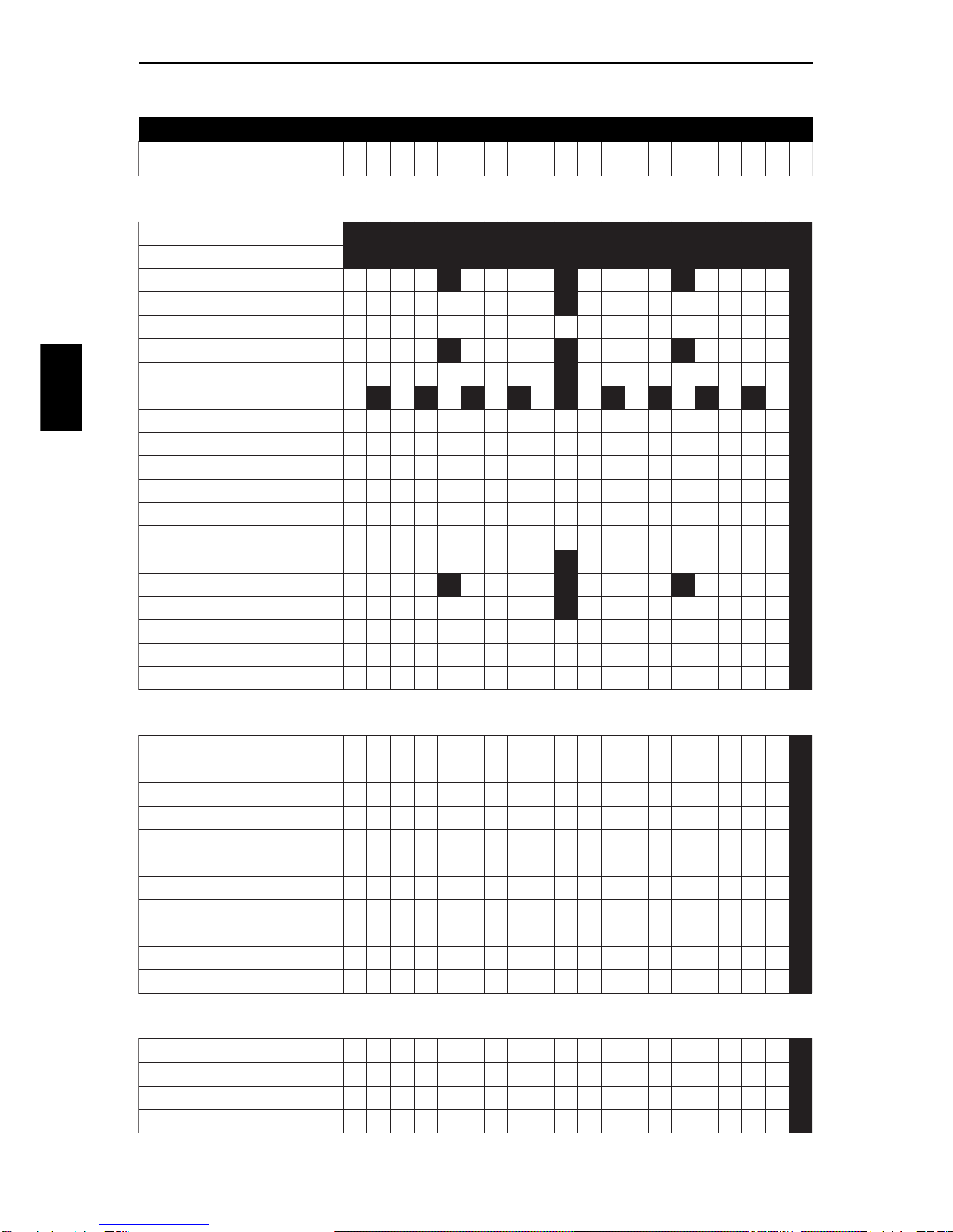
3SPECIFICATIONS
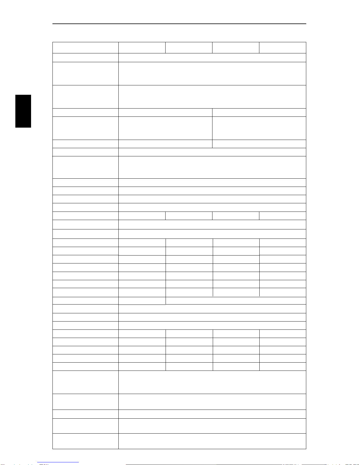
ENDURO MOTOCROSS ELDURO DESERT (FX)
Liquid cooled, 4-stroke single cylinder, SOHC-4 valves
400-models:399cc / Bore 92,0 mm x Stroke 60,1 mm
501-models:501cc / Bore 95,0 mm x Stroke 70,7 mm
600-models:595cc / Bore 95,0 mm x Stroke 84,0 mm
400-models:12,0:1
501-models:11,8:1
600-models:11,6:1
One automatic system activated by the
camshaft, oneactivatedbythekickstarter
and one operated by a manual lever
Fully automatic system activated by
the camshaft plus one operated by a
manual lever
Kick starter Electrical- and kick starter
2 mm ± 1 mm 2 mm ± 1 mm
Intake and Exhaust:0,10 mm
SUBJECT/MODEL
Engine type
Displacements
Compression ratio
Decompression system
Start system
Decomp.cable clearance
Valve clearance Orbit oilpump and reedvalve controlled lubrication
Oil-cooled piston and connecting rod
Replaceable micro filter and washable oil screen
1,0 Litre Synthetic SAE 5W-50 API SG/CF (minimum SAE 15W-50)
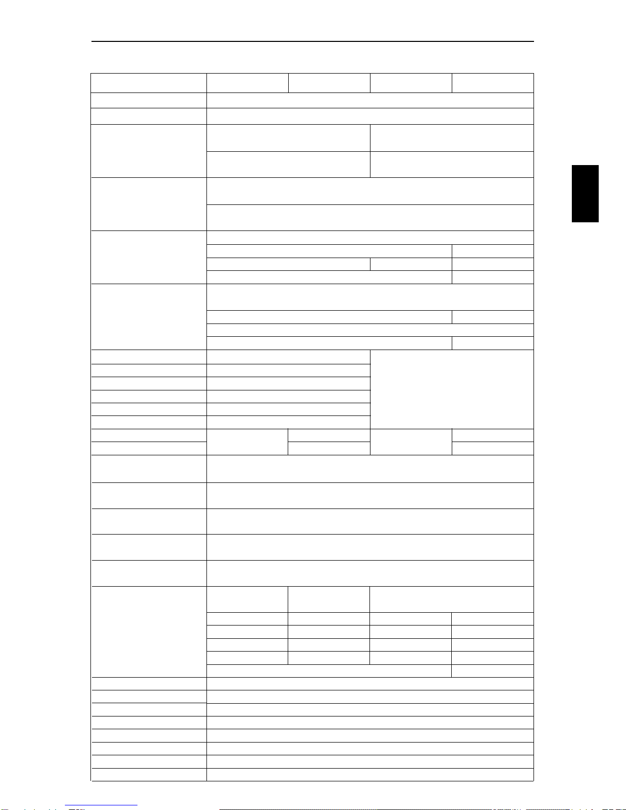
SEM, CDI, DFC™;Dynamic Force Control
Lubrication
Engine oil
Ignition NGK DCPR8E / 0,7 mmSpark plug / gap 1,3 litre of 50% Anti-freeze, with corrosion inhibitor, and 50% waterCoolant 12V / 70 + 70 W Not available 12 V / 70 + 70W 12 V / 70 + 70 WAlternator
Inox steel pipes, 2 into 1 collector, Aluminium/Inox silencer (FCTitanium/Inox)
US-versions except FC models equipped with spark arrester
Exhaust system
Fuel capacity All models except FR 600 E:9 litres
FR 600 E: 25 litres
520 O-ring chain
15/42 - 2,800
15/42 - 2,800
13/48 - 3,692 13/48 - 3,692 13/48 - 3,692
15/48 - 3,200 (15/48 - 3,200) 15/48 - 3,200 15/48 - 3,200
15/48 - 3,200 (15/42 - 2,800) 15/48 - 3,200 15/48 - 3,200
400-models:Dellorto PHM 38
501- & 600-models:Dellorto PHM 40
Dual Sport USA - FS 600:Edelbrock Qwiksilver 38
All models except FR 600 E:Single foam filter
FR 600 E:Double foam filters
RON 98 (octane), unleaded
29/78 - 2,690
Spur gears
Clutch hydraulic oil
Secondary transmission
Ratios 501/4-speed
600/4-speed
400/6-speed
501/6-speed
600/6-speed
Carburettor
(std. jetting see page 8)
Air filtration
Fuel
Ratio
Primary transmission
Hydraulic, 7 friction- and 8 mating plates in oil bathClutch
Gearbox
Ratios 1st gear
2nd gear
3rd gear
4th gear
5th gear
6th gear
Mineral oil SAE 2-7W
6-speedWR 4 or (6)-speed CR 6-speedWR 6-speed S-WR
15/32 - 2,133 13/34 - 2,615 15/32 - 2,133
*17/30 - 1,765 18/28 - 1,555 17/30 - 1,765 18/28 - 1,555
*20/27 - 1,350 20/25 - 1,250 20/27 - 1,350 20/25 - 1,250
*23/24 - 1,043 23/24 - 1,043 23/24 - 1,043 23/24 - 1,043
25/22 - 0,880 (24/22 - 0,917) 25/22 - 0,880 25/22 - 0,880
*FC 4-speed WR
*13/34 - 2,615
(25/21 - 0,840) 27/20 - 0,741 27/20 - 0,741
27/20 - 0,741


 Supplementary service manual")