GENERAL INFORMATION
6
3
3
SPECIFICATIONS
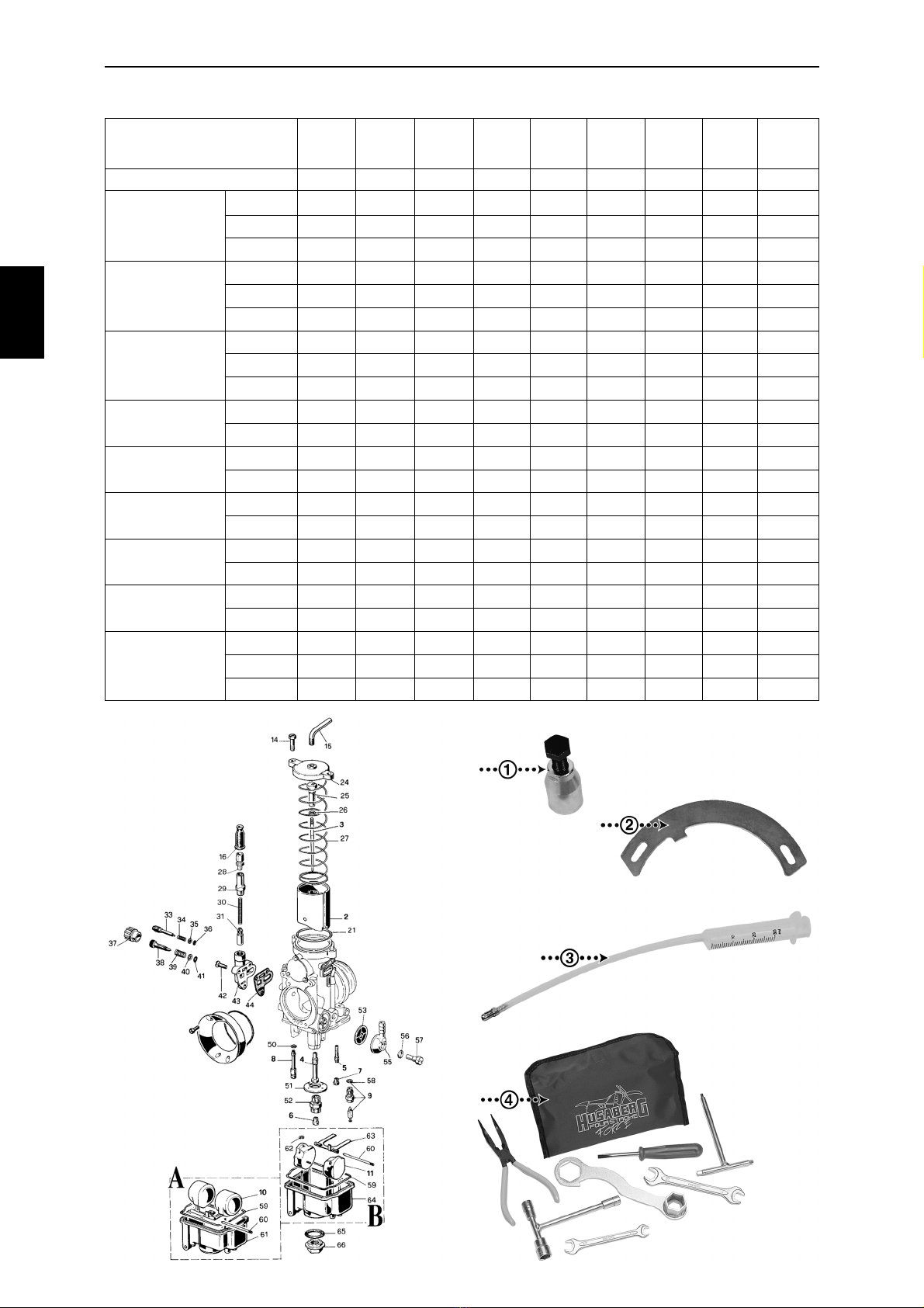
SUBJECT/MODEL FE 400 e FE 501 e FE 650 e FS 400 e FS 650 e FS 400 c FS 650 c FC 470/6 FC 550/4 FC 550/6 FC 470 e FX 470 e FX 650 e
Displacement 399cc 501cc 644cc 399cc 644cc 399cc 644cc 472cc 550cc 550cc 472cc 472cc 644cc
Bore x Stroke (mm) 92 x 60,1 95 x 70,7 100 x 82,0 92 x 60,1 100 x 82,0 92 x 60,1 100 x 82,0 100 x 60,1 100 x 70,0 100 x 70,7 100 x 60,1 100 x 60,1 100 x 82,0
Compression ratio 12,5:1 11,8:1 11,0:1 12,5:1 11,0:1 12,5:1 11,0:1 12,4:1 12,7:1 12,7:1 12,4.1 12,4:1 11,0:1
Start system Electrical and kick-starter Kick-starter Electrical and kick-starter
Decompression system Three separate ones; one activated by the kickstart lever, one activated by the camshaft and one activated by a lever on the handlebar
Decomp. cable clearance 2mm ± 1mm / 0,08 in ± 0,04 in.
Engine Liquid cooled single cylinder 4-stroke, SOHC-4 valves, counter balancer
Valve clearance Intake and Exhaust: 0,10mm / 0,004 in.
Lubrication system Orbit oil pump and reed valve controlled. High pressure jet spray of piston and connecting rod, pressure lubrication of connecting rod bearing and rocker arms. Oil screen and micro filter
Engine oil 1,0 Litre Synthetic SAE 5W-50 API SG/CF (minimum SAE 10W-50)
Ignition system SEM Dynamic Force Control, DFC™, Dual Ignition Curves; High & Low. A load sensitive digital system with six sensors
Spark plug - Spark plug gap NGK DCPR8E - 0,6 mm / 0,025 in.
Alternator 12 V 70 + 70 W Not available 12 V 70 + 70 W
Air intake system Single foam filter
Carburettor (DELLORTO) PHM 38 PHM 40 PHM 40 PHM 38 PHM 40 PHM 40 PHM 40 PHM 40 PHM 40 PHM 40 PHM 40 PHM 40 PHM 40
Fuel RON 98 (octane), unleaded
Exhaust system Chrome plated steel pipes, 2 into 1 collector, Aluminium/steel silencer. USA versions, except FC and FSc models, equipped with spark arresters
Coolant 1,3 Litre of 50% Anti-freeze, with corrosion inhibitor, and 50% water
Clutch Hydraulic, 7 friction- and 8 mating plates in oil bath
Clutch hydraulic oil Mineral oil SAE 2-7W
Wear limit clutch discs 19,6 mm / 0,772 in.
Primary transmission Spur gears, ratio 29/78 - 2,690
Gearbox 6-speed 6-speed 6-speed 6-speed 6-speed 6-speed 6-speed 6-speed CR 4-speed 6-speed CR 6-speed CR 6-speed 6-speed
Ratios 1st: 14/33 - 2,357 2nd: 17/30 - 1,765 3rd: 19/26 - 1,368 4th: 23/25 - 1,087 5th: 24/22 - 0,917 6th: 27/20 - 0,741 (6th CR: 25/21-0,840)
Secondary transmission D.I.D. 520 O-ring chain
Sprockets front/rear 13/48 15/48 15/42 15/42 15/42 15/42 15/42 13/42 15/42 15/48 13/48 13/48 15/42
Wear limit drive chain 272 mm - 18 chain reels (tensioned, center distance between reels)
Frame Heat treated BTR / 25CrMo4 steel
Caster 28,5°
Weight (dry) 109,8 kg 110,1 kg 110,9 kg 111,9 kg 113,1 kg 105,7 kg 106,8 kg 103,5 kg 103,5 kg 103,9 kg 109,6 kg 109,6 kg 110,4 kg
242 lb. 243 lb. 244 lb. 247 lb. 249 lb. 233 lb. 235 lb. 228 lb. 228 lb. 229 lb. 242 lb. 242 lb. 243 lb.


 Supplementary service manual")