Husqvarna FS 800 E User manual

HUSQVARNA CONSTRUCTION PRODUCTS
Operator’s manual
FS 800 E
FS 800 EM
Please read the Operator’s manual carefully and make sure
you understand the instructions before using the machine. English

2
Compliance with EU directives
Husqvarna Construction Products Sweden AB, Box 2098, SE-550 02 Jönköping, Sweden, tel: +46
(0)36-570 60 00, hereby certifies that its FS800 E/EM floor saw, having serial numbers 01001 onwards,
is manufactured in compliance with the Council's machinery directive 98/37/EG, low-voltage
directive 73/23/EEG and EMC directive 89/336/EEG, including amendments, and that the following
standards were used for guidance: EN 55 014-1, EN 55 014-2, EN 61 000-3-2, EN 50 144-1.
Jönköping 1 February 2001
Christer Carlberg
CEO

3
Contents ____________________________________________________________________________________________________________________________________________
General instructions. . . . . . . . . . . . . . . . . . . . . . . . . . . . . . . . . . . .4
Description and purpose. . . . . . . . . . . . . . . . . . . . . . . . . . . . . . . .4
Safety precautions. . . . . . . . . . . . . . . . . . . . . . . . . . . . . . . . . . . . .5
Rating plates, warning signs and their meanings. . . . . . . . . . .5
Preparations before starting. . . . . . . . . . . . . . . . . . . . . . . . . . . .5
Starting and operating. . . . . . . . . . . . . . . . . . . . . . . . . . . . . . . . .6
Maintenance. . . . . . . . . . . . . . . . . . . . . . . . . . . . . . . . . . . . . . . . . .7
Fitting and replacing diamond blades. . . . . . . . . . . . . . . . . . . . .8
Lifting and transport. . . . . . . . . . . . . . . . . . . . . . . . . . . . . . . . . . .9
Troubleshooting. . . . . . . . . . . . . . . . . . . . . . . . . . . . . . . . . . . . . . .9
Technical specifications. Noise and vibration measurement. 10
Parts list. . . . . . . . . . . . . . . . . . . . . . . . . . . . . . . . . .Appendix 1, 11
Exploded diagram. . . . . . . . . . . . . . . . . . . . . . . . .Appendix 2, 13

4
The FS800 E/EM floor saw is a professional machine designed
for cutting reinforced concrete, asphalt and stone.
This machine may only be used by those who have carefully
read this instruction manual and follow its instructions.
If you are unsure about any point please consult the supplier
before starting to use the machine.
You must not modify the saw in any way without obtaining
written approval from Husqvarna Construction Products
Sweden AB. Modifications that are not approved could lead
toseriousorfatalinjurytoyourselforothers.Husqvarna
Construction Products Sweden AB does not accept any liability
if the machine is used in any way or for any purpose that does
1. Description and purpose
The FS800 E/EM electric floor saw is designed for cutting re-
inforced concrete, asphalt and other stone material in the
building industry.
The saw has a full-width blade shaft, as shown in figure 1.1.2.
Thispermitsadiamondbladetobefittedoneithertherightof
left side of the machine to allow cutting into corners from
either side. The blade guard can be divided as shown in figure
1.1.5.
The floor saw is equipped with a water-cooling system, as
shown in figure 1.2.2 to ensure effective cooling of the
diamond blade and prevent dust formation.
The FS800 E/EM floor saw has the following controls:
•Height adjustment wheel as shown in figure 1.1.1.
• Blade shaft as shown in figure 1.1.2.
• Alignment guide for cutting a straight line as shown in
figure 1.1.4.
• Adjuster screw for the above, as shown in figure 1.1.3.
• Blade guard as shown in figure 1.1.5.
• Control panel with switch, phase inverter and emergency
stop as shown in figure 1.1.8.
• Power socket as shown in figure 1.2.1.
• Water-cooling nozzle as shown in figure 1.2.2.
• Guard for exposed drive shaft as shown in figure 1.2.3.
• Parking brake as shown in 1.2.4.
Figure 1.1
1.1.1. Height adjustment wheel
1.1.2. Pulley shaft
1.1.3. Adjuster screw for alignment guide
1.1.4. Alignment guide
1.1.5. Two-piece blade guard
1.1.6. Lifting handle for blade guard
1.1.7. Guide handle
1.1.8. Control panel with switch, phase inverter and emergency
stop
Figure 1.2
1.2.1. Power socket
1.2.2. Water-cooling coupling
1.2.3. Guard for exposed pulley shaft
1.2.4. Parking brake
General instructions ____________________________________________________________________________________________
1
8
6
3
4
2
1
3
4
5
7
2

5
2. Safety precautions
You must follow the safety precautions before starting the
machine. If the user does not follow these precautions then
neither Husqvarna Construction Products Sweden AB nor its re-
presentative can accept any liability, whether direct or indirect.
Themachinemustnotbeusedbyanyauthorisedpersonunless
supervised by an authorised and experienced operator.
WARNING! Make sure you have read and understood the
instructions in this manual before connecting the machine to
the electrical supply.
• Check that the electrical connections are secure and that
the power cable and plug comply with the specifications.
See section 9 Technical specifications.
• Make sure that no-one comes closer than 4 metres to the
front or side of the floor saw during operation.
• Check that the blade guard and blade flange guard are
fitted correctly.
• Theemergencystopmustnotbe deactivated duringstart-
up or operation.
• Before you start cutting, plan your work and clearly mark
out the area you intend to cut so that you can carry out
thework without riskofinjury or damagetothe machine.
See figure 3,1.
• Check the building drawings to make sure there is no
concealed wiring or plumbing in the area where you are
cutting.
• Before you start cutting, make sure that any wiring in
your working area is not carrying current.
• Before you start cutting, make sure that any plumbing in
your working area has been shut off or disconnected.
• You must use the specified protective equipment and
should wear protective clothing. See following page. Do
not wear loose-fitting clothes that could catch on the
machine or its moving parts.
• Anyone who has to remain nearby during cutting must
wear hearing protection.
• Do not tilt, twist or carry the floor saw when the blade is
turning.
2.1. Warning signs and their
locations.
The machine rating plate is located on the right side of the
frame, as shown below.
3. Preparations before starting
NOTE! Follow the safety precautions.
Do not fit a blade without first checking the direction of rota-
tion of the drive shaft.
Plan your work and mark out the area to be cut.
• Check that the power cable and polarity match the speci-
fications. See section 9 Technical specifications.
___________________________________________________________________________________________________________________________________________________________________________________
Machine model: FS800 E/EM
Motor rating: 7,5 kW
Max. drive shaft rpm: 1150 rpm
Max. blade diameter: 800 mm
Max. peripheral blade speed: 63 m/s
Weight: (excl. blade) 220 kg
Year of manufacture:
Manufacturer:Husqvarna Construction Products Sweden AB
Warning signs and their locations
The following decals on top of the frame explain that:
you should read and follow the instruction manual before operating
the floor sawyou should wear safety equipment.
The emergency stop is labelled The control panel is labelled
A decal on top of the blade guard
shows the direction of rotation of
the blade.
Protective equipment
The following protective equipment must
be used when working with the floor saw.
Helmet, hearing protection You must wear safety shoes
and eye protection
NÖDSTOPP

6
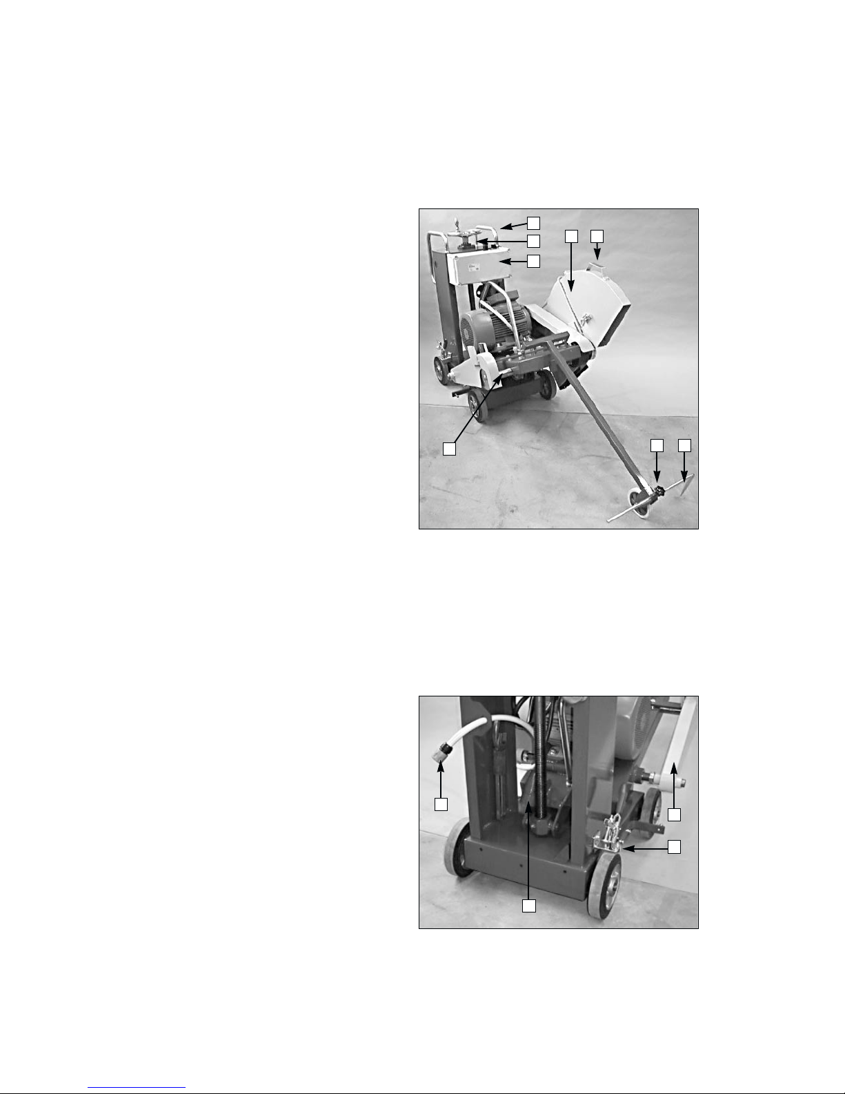
• Check that the water-cooling coupling matches the speci-
fications. See section 9 Technical specifications.
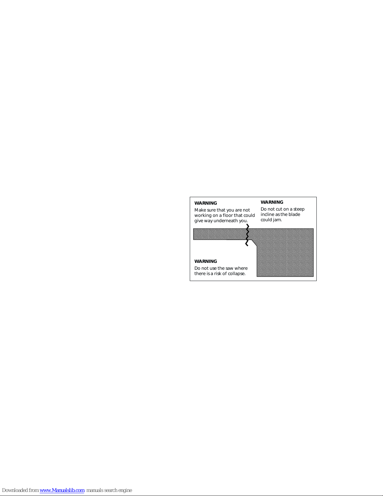
• Set up a barrier or signs around the working area to
prevent any unauthorised personnel from being injured
or disturbing the operator while working.
• Check the belt tension as described in section 5.5. Adjust
if necessary using the belt tensioning screw. Turning
clockwise tightens the belts.
• Before you start cutting, plan your work and clearly mark
out the area you intend to cut so that you can carry out
thework without riskofinjury or damagetothe machine.
See figure 3.1.
• To avoid interruptions and inconvenience during cutting,
planyourwork so that youfittheblade on the mostsuita-
ble side of the saw right from the start.
• Check that you have the correct diamond blade for the
FS800 E/EM and the material you intend to cut. See
section 9 Technical specifications.
• Check the direction of rotation before fitting the blade.
Raise the blade guard on the side where you want to fit
the blade. Secure the blade guard with the retaining
strap. Connect the power cable and press the switch to
start the machine. Check that the blade flange rotates in
the direction shown by the arrow on the blade guard. If
the flange rotates in the wrong direction, turn off the
switch to stop the machine, then unplug the power cable
from the machine. Turn the phase inverter in the socket.
Stop the machine as described above and recheck.
• Check that the blade is not worn; each of the diamond
segments must project at least 1 mm. They must also be
wider than the body of the blade. See figure 6.3.
• Check that none of the diamond segments is damaged.
• Fit the blade so that the arrow on the body of the blade
matches the direction of rotation of the shaft. Tighten
the blade flange using the pin spanner supplied, while
using the other spanner to prevent the blade shaft from
turning. See the instructions in section 6, Fitting and
replacing diamond blades. See figure 6.1.
• Lower the blade guard over the blade.
• Check that the blade is straight by turning the blade by
hand and measuring the gap between the blade and the
blade guard. If the blade is misaligned or uneven it must
be replaced.
• Check that both the blade guard and the blade flange
guard are correctly fitted, then lower them.
• Make sure the emergency stop is not deactivated. The
emergencystop must not bedeactivatedduring operation.
• Before starting the floor saw, raise the blade so that it
rotates without touching the surface.
• Connect the power cable to the power socket.
• Connect the water-cooling hose to the coupling that runs
from the blade guard.
• Check that the water supply is adequate and that the
nozzle is not blocked.
• Make sure that the power cable and water-cooling hose
from the floor saw will not get trapped underneath or in
front of the machine when you start up or during cutting.
• Use the safety equipment specified in the safety precau-
tions on page 5.
Figure 3.1.
4. Starting and operating
Before starting and operating the saw follow the steps in
section 3.
• Lower the alignment guide and adjust it so that the tip of
the guide and the saw blade are in line.
• Release the parking brake.
• Line up the floor saw with the cutting line you have
marked on the floor.
• Clear away any objects from the path of the machine that
could damage the machine or the surroundings.
• Check that there are no unauthorised people inside the
working area, i.e. 4 metres in front of and to the side of
the machine.
• Make sure that anyone who has to remain nearby is
wearing hearing protection.
• Check that the saw blade rotates freely.
___________________________________________________________________________________________________________________________________________________________________________________
;;;;;;;;;;;;;;;;;;;;
;;;;;;;;;;;;;;;;;;;;
;;;;;;;;;;;;;;;;;;;;
;;;;;;;;;;;;;;;;;;;;
;;;;;;;;;;;;;;;;;;;;
;;;;;;;;;;;;;;;;;;;;
;;;;;;;;;;;;;;;;;;;;
;;;;;;;;;;;;;;;;;;;;
@@@@@@@@@@@@@@@@@@@@
@@@@@@@@@@@@@@@@@@@@
@@@@@@@@@@@@@@@@@@@@
@@@@@@@@@@@@@@@@@@@@
@@@@@@@@@@@@@@@@@@@@
@@@@@@@@@@@@@@@@@@@@
@@@@@@@@@@@@@@@@@@@@
@@@@@@@@@@@@@@@@@@@@
ÀÀÀÀÀÀÀÀÀÀÀÀÀÀÀÀÀÀÀÀ
;;;;;;;;;;;;;;;;;;;;
;;;;;;;;;;;;;;;;;;;;
;;;;;;;;;;;;;;;;;;;;
;;;;;;;;;;;;;;;;;;;;
;;;;;;;;;;;;;;;;;;;;
;;;;;;;;;;;;;;;;;;;;
;;;;;;;;;;;;;;;;;;;;
;;;;;;;;;;;;;;;;;;;;
yyyyyyyyyyyyyyyyyyyy
WARNING
Make sure that you are not
working on a floor that could
give way underneath you.
WARNING
Do not cut on a steep
incline as the blade
could jam.
WARNING
Do not use the saw where
there is a risk of collapse.

7
• Check your safety equipment and any protective clothing
you are wearing.
• Apply the parking brake.
• If the machine is fitted with a base plate (optional acces-
sory). Lower the base plate by raising the safety catch.
• Turn on the cooling water to provide adequate cooling
and prevent dust formation.
• Release the parking brake, while holding the guide hand-
le on the machine with your other hand.
• Turn the height adjustment wheel clockwise to lower the
blade to a depth that is suitable for the material you are
cutting, but no less than 20 mm.
• Cut a guide slot at this depth, moving steadily along your
marked line. When you have completed the guide slot,
turn the wheel to raise the blade, turn off the cooling
water and stop the saw by pressing the red switch. Drag
the machine back to the starting point.
• Realign the floor saw with the guide slot with the aid of
the alignment guide, then start the machine as described
above.
• Lowerthesaw blade to a suitable depth.Therightcutting
depth depends on the composition of the floor and the
cutting speed. Generally, if the floor saw tries to climb up
out of the slot then the cutting depth is too deep and/or
the cutting speed is too high. The floor saw must not be
advanced so fast that the blade tries to climb out of the
slot. Adjust the cutting depth.
• Advancethemachine smoothly and methodically, making
sure that the alignment guide always follows the guide
slot.
5. Maintenance
NOTE!Alwaysdisconnect the power cables before carryingout
any maintenance, repairs or servicing.
• Cleanthe machine after completing a series of cuts. Note!
Avoid spraying water at the electric motor and wiring.
• Lubricate the blade shaft bearing at the end of each day's
use. During intensive cutting the blade shaft must be
lubricated several times a day. Always use high quality
water-resistant grease.
• Lubricate all other grease points at least once a week, or
more often if necessary. See figures 5.1.1-4 and 5.4.1-2.
Grease the wheel bearings as necessary. See figure 5.1.5.
• The safety devices are provided for your safety, so it is
extremely important that you check all safety equipment
regularly. If you discover a fault, contact your supplier.
NOTE! Do not start the saw if you know that any of the
machine's safety devices is faulty.
• Keep the machine's drive belts free of oil, dirt and dust.
Check the belt tension regularly as described below. If the
beltsrequiretensioning,usetheadjusterscrew in front of
the drive motor. Turn this clockwise to tighten the belts.
See figures 5.2.2 and 5.3.
• Check the condition of the diamond blade regularly to
make sure it is not damaged or worn down. Replace the
bladewhen the segments areworndownor have become
narrower than the body of the blade.
• Check that the water supply is working correctly. If not,
clean the nozzle. See figure 5.2.1.
• Regularly check that electrical wiring and couplings are in
good condition and that all screws are tight.
Figure 5.1
5.1.1-4 Bearing housing grease points
5.1.5. Wheel bearings
___________________________________________________________________________________________________________________________________________________________________________________
1 – 4
5

8
Figure 5.2
5.2.1. Water pipe for cooling blade
5.2.2. Belt tension adjuster screw.
5.2.3. Belt guard
Figure 5.3
Figure 5.4
5.4.1-2 Grease points for height adjustment screw
6. Fitting and replacing diamond
blades
WARNING! Before attempting to fix a fault you must make
sure that the power cables are disconnected to prevent the
machine from starting up while you are working.
• Raise the blade guard and secure it with the retaining
strap.
• Clean the blade flanges and the blade shaft.
• Fit the blade. NOTE! Direction of rotation. See arrow on
body of blade.
• Use the smaller of the two spanners supplied to prevent
the blade shaft from turning, and use the larger spanner
to undo or tighten the blade flange nut. See figure 6.1.
• Lower the blade guard.
Figure 6.1
6.1.1. Spanner for holding shaft
6.1.2. Pin spanner for blade flange
6.1.3. Outer blade flange
6.1.4. Diamond blade
6.1.5. Pulley shaft and inner blade flange
6.1.6. Belt guard
6.1.7. Support for blade guard
___________________________________________________________________________________________________________________________________________________________________________________
1
12
7
6
5
3 2 1 4
10–15
3
2

9
Figure 6.2
7. Lifting and transporting the
floor saw
The FS800 E/EM floor saw is fitted with a parking brake, see
figures 7.2 and 7.3, which must be applied when the saw is not
in use and when it is being transported. The floorsaw also
has a lifting eye, figure 7.1, which must be used when lifting
the machine. Dont lift using any other parts, as this could
cause damage to the machine and personal injury. If using
a lifting strap, attach it to the lifting eye so that the mach-
ine cannot tip over during lifting. When transporting the floor
saw,applythe parking brake and use anchorstrapsorthe like
to prevent it from moving about.
Figure 7.1
7.1.1. Lifting eye
Figure 7.2
Figure 7.2. Parking brake applied
Figure 7.3
Figure 7.3. Parking brake released
8. Troubleshooting
WARNING! Before attempting to fix a fault you must make
sure that the power cables are disconnected to prevent the
machine from starting up while you are working.
If there is a fault with the machine check first whether it
matches any of the faults described in the troubleshooting
chart below.
Ifyoucannot localise the fault and itdoesnotmatch any of the
faults described in the troubleshooting chart you should
contact your supplier for additional information.
___________________________________________________________________________________________________________________________________________________________________________________
1
2
3
Segment
Body of blade
Fixing hole
NOTE!
The diamond segments must be wider than the body
of the blade.
1

9. Technical specifications
The table below gives the technical specifications for the
FS800 E/EM floor saw. It is extremely important that you
check these before:
- Choosing a floor saw.
- Choosing and fitting a diamond blade.
- Connecting to the mains supply.
- Choosing a power cable.
- Choosing the cutting depth.
- Transporting the machine.
If you are unsure about the meaning of the technical specifica-
tions or ordering spare parts, please contact your supplier
FS800 E/EM ART. NOS. 50020 AND 50030
Motor rating kw 7.5
Voltage and type of supply V/phase/Hz 400/3/50 or
220/3/50
Power cable REVE 5x2.5
Polarity Europa plug 16 Amp.
Phase inverter in socket
Drive shaft speed rpm 1150
Max. peripheral speed. m/s 63
Max. diamond blade diameter mm 800
Parking brake yes
Base plate optional
accessory
Chain drive optional
accessory
Max. Cutting depth mm 320
Length approx. mm 1500
Width approx. mm 780
Height approx. mm 1120
Weight (excl. blade) approx. kg 220
Noise noise power <101.7
Lw rel. pw
according to ISO
744 dB(A)
Noise noise pressure <84.8
Lp rel. 0µPa at
ear during
operation B(A)
Vibration according to. 0.8 m/s2 (H/A)
ISO 7505
10
___________________________________________________________________________________________________________________________________________________________________________________
FAULT CAUSE REMEDY
Blade turns wrong way. Phases from power cable are inverted. Change polarity using phase inverter.
Drive belt is slipping. Belt is too slack. Adjust belt tension.
Drive belt is worn. Replace the drive belt.
Drive belt is oily. Clean the drive belt.
Motor cuts out. Cutting depth too large. Reduce cutting depth.
Cutting speed too high. Advance more slowly.
Diamond segments are worn. Replace diamond blade.
Electrical fault. Contact a qualified electrician.
No cooling water. Nozzles are blocked. Clean nozzles.
Water pressure low.
Blade gets jammed. Blade is worn. Replace blade.
Cut closing up. Cut smaller sections, or
support from below using props or a jack.
Motor does not start. Electrical fault. Contact your electrician.
Emergency stop activated. Determine cause. When fault is
fixed, pull up emergency stop.
NOTE! Do not start the machine before rectifying the cause of the fault.

11
______________________________________________________________________________________________________________________________________________________________________________________________________________________________________________________________________________________________________________________________________________________________________
Posn. no. Part no. Quantity Description Posn. no. Part no. Quantity Description
1501351301 1Frame
2531072098 2Wheel axle
3531072193 4Wheel FS800 E / FS1000 E
4531072152 8Slow fuse Sga 20
5531072099 4Cover sleeve
6501353701 1Angle
7531072155 1Screw M8x40 M6S 8.8 FZB
8531072144 1Nut M8 M6M GR8 FZB
9531072153 1Screw M8x25 M6S 8.8 FZB
10 531072203 2Bearing UCP 204
11 531072133 4Washer SRB 12.5 FZB
12 531072161 4Screw M12x40 M6S 8.8 FZB
13 531072164 4Screw M12x60 M6S 8.8 FZB
14 531072133 4Washer SRB 12.5 FZB
15 531072205 2Bearing UCP 205
16 531072101 2Guide handle
17 531072159 4Screw M12x30 M6S 8.8 FZB
18 531072102 1Height adjustment screw
19 531072202 1Bearing UCP 205
20 531072160 4Screw M12x35 M6S 8.8 FZB
21 531072133 4Washer SRB 12.5 FZB
22 531072146 4Nut M12 M6M GR8 FZB
23 531072103 1Spacer
24 531072142 2Locking screw M8x10 MSK PGSS
25 531072149 1Tube 6x45 CP
26 531072104 1Height adjustment wheel
27 531072105 1Pin spanner
28 531072192 1Spanner 41 mm
29 531072048 1Pulley shaft 675 mm
30 531072106 1Shaft 30x745
31 531072142 2Locking screw M8x10 MSK PGSS
32 531072107 1Sleeve
33 501352101 1Shaft guard
34 501356501 1Cutting block
35 501353801 1Bracket
36 531072159 2Screw M12x30 M6S 8.8 FZB
37 531072109 1Shaft 235x20
38 501352201 1Motor block
39 531072176 1Electric motor 7.5 kW FS800 E
40 531072052 1Lifting eye
41 531072146 4Nut M12 M6M GR8 FZB
42 531072135 4Spring washer FBB 12.2
43 531072133 4Washer SRB 12.5 FZB
44 531072162 4Screw M12x45 M6S 8.8 FZB
45 531072165 1Screw M16x110 M6S 8.8 FZB
46 531072147 1Nut M16 M6M GR8 FZB
47 531072191 4Drive belt A53
48 531072053 1Motor pulley
49 501352301 1Belt guard
50 531072154 1Screw M8x30 M6S 8.8 FZB
51 501352401 1Angle bracket
52 531072164 4Screw M12x60 M6S 8.8 FZB
53 531072133 4Washer SRB 12.5 FZB
54 501353901 2Angle
55 531072133 4Washer SRB 12.5 FZB
56 531072146 4Nut M12 M6M GR8 FZB
57 531072206 2Bearing UCF 208
58 531072056 1Shaft pulley
59 531072140 2Locking screw M6x10 MSK PGSS
60 531072057 1Wedge 60x12
61 531072058 2Wedge 32x10
62 531072111 1Outer blade flange, left-hand
63 531072059 2Inner blade flange
64 531072112 1Outer blade flange, right-hand
65 501352501 1Blade guard, lower half
66 531072061 2Brush
67 531072113 1Sleeve
68 501352601 1Front blade guard
69 501352701 1Rear blade guard
70 531072199 1Cooling hose 1/2" 1.3 m DFS-
71 531072114 1Catch
72 501352801 1Support for alignment guide
73 531072153 2Screw M8x25 M6S 8.8 FZB
74 531072131 2Washer SRB 9 FZB
75 531072144 2Nut M8 M6M GR8 FZB
76 531072115 1Alignment guide
77 531072116 1Locking screw spec.
78 531072158 1Screw M10x60 M6S 8.8 FZB
79 531072195 1Wheel for alignment guide
80 531072132 1Washer SRB 11FZB
81 531072139 1Locking nut M10 nylon
82 531072180 1Auxiliary contact FS 800E

12
Posn. no. Part no. Quantity Description Posn. no. Part no. Quantity Description
83 531072183 1Relay FS800 E
84 531072169 1Two-position switch
85 531072185 1Emergency stop FS800 E
86 531072178 1Terminal box
Accessories
87 531072172 1Socket 16 Amp FS800 E
88 531072065 1Pulley shaft assembly
89 501383401 1Alignment guide assembly
90 531072117 1Heightadjustment screw assembly
91 531072181 1Control panel assembly FS800 E
92 531072118 1Parking brake
93 531072136 4Allen screw M6x12 MC6 S8.8 FZB
94 501354001 1Base plate mounting
95 501354101 1Base plate
96 531072121 1Base plate shaft
97 531072156 3Screw M10x30 M6S 8.8 FZB
98 531072132 3Washer SRB 11FZB
99 531072138 1Allen screw M8x40 MC6 S8.8 FZB
100 531072144 1Nut M8 M6M GR8 FZB
101 531072122 1Base plate catch
102 531072197 1Chain 3/16" FS800 E/ FS1000 E
103 531072150 1Tube 6x50 CP
104 531072123 1Toothed pulley 3/16" Z15
105 531072124 1Control wheel shaft
106 531072200 2Bearing FL002
107 531072151 2Tube 6x30 CP
108 531072125 1Control wheel shaft
109 531072144 2Nut M8 M6M GR8 FZB
110 531072126 2Knob
111 531072155 2Screw M8x40 M6S 8.8 FZB
112 531072137 4Hex head screw M6x20
MC6 S8.8 FZB
113 531072127 2Chain tensioner
114 531072132 2Washer SRB 11 FZB
115 531072139 2Locking nut M10 nylon
116 531072130 2Washer SRB 7 FZB
117 531072143 2Nut M6 M6M GR8 FZB
118 531072128 1Drive shaft
119 531072129 1Toothed belt 3/16" Z19
120 531072152 2Slow fuse Sga 20
121 531072161 2Screw M12x40 M6S 8.8 FZB
Parts no longer stocked up to serial no. 9414
531072196 4Older version of wheel
531072071 2Older version of wheel axle
531072208 2Rear wheel for drive
52G0708N 2Chain 3/16" DFS-2E/DFS-2EM for drive
531072209 1Drive shaft
531072203 2Bearing UCP 204 for drive
531072210 2Locking spanner for drive
531072211 2Chain tensioner for drive
Accessories
531072068 1Flush cutting flange FS800 E
504006101 1Flush cutting guard FS800 E
___________________________________________________________________________________________________________________________________________________________________________________
Part no. Quantity Description

13

14

www.husqvarnacp.com
5040594-02
2007-06-07
This manual suits for next models
1
Table of contents
Other Husqvarna Cordless Saw manuals
Popular Cordless Saw manuals by other brands

Makita
Makita DJV180 instruction manual

Würth
Würth HKS 18-A Translation of the original operating instructions

Makita
Makita JR001G instruction manual

Milwaukee
Milwaukee M18 2645-20 Operator's manual

Black & Decker
Black & Decker 609747-21 instruction manual

Kingfisher
Kingfisher MGS1815-Li Original instructions