manuals.online logo
Brands
  1. Home
  2. •
  3. Brands
  4. •
  5. Hussmann
  6. •
  7. Freezer
  8. •
  9. Hussmann RL User manual

Hussmann RL User manual

PARTS LIST
Item Quantity Description
RL / RM / RMF RLNI
RLN / RMN RLNIE RLT
1. 5 10 4 Nut Retainer 5/16-18 (Left End Only)
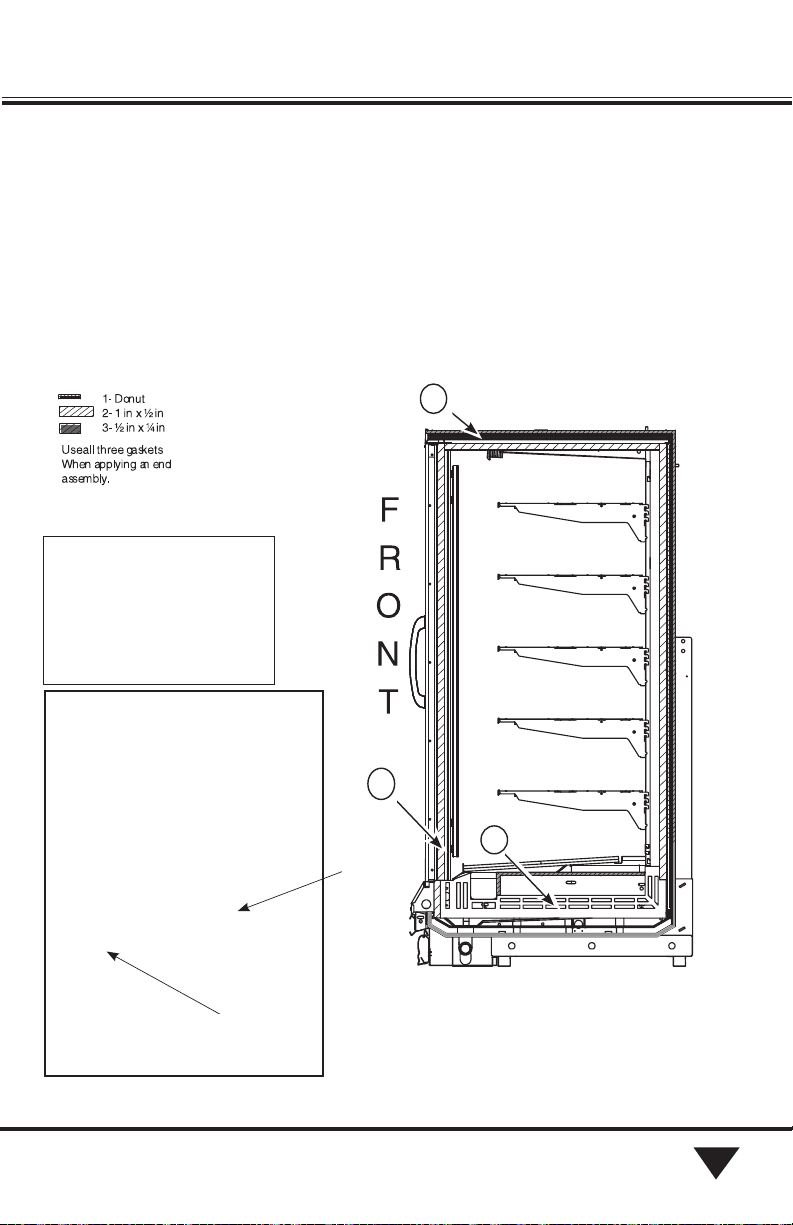
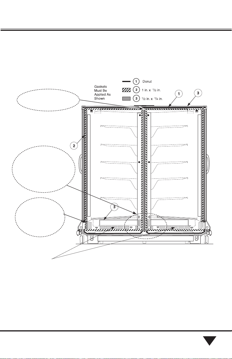
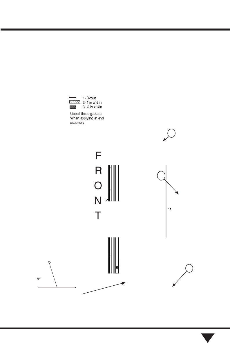
2. 1* 2* 1* Donut Gasket (per end, Ships with Merchandiser)
3. 1** 2** – Gasket
1/2x 1 x 180 in. (4572 mm) (Right End Only)
4. 1** 2** – Gasket
1/4x 1/2in. x 600 in. (15240 mm) (Right End Only)
5. 1 1 1 Gasket Pattern Shoe RH
6. 1 Gasket Pattern Shoe LH
7. 1 1 – End Assembly
8. 6 12 – Cap Screw 5/16-18 x 11/4 in. (32 mm)
9. – – 4 Cap Screw 5/16-18 x 21/2 in. (64 mm)
10. 6 12 5 Plug, Bolt Spacer
11. 6 12 5 Button, Plug 7/8in. diameter
12. – 1 – Trim, Center End
13. 3 11 7 Screw, SM #8 x 1/2 in. (13 mm) Phil AB
14. 6 12 5 Hex Nut 5/16-18
15. – – 1 Cap Screw 5/16-18 x 51/2 in. (140 mm)
16. 1 2 – End ‘J’ Molding
17. 5 10 – Shoulder Screw #8 x 1/2 in. (13 mm) (Innovator Doors)
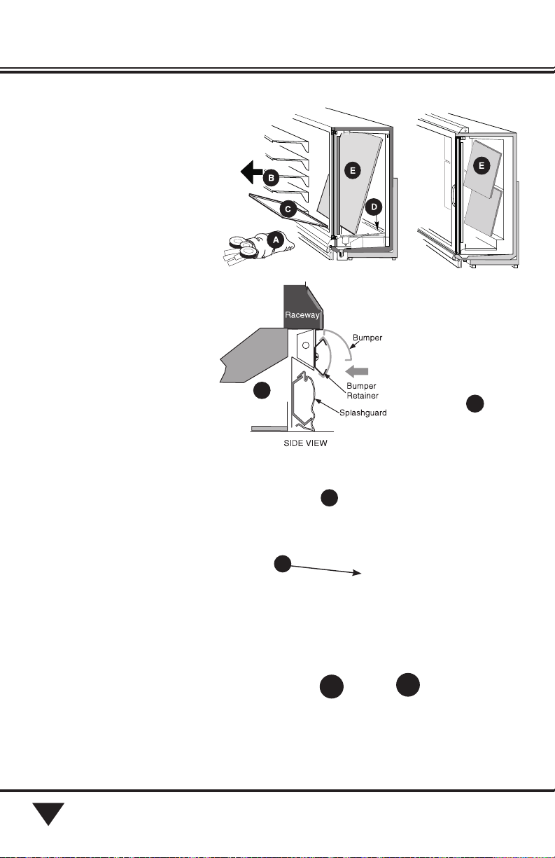
18. – – 1 Bumper End Cover
19. – – 9 Screw, Hex Head SM #8 x 1/2 in. (13 mm)
20. 1 2 1 End Splashguard
21. 1 1 – Starter Bumper (Left End Only)
22. – – 1 End Valance
23. – – 2 End Valance Bracket
Optional End Protector
21. 1 1 1 Protector, End
22. 10 20 10 Screw, Truss Head SM #8 x 1/2 in. (13 mm)
Optional End Bumper
23. 1 1 1 Bumper Retainer
24. 3 5 3 Truss Head Screws
#10 x 1/2 in. (13 mm)
25. 2 2 2 Bumper End Cap
26. 2 2 2 Pan Head Screw
#8 x 11/4 in. (32 mm)
27. 1 1 1 End Bumper
* Donut gaskets are included with merchandiser.
** Left End gaskets are included with merchandiser.
1
HUSSMANN CORPORATION • BRIDGETON, MO 63044-2483 U.S.A.
®
Æ
Frozen Food, Ice Cream, Delicatessen, Dairy & Floral
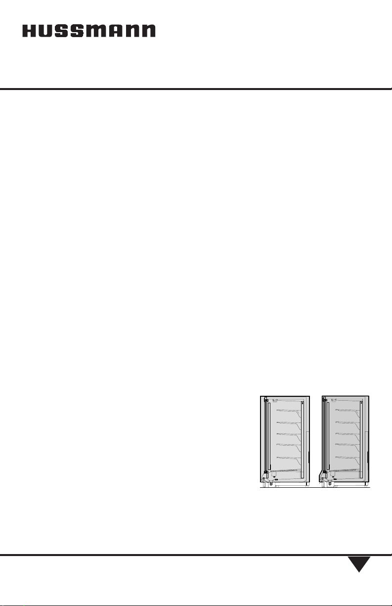
Rectangular Solid or
Contour Glass End for
Reach-In Merchandisers
Installation Instruction
RECTANGULA R ENDCO NTOUR EN D
P/N 0387152_H
May 2015
MANUAL- KIT REACH-IN END
P/N 0387152_H
2HUSSMANN CORPORATION • BRIDGETON, MO 63044-2483 U.S.A.
PREPARATION
Be sure merchandiser has been
leveled according to the installation
instruction. Remove any remaining
shipping braces.
Carefully unpack and inspect the End
kit components. Verify that parts listed
are present and undamaged.
Prepare merchandiser to receive end
(both sides of island) as shown in Figure 1.
A. Remove bumpers, rails, packing
materials, and splashguards.
B. Remove any shelves next to the
end being installed.
C. Remove display racks and pans
next to the end being installed
(both sides of island).
D. Remove rear shelf supports next to
the end being installed (both sides
of island).
E. Remove back panels by lifting up
and out near the bottom. No tools
are necessary.
F. Remove joint molding from door
frames next to the end being
installed (both sides of island).
G. Remove alignment pin, if
installed.
H. RLNI Only: Remove screws and
interior top panel next to the
end being installed (both sides of
island).
Figure 1. Prepare Merchandiser to Receive End
C
A
HH
RLNI Only
F
G
RLT
Reach-in Rectangular Solid
and Contour Glass Ends
P/N 0387152_H
3
HUSSMANN CORPORATION • BRIDGETON, MO 63044-2483 U.S.A.
1For Left-Hand end, install
Nut Retainers – 1 as shown in
Figure 2. If installing a right-
hand end, verify that Nut
Retainers are in place.
For Right-Hand end, remove
alignment pin shown in Figure 3.
Figure 2. Install Nut Retainers
1
RL / RM /
RMF
and
RLN / RMN
RLNI
Figure 3.
Remove Alignment Pin
Alignment Pin
RLT
P/N 0387152_H
4HUSSMANN CORPORATION • BRIDGETON, MO 63044-2483 U.S.A.
2Apply Donut Gasket – 1 in
recess around left end as shown
in Figure 4A, Part 1; 4B or 4C,
Part 1, and right end frames as
shown in Figure 4A, Part 2; 4B
or 4C, Part 2.
Apply the wider Foam Tape
Gasket — 2 around the right
end frame as shown in Figure 4A,
Part2, 4B or 4C, Part 2.
Figure 4A, Part 1. Apply Gasket to Left End of RL/RM/RMF and RLN/RMN
RL / RM / RMF
and
RLN / RMN
Left End Case
Left End Case
Right End Case
1
Use only one Gasket Pad Sealer for each case joining.
Reach-in Rectangular Solid
and Contour Glass Ends
P/N 0387152_H
5
HUSSMANN CORPORATION • BRIDGETON, MO 63044-2483 U.S.A.
Figure 5B, Part 2. Apply Gaskets to Right End of RL/RM/RMF and RLN/RMN
Notes:
1. The perimeter gasket,
Item 3, is required byNSF.
2. Butyl is NOT an acceptable
substitute for donut or foam
gasket.
2
3
Overlap
Gasket
Apply Pad Shoe Sealer first,
then apply the narrower Foam
Tape Gasket — 3 around the
perimeter of the right end frame
outside of the donut gasket as
shown in Figure 5A, Part 2, 5B
or 5C, Part 2.
• Lap gaskets at lower corners.
• Check that there are no gaps
between gasket and case.
• Do not stretch gasket,
especially around corners. To
make sharp corners, paper
backing can be torn without
removing from gasket.
• Do not butt gaskets; always lap
joints.
• Remove paper backing after
gasket is applied to keep gasket
free of debris.
• Gasket has high tack
adhesive and must be properly
placed the first time.
Right End Case
1
Pad Shoe
Sealer
RL / RM /
RMF
and
RLN / RMN
ALL MODELS: Apply
gasket between wipes.
P/N 0387152_H
6HUSSMANN CORPORATION • BRIDGETON, MO 63044-2483 U.S.A.
Figure 5A. Part 1 Apply Gaskets to Left End of RLNI
RLNI
Left End Case
Reach-in Rectangular Solid
and Contour Glass Ends
P/N 0387152_H
7
HUSSMANN CORPORATION • BRIDGETON, MO 63044-2483 U.S.A.
Figure 5B. Apply Gaskets to Right End of RLNI
RLNI Right End Case
Pad Shoe
Sealer
P/N 0387152_H
8HUSSMANN CORPORATION • BRIDGETON, MO 63044-2483 U.S.A.
Figure 5C, Part 1. Apply Gasket to Left End of RLT
Left End Case
Left End Case
Right End Case
1
RLT
Reach-in Rectangular Solid
and Contour Glass Ends
P/N 0387152_H
9
HUSSMANN CORPORATION • BRIDGETON, MO 63044-2483 U.S.A.
Figure 5C, Part 1. Apply Gasket to Left End of RLT
Move the second merchandiser
against first, mating alignment
pins with corresponding holes.
Use care when pushing the cases
together.
RL / RM / RLN / RMN /
RLNI: Do not to cut wires
routed along the front bumper
retainer. See detail in Figure 6.
The RLT has no alignment pin
and the wireway is at the top
front.
Figure 5C, Part 2. Apply Gasket to Right End of RLT
Right End Case
RLT
1
2
3
Apply Pad Shoe
Sealer
P/N 0387152_H
10 HUSSMANN CORPORATION • BRIDGETON, MO 63044-2483 U.S.A.
Bumper Retainer Detail
Figure 5. Exposing the Raceway
SOLID ENDS,
go to Step 11.
RLT Glass Ends,
go to Step 8.
3Glass Ends Only
Glass end assemblies have anti-sweat
heaters. The heater wiring must be
connected to the terminal block in
the wireway. Gain access to the wireway
as follows:
A. Remove bumper if installed.
B. Remove screws from the center of each
bumper retainer and set aside: 2-door,
two screws,
3-door, three screws,
4-door, four screws, or
5-door, five screws. The retainers stay
on the merchandiser. Refer to detail in
Figure 5.
C. Lift the front panel up and out. Tabs on
the front panel must clear slots in bumper
retainers. See Figure 5. Terminal block is
now visible in the wireway.
Once end is installed and all wiring con-
nected, reinstall front panel and screws.
Refer to Section 1 of the Reach-In
Installation and Service Manual to
install bumpers.
Reach-in Rectangular Solid
and Contour Glass Ends
P/N 0387152_H
11
HUSSMANN CORPORATION • BRIDGETON, MO 63044-2483 U.S.A.
Install RLNI Glass End , go to
Step 5.
4Fasten
Glass End Assembly — 5
to merchandiser using
Cap Screw — 6 as shown in
Figure 6.
As the end is being positioned,
route the wiring through the
opening into the wireway as
shown in the Detail.
After end assembly has been
tightened, insert Plug — 7
and Button — 8 as shown in
Figure 6.
Go to Step 7. DETAIL:
Route Wiring into Raceway
Figure 6. Install Glass End Assembly
Route anti-sweat heater
wiring from each end panel
through grommet into race-
way.
For RLNI, route each side
separately, DO NOT damage
wiring
P/N 0387152_H
12 HUSSMANN CORPORATION • BRIDGETON, MO 63044-2483 U.S.A.
RLNI ONLY
5The end panel for the Reach-
in Island ships in two pieces.
Attach the Left Side of Glass
End Assembly — 5 to the
merchandiser using
Cap Screw — 6.
As the end is being positioned,
route the wiring through the
opening into the left-hand
wireway as shown in the
detail.
After end assembly has been
tightened, insert Plug — 7
and Button — 8 as shown
in Figure 7.
Figure 7. Install Left Side of Glass End Assembly on Island
Left Side
Route each side anti-sweat
heater wiring separately
from each panel through
grommet into raceway.
DO NOT damage wiring.
Reach-in Rectangular Solid
and Contour Glass Ends
P/N 0387152_H
13
HUSSMANN CORPORATION • BRIDGETON, MO 63044-2483 U.S.A.
RLNI ONLY
6Position the
Center End Trim — 9 flush
against the installed side and
fasten with Screws — 10 as
shown in Figure 8.
7Once the trim is installed,
attach the Right Side of the
Glass End Assembly — 5
using Cap Screw — 6.
As the end is being posi-
tioned, route the wiring
through the opening into the
right-hand
wireway.
After the end assembly has
been tightened, insert Plug
— 7 and Button — 8 as
shown in Figure 9. Figure 9. Install Right Side of
Glass End Assembly on Island
Figure 8. Install Center End Trim on RLNI Glass End
8
7
6
5
1
Right
Side
Left
Side
Left Side
P/N 0387152_H
14 HUSSMANN CORPORATION • BRIDGETON, MO 63044-2483 U.S.A.
RLT ONLY
8
Glass Ends Only
Glass end assemblies have
anti-sweat heaters. The heater
wiring must be connected to
the terminal block in the
wireway. Gain access to the
wireway as follows:
9Fasten
End Assembly — 5
to merchandiser using
Cap Screw — 6.
After end assembly has been
tightened, insert Plug — 7
and Button — 8 as shown
in Figure 10.
Figure 10. Install Solid End Assembly
Route anti-sweat heater
wiring from end panel
through grommet into
raceway.
DO NOT damage wiring.
Reach-in Rectangular Solid
and Contour Glass Ends
P/N 0387152_H
15
HUSSMANN CORPORATION • BRIDGETON, MO 63044-2483 U.S.A.
RLNI Only: Wiring from the left
end assembly is routed to, and
wired in, the left wireway; wiring
from the right end panel is routed
to, and wired in, the right wire-
way. The RLNI wiring diagram is
per side — two wiring circuits per
merchandiser.
10 Connect anti-sweat
heater wiring to terminal
block according to Figure 11.
Note that grayed information
is standard merchandiser wiring.
11
Solid Ends
Fasten End Assembly — 5
to merchandiser using
Cap Screw — 6. After end
assembly has been tightened,
insert Plug — 7 and
Button — 8 as shown in
Figure 12.
Figure 11. Wire End Anti-Sweat Heaters
Figure 12. Install Solid End Assembly
RL / RM / RMF
and RLN / RMN
P/N 0387152_H
16 HUSSMANN CORPORATION • BRIDGETON, MO 63044-2483 U.S.A.
RLNI ONLY
12 RLNI with solid end:
The end panel for the
Reach-in Island ships in two
pieces. Attach the Left Side
of End Assembly — 5
to merchandiser using
Cap Screw — 6 as shown
in Figure 13. After end
assembly has been tight-
ened, insert Plug — 7 and
Button — 8.
13
Position the
Center End Trim — 9
flush against the installed
side and fasten with Screws
— 10 as shown in Figure 14.
8
7
6
5
1
Figure 14. Install Center End Trim on RLNI Solid End
Figure 13. Install Left Side of Solid
End Assembly on Island
Left Side
Left Side
Reach-in Rectangular Solid
and Contour Glass Ends
P/N 0387152_H
17
HUSSMANN CORPORATION • BRIDGETON, MO 63044-2483 U.S.A.
14Once the trim is installed,
attach the Right Side
of the Solid End Assembly —
5 using Cap Screw — 6. After
end assembly has been tight-
ened, insert Plug — 7 and
Button — 8 as shown in
Figure14.
All Ends Except RLT:
15 Fasten
End Assembly — 5
at the lower front using
Cap Screw — 6 and
Nut — 11 as shown in Figure
16A. Insert Plug — 7 and
Button — 8.
RLT:
Fasten End Assembly — 5
at the lower front using
Cap Screw — 12 and
Nut — 11 as shown in
Figure 16B. Insert Plug — 7
and Button — 8.
8
7
6
1
5
5
Figure 15. Install Right Side of Solid End Assembly on Island
Right
Side
Left Side
11
5
RLT End
7
12
8
Figure 16B. Fasten Lower Front – RLT
7
6
8
12
Figure 16A. Fasten Lower Front – ALL Models Except RLT
P/N 0387152_H
18 HUSSMANN CORPORATION • BRIDGETON, MO 63044-2483 U.S.A.
16 Innovator and
Innovator II doors
only: Insert End ‘J’ Molding
– 13 between door frame
and end assembly. Align
holes in molding with holes
in door frame then insert
Shoulder Screws – 14 as
shown in Figure 17.
17 Align End
Splashguard – 17
with front splashguard as
shown in Figure 18. Fasten
to end frame of merchandis-
er using Screws – 10.
Cut overlapping splash-
guard to fit (see Figure 18
detail).
RLT Only.
18 Attach the
Bumper End Cover
– 15 on the merchandiser
front bumper retainer using
Screws – 16 as shown in
Figure 19. Note: the RLT
has no starter bumper.
13
14
13
14
Figure 17. Install ‘J’ Molding
Figure 18. Install End Splashguard
17
10
17
DETAIL If front splashguard is plastic, trim
to align with End Splashguard.
15
16
Figure 19.
Install Bumper End
Cover
Reach-in Rectangular Solid
and Contour Glass Ends
P/N 0387152_H
19
HUSSMANN CORPORATION • BRIDGETON, MO 63044-2483 U.S.A.
19 Left End Only: Install
Starter Bumper – 18
on the merchandiser front
bumper retainer as shown in
Figure 20, and in Section 1 of
the merchandiser installation
manual.
RLT Only.
20Attach the
End Valance – 19 and
End Valance Brackets – 20 to
the merchandiser using
Screws – 16 as shown in
Figure 21.
Install
Optional End Protector
21Fasten
End Protector – 21
to end using Screws – 22.
Screw locations will vary with
tread pattern. See Figure 22.
Figure 22. Install Optional
End Protector
Figure 20. Install Starter Bumper
Right End of RLT
Left End of RLT
16 16
16
16
19
20
20
19
Figure 21. Install RLT Valance
P/N 0387152_H
20 HUSSMANN CORPORATION • BRIDGETON, MO 63044-2483 U.S.A.
Install
Optional End Bumper
1Position Bumper Retainer –
23 against End Assembly as
shown in Figure 23 and check
for level. Refer to Figure 24
to determine placement.
Glass Ends: Position of center
screw may be offset so that
internal wiring is not dam-
aged. Fasten through center-
line groove with Screws – 24.
2Place rear Bumper End Cap
– 25 over Retainer and slide
the End Cap forward until
it stops. Fasten using Screw
– 26.
3Slide End Bumper – 27
into Bumper Retainer and
back against End Cap.
4Place front
Bumper End Cap – 25
over Retainer and under
Bumper. Mark location of
front of end cap. Remove end
cap and slide the bumper off.
Slide the front bumper end
cap to mark and fasten with
Screw – 26.
5Hook the End Bumper – 27
over the retainer and push
down until it engages, front
to back.
Figure 23. Install Optional End Bumper
25
26
25
26
23
27
24
25
26
Glass Ends: Position of center screw may be offset
so that internal wiring is not damaged.

Other manuals for RL

1

This manual suits for next models

7

Other Hussmann Freezer manuals

Hussmann IMPACT Excel D5XRRIS Instruction Manual

Hussmann

Hussmann IMPACT Excel D5XRRIS Instruction Manual

Hussmann SM-110 User manual

Hussmann

Hussmann SM-110 User manual

Hussmann FMSS-L Instruction Manual

Hussmann

Hussmann FMSS-L Instruction Manual

Hussmann impact Excel C2X-XGE Instruction Manual

Hussmann

Hussmann impact Excel C2X-XGE Instruction Manual

Hussmann ARV-01050 Operation Quick start guide

Hussmann

Hussmann ARV-01050 Operation Quick start guide

Hussmann RL User manual

Hussmann

Hussmann RL User manual

Hussmann HBD/BC-142 User manual

Hussmann

Hussmann HBD/BC-142 User manual

Hussmann impact Excel C2X-XGEP Instruction Manual

Hussmann

Hussmann impact Excel C2X-XGEP Instruction Manual

Hussmann impact Excel B3XC-LGEP Instruction Manual

Hussmann

Hussmann impact Excel B3XC-LGEP Instruction Manual

Hussmann IMPACT C2-XEP Instruction Manual

Hussmann

Hussmann IMPACT C2-XEP Instruction Manual

Hussmann ARV-650S User guide

Hussmann

Hussmann ARV-650S User guide

Hussmann 10HD Quick guide

Hussmann

Hussmann 10HD Quick guide

Hussmann DCCG-8 User manual

Hussmann

Hussmann DCCG-8 User manual

Popular Freezer manuals by other brands

Waeco CF-80 instruction manual

Waeco

Waeco CF-80 instruction manual

Follett ZF130 SLIM Operation and maintenance manual

Follett

Follett ZF130 SLIM Operation and maintenance manual

Nordcap NC41N manual

Nordcap

Nordcap NC41N manual

Taylor C707 Operator's manual

Taylor

Taylor C707 Operator's manual

Zanussi ZFC321WA user manual

Zanussi

Zanussi ZFC321WA user manual

Smeg VR105AP1 operating instructions

Smeg

Smeg VR105AP1 operating instructions

Zanussi ZC190F Instruction booklet

Zanussi

Zanussi ZC190F Instruction booklet

Haier JQ-F110C user manual

Haier

Haier JQ-F110C user manual

Soren CS 800 instruction manual

Soren

Soren CS 800 instruction manual

Electrolux EN3614AOW user manual

Electrolux

Electrolux EN3614AOW user manual

Unique UGP-175L R AC owner's guide

Unique

Unique UGP-175L R AC owner's guide

Sanyo MDF-593 instruction manual

Sanyo

Sanyo MDF-593 instruction manual

Zanussi DF36 Instructions for use

Zanussi

Zanussi DF36 Instructions for use

Frigidaire FFU14M8H Factory parts catalog

Frigidaire

Frigidaire FFU14M8H Factory parts catalog

Frigidaire FFC13K1AW1 Factory parts catalog

Frigidaire

Frigidaire FFC13K1AW1 Factory parts catalog

Gram FS 3215-93/1 user guide

Gram

Gram FS 3215-93/1 user guide

Frigidaire FFC15C2CW0 Factory parts catalog

Frigidaire

Frigidaire FFC15C2CW0 Factory parts catalog

Haier HRF360TS User instructions

Haier

Haier HRF360TS User instructions

manuals.online logo
manuals.online logoBrands
  • About & Mission
  • Contact us
  • Privacy Policy
  • Terms and Conditions

Copyright 2025 Manuals.Online. All Rights Reserved.