OPERATING PROCEDURES
LEVELING PROCEDURE
2. Turn ignition switch to "ACCESSORY".
3. Push the "ON/OFF" switch to the "ON" position.
The POWER ON light will be lit. 7. Push the "ON/OFF" switch to the "OFF" position.
8. Turn the ignition switch off.
month or whenever the vehicle is used, to keep the
system in operating condition.
6. After the vehicle is level, the jacks not used for leveling
may be extended until they touch the ground. This provides
additional stability against wind and activity in the vehicle.
Do this by pushing the jack control lever to the rear and/or
front as needed to extend any remaining jacks. Do not use
PARK/BRAKE" light will come on when the "ON/OFF"
switch is on. The pump will not run if the park brake
4. Move the FRONT and REAR STORE LEVERS to the OPERATE
POSITION. Nothing should happen at this time. Place pads
under jacks if necessary at this time.
ROOM EXTENSION PROCEDURES
extension read this section carefully.
If the vehicle is equipped with kick-down jacks, the wheels MUST
be blocked securely. Do NOT operate any room extension
until the leveling and stabilizing procedure is complete. Do
IMPORTANT: If the vehicle is equipped with a room
NOT retract the leveling system until all room extensions are
retracted. NEVER operate the leveling system when any
Refer to the vehicle owner’s manual for proper operation of
room extensions are extended.
room extensions.
IMPORTANT: Do not use a room extension support when
the vehicle is supported by the leveling system.
1. Place gear selector in the parking position, apply the park
brake and block tires securely.
not have enough stroke to level the vehicle. The vehicle may
raise a low corner. If the ground is too uneven, the jacks may
take several movements from side to front, or side to rear to
jack pairs accordingly until all yellow lights are out. It may
extend jack pairs corresponding to a lit yellow light. Extend
Move the JACK CONTROL LEVER to the extend position to
should be lit at at a time. If a corner of the vehicle is low,
corner of the vehicle is low. Only one yellow LEVEL light
5. A lit yellow LEVEL light indicates that the end, side or
a side LEVEL light will be on by itself.
NOTE: If the hand/auto park brake is not set, the "NOT IN NOTE: The leveling system should be cycled once a
NOTE: The respective red WARNING LIGHT will come
on when a jack is extended 2 or more inches.
have to be moved.
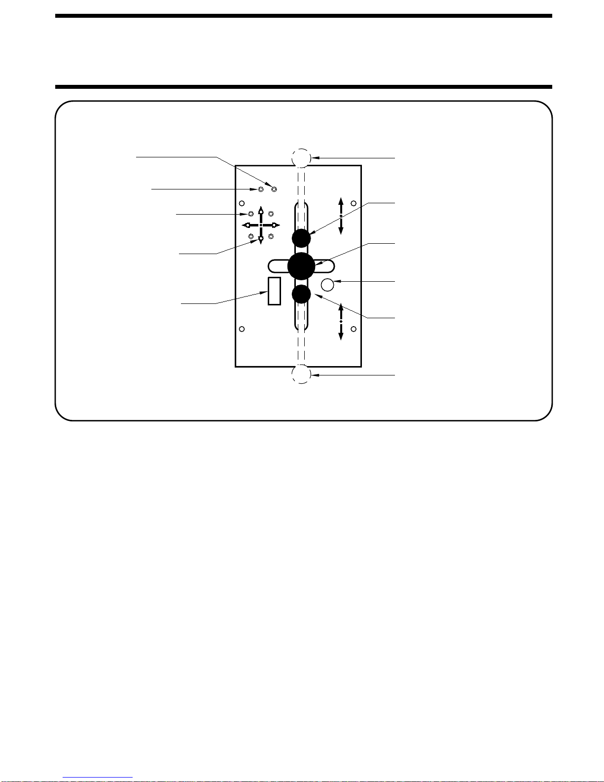
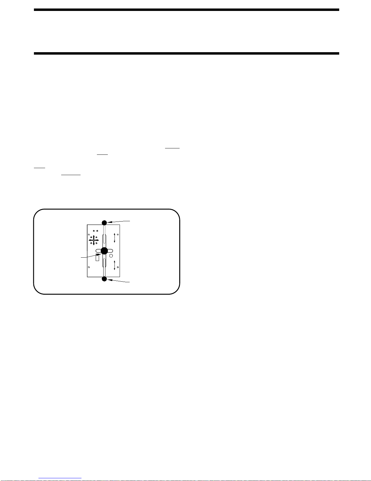
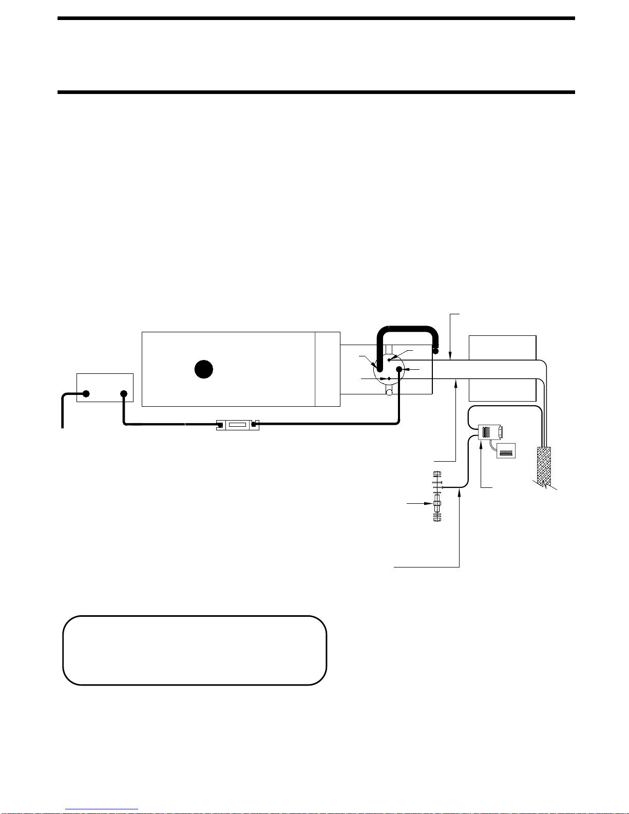
JACK
LEVER POSITIONS
CONTROL
LEVER
FRONT
STORE
LEVER
REAR
STORE
LEVER
LEFT RIGHT
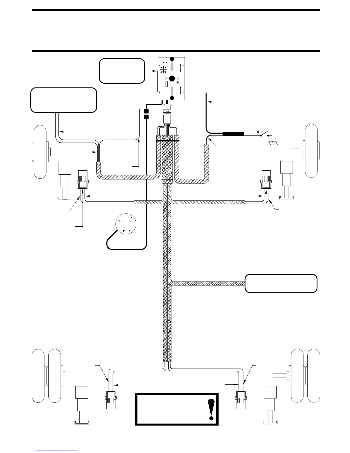
CAUTION!
UNDERSTAND OPERATOR’S MANUAL BEFORE USING.
BLOCK FRAME AND TIRES SECURELY BEFORE
REMOVING TIRES OR CRAWLING UNDER VEHICLE.
ON
OFF
EXTEND
REAR
REAR
OPERATE
FUSE
STORE
5 AMP
FRONT
STORE
HYDRAULIC LEVELING
ON
EXTEND
EXTEND
FRONT
HWH
NOT IN
EXTEND
PARK/
BRAKE
OPERATE
MP35.2015
03FEB03
OPERATE POSITION
is not set.
be dumped from the suspension before proceeding.
NOTE: If the vehicle has an air suspension the air must
the right or left extend positions.
SITE SELECTION
move in any direction due to jack extension or retraction,
room extensions, awnings, doors, steps, etc. Vehicle may
Maintain adequate clearance in all directions for vehicle, If parking on soft ground or asphalt paving, wood blocks or
settling of jacks or vehicle, equipment malfunction, etc.
pads should be placed under the jacks.