Hy-Gain HG-52SS User manual

HG-52SS
52 Foot Self-Supporting Tower
ORDER NO, 125-1
NOTICE
All rights in this publication are reserved. No part of the publication
may be reproduced in any manner whatsoever without the expressed
written permission of Hy-Gain.


CHAPTER 1- GENERAL INFORMATION......:.........................................:.....................1-1
General Description.................................. ....................................................................1-1
Unpacking and Uncrating..................................................................................................1-1
Specifications..........................................................................................................….......1-1
Equipment Supplied............................................................................................................1-1
Equipment Required But Not Supplied....................................................................…......1-2
CHAPTER 2
Safety Precautions...........……..........................…….................................................................2-1
General Safety Rules........................................................................................................2-1
Site Selection ....................................................................................................................2-2
CHAPTER 3
INSTALLATION PROCEDURES ............................................................................. 3-1
Checking Base Foundation Assembly...............................................................................3-1
Planning Your Procedure ..................................................................................................3-2
Foundation..........................................................................................................................3-2
Wood Forms Construction...................................................'......................................... _..3-3
Attaching Tower to Base Plate...........................................................................................3-6
Lightning Protection...........................................................................................................3-9
Tower Maintenance.............................................................................................................3-9
Raising and Lowering Tower ..........................................................................................3-9
Procedures for Freein
g
Bindin
g
Tower Section...................................................................3-9
CHAPTER 4 - INSTALLATION INSTRUCTIONS
FOR ROTATOR AND MOUNTING PL.A.TE.........................................................................4-1
General ............................................................................................................................4-1
Rotator Installation..................................................................................................._......4-1
Parts List..........................................................................................................................4-4
LIST OF ILLUSTRATIONS
Fi
g
ure Pa
g
e
1 Overall View of HG-52-SS Tower.................. ............................................ i
2 Safe Location of Tower..................................................................,.......... 1-2
3 Checking Base Foundation Assembly........................................................3-1
4 Digging Hole for Foundation..................................................._.............._.3-2
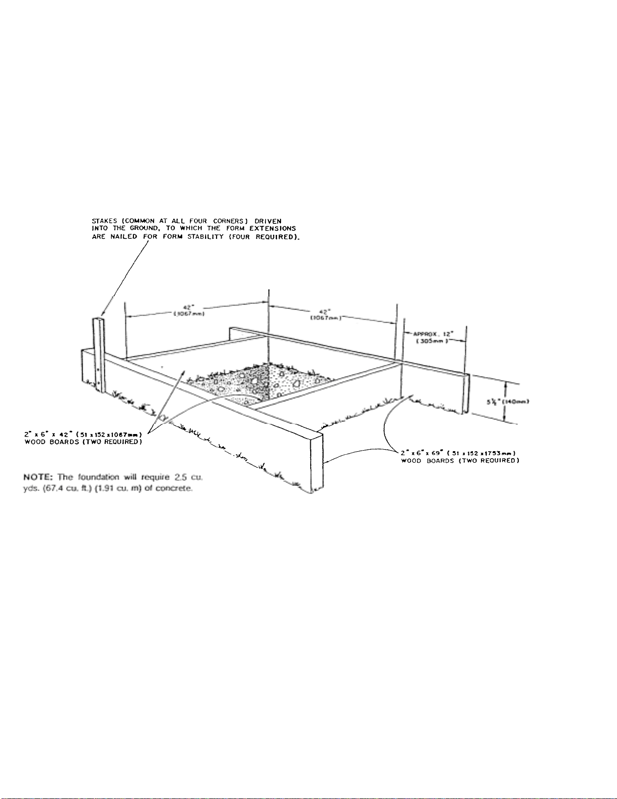
5 Constructing Frame for Concrete Base.........................................................3-3
6 Top View of Foundation Structure Assembly ..............................................3-4
7Han
g
in
g
Base Foundation from Forms ...... ........................................ ....... 3-4
8 Attaching and Leveling Base Frame to Wood Forms ......................... ....... 3-5
9 Tower Foundation ..............................................................................................3-6
10 Attaching Tower to Base Tabs....................................................................... ...3-6
11 Su
pp
ortin
g
Tower While Attachin
g
Related Products...................... ...... 3-7
12 Constructing Gin Pole...................................................................................._..3-7
13 Attaching Winch Assembly to Tower ......................................................... -....3-8
14 Connecting Cable to Winch .................._........................................................3-8
15 Freeing Binding Tower ._............_..................................................................3-10
16 Removable Brace............................................._.............._...............................4-1
17 Typical Installation of Rotator Mounted Below Plate .......................................4-2
18 Typical Installation of Rotator Mounted Above Plate ............................... . -4-2
19 Tower with Call-Outs of all Parts .......................... ...... .... ....... .............4-3

CHAPTER 1
GENERAL INFORMATION
t
WARNING
Installation of this product near power lines
is dangerous. For your safety follow the
instructions.
General Descri
p
tion
The HG-52SS is a 52 foot, self-supporting
tower designed to support 9.5 square feet of
antenna area with winds up to 50 mph. This all
steel tower has a guide system that allows the
tubing to be open at each end insuring
complete galvanizing and total moisture
drainage.
Un
p
ackin
g
and Uncratin
g
Be sure to check your tower form any freight
damage or missing parts. If you find damage,
notify the trucking line that delivered the
equipment immediately, and advise Hy-Gain
of the damage. Send a copy of the freight
damage claim to:
Hy-Gain
308 Industrial Park Road
Starkville, MS 39759
The tower can be extended from its nested
position by manual crank or the use of an
electric motor. A thrust bearing can be bolted
to the to
p
section allowin
g
a 2" diameter mast.
E
q
ui
p
ment
The HG-52SS tower is supplied complete, in-
cluding reinforcing steel and base mount. The
tower corresponds to the drawings contained
in this manual. Refer to the Parts List section
for a complete breakdown of parts.

The Parts List shows the standard
commercial packaging. Any changes or
modifications, if any, which may be
incorporated as the result of special contractual
agreements are covered under Contract
Requirements, but only when applicable.
Equipment Required But Not Supplied

CHAPTER 2
SAFETY PRECAUTIONS
WARNING
Before you start installation of your tower
let us warn you of the danger of letting any
part of your metal tower system touch
electrical power lines -YOU MAY BE
KILLED!
GeneralSafetyRules
8. Don't climb tower; use separate ladder or
lower tower with gin pole for antenna
rotator servicing.
9. Don't overload. The design load limit is
9.5 square feet of antenna on a two foot
mast for winds u
p
to 50 MPH.
Hundreds of people are killed each year
because they don't use common sense when
they install their towers or antennas. It
happens more often than you realize. Someone
falls off a roof or gets electrocuted by
touching a power line with an antenna tower
or metal ladder.
There is no such thin- as a good tower site if it
near electrical power lines. Unfortunately,
iiiost tower systems, and in many cases, the
ladders used during an installation are metal. If
any metal tower part or ladder touches a power
line, it completes an electrical path from the
power line through the metal tower and the
installer (YOU!).
DO'S
1. Do install the tower away from power
lines. Check the distance to the power
lines before you start installing - we
recommend you stay a minimum of-
twice the maximum length of the tower
assembl
y
awa
y
from all
p
ower lines.
2. Do install the tower on a calm day and
assure yourself of having plenty of
da
y
li
g
ht to com
p
lete installation.
3. Do stay clear if the tower starts to fall
or come in contact with
p
ower lines.
DON'TS 4. -Do call the power company to remove
fallen towers from power lines or to
h
e
l
p
p
i
c
k
out
a
sa
f
e
a
n
te
nn
a
s
i
te.
4. Don't try to catch the tower if it starts to
fall
5
6
Don't try to remove any metal objects
from the
p
ower lines.
Don't be afraid to call the power
company for advice when picking a
tower site or removing a fallen tower
froni the power lines.
If someone is accidentally electrocuted, don't
touch him or the tower if he is still in contact
with the tower or downed power lines. Use a
dry stick, like a broom handle or wooden
ladder, etc., and in one sweep push the person
free from the tower or knock the wire away
and off the vi~aiq. Do not allow the wire to
touch the victim again. Have someone call the
power company and an ambulance.
7. Don't remove winch handle; use safety
chain with lock to secure_
5. Do crank tower-down to retracted
position when winds are anticipated to
exceed 50 mph.
1. Don't install any tower near power lines.
2. Don't install a tower on a windy day.

Site Selection
The tower requires a concrete base ap-
proximately 42"x 42" x 5'b" deep. Among
the factors to be evaluated in selecting a
tower site are the types of earth at the
installation site and the nearness of power
lines or overhanging tree limbs.
Soil conditions around the tower foundation l
should allow access to the tower during all
weather conditions.
Figure 2 Safe Location
of Tower

CHAPTER 3
INSTALLATION PROCEDURES.
Checking Base Foundation Assembly
IMPORTANT:
For proper alignment, the tabs on the tower
base foundation assembly must correspond
with the tabs on the tower_
During shipment or while in storage, damage
may have resulted to the tabs on the tower
base foundation assembly_
Before installation of this tower, check
proper alignment of the tabs. To do this, set
the tower horizontally ou two supports. Attach
the base foundation assembly to the tower
using the 3/4" hardware, as shown below.
If the tabs on the base foundation assembly
are out of alignment, use a large hammer to
realign.
Figure 3 Checking Base Foundation
Assembl
y

Planning Your Procedure t,
Good planning is a key to a successful and safe
tower installation_ If you're not sure about a..
careful, safe installation, do not try to do it your-
self. Call for professional help (Yellow Pages
under Towers or
y
our local
p
ower com
p
an
y)
.
The tower should be as close as possible
to.its related equipment. Determine the best
possible site while thinking about power lines,
but also think about overhanging tree limbs that
may be blown into the tower during high
winds.
Foundation
Dig a hole 42" square by 5'6" deep, as shown
in Fi
g
ure 4.
TO
-
0123
-
8
-
001
Figure 4

Wood Forms
Construct a wooden frame around the hole to
support the base assembly as shown in Figure
5.
A sample would be the 2"x4", which after
being dried and planed will measure 1 1/2" x 3
1/2" (3.81 x 8.89 cm), or a 2"x 6", which will
measure 1,1/2"x S 1/2"
(
3.81 x 13.97 cm
)
.
In the U.S.A, the dimensions of lumber are
listed, and referred to, as the size after is
roughcut at the sawmill; prior to being dried
p
laned and sold on the market.
Figure 5 Constructing Frame for
Concrete Base
Orient your tower base in the direction your
tower will be raised. The two parallel ears of
the base assembl
y
will be the hin
g
ed side.
Check and realign the tabs, using a large ham-
mer, so they will agree with the dimensions
g
iven in Fi
g
ure 6. --
,
1~MPORTANT: THE TABS ON THE BASE
ASSEMBLY MUST MATCH THE SPACING
DIMENSIONS CALLED OUT IN FIGURE 6.
Drill a 3/4" hole in each cross member in line
with the lower holes in the base assembly as
shown in Fi
g
ure 7.
The tabs on the tower base assembly may
have been knocked out of alignment during
shi
p
ment or while in stora
g
e.

Figure 6 Top View of Foundation Structure
Assembly
Figure 7 Hanging Base Foundation
from Forms

Attach the base assembly to the wood frame
using 3/4" bolts. IMPORTANT: Base frame must-be level-for
tower to raise and lower
p
ro
p
erl
y
.
Using a carpenter's level check all points to
make sure base frame is level.
Figure 8 Attaching and Leveling Base Frame to
Wood Forms
Pour concrete carefully into hole. Make
certain base assembly maintains the proper
clearance from the outside edges of the hole.
Refer to Fi
g
ure 9.
The concrete shall be designed to provide a
minimum 28 day strength of 2000 PSI and
shall contain not more than 71/2 gallons of
water per sack of cement.
After concrete is poured, check base
assembly making sure it is level and it hasn't
shifted durin
g
the
p
our.
If the base is not level, tape the ears of the
base with the hammer to level.
Let the base cure for at least one week before
settin
g
tower!

Attaching Tower to Base Plate
Set your tower on the hinged side of the
base, align the bottom holes of the tower
with the bottom holes in the base assembly.
Install a single 3/4"bolt in each of the two
parallel base ears. See Figure 10.
TOP V I
SIDE VIEW
Figure 9 Tower
Foundation
Figure 10 Attaching Tower
to Base Tabs
Support the tower on a support, ,like a
sawhorse, and attach your antenna and/or
rotator to the tower before raising the tower as
shown in Figure 11. The support should not
have any sharp edges that may come into
contact with the winch cable.
The use of a thrust bearing, HG=TBT, l i rder
No. 121-B, is recommended for use on t :is
tc;wer if the combined weight of the antenna,
mast, and rotator is greater than 150 pounds.
The use of this thrust bearing is also
recommended on all systems used in areas
where ice load;-.o'may be experienced.

Figure 11 Supporting Tower While Attaching
Related Products
Lift tower into place with gin pole, block and
tackle as shown in Fi
g
ure 12.
Ov
£
~~HG EpR POVE: ~-
EZ.Sa..l woE, ~Yi
l) ec l DEEV
--vV~C00
'
.rES -
"
ED ON - 5.15 t
i
2•a-+
Figure 12
Constructing Gin
Pole
After tower is up, put all base bolts in place
and secure tower in vertical
p
osition
3

Attach winch assembly to tower winch plate
as shown in Figure 13.
Connect the cable to the winch as shown.
Figure 14 Connecting
Cable to
-
Winch

Lightning Protection
To protect your installation and your radio
equipment, the tower system must be properly
grounded. Drive a 4'-8' ground rod as close as
)ossible to the tower structure. Then connect a
#8 (or larger) copper or aluminum wire be-
tween.the base of the tower and the ground
rod.
Tower
To maintain proper and safe operation inspect
and lubricate your tower at least once a year;
more often if subject to heavy or frequent use.
Always be sure your tower is in the retracted
position before attempting any maintenance
procedures.
Inspect all bolts for tightness including cable
termination
,
winch and base bolts.
Releasing the winch handle, the tower sections
will remain in position. Turning the handle in
the counterclockwise position will lower the
tower section(s). When: lowering the tower se
~tion(s) the winch will not make a clicking
sound.
To stop the sections at any height when lower-
ing, turn the winch handle clockwise until you
hear two clicks. This will add extra tension to
the brake mechanism.
If the winch does not operate as described, see
the section titled "Winch Maintenance."
To raise the tower to full height, continue
turning the handle clockwise until your tower
end stops. DO NOT try to crank the winch
tighter if the end stops or any obstruction
sto
p
s tower
_
raisin
g
.
Inspect raising cables and replace if
excessivel
y
:inked or fra
y
ed.
Inspect pulleys and pins for excessive wear
and re
p
lace as re
q
uired.
Place a few drops of light machine oil on all
p
ulle
y
bearin
g
s.
To prevent unauthorized use of the winch,
reverse the winch handle and chain it to the
tower. See additional instructions and safety
measures in the winch manual.
Procedures for Freeing Binding Tower
Sections
Some causes for the sections to bind can be:
Refer to winch manual for proper lubrication
of winch L Bent tower braces during shipment or in
and Lowerin
g
Tower
Before cranking the winch to raise the tower,
examine the raising cables to be certain that
they are securely terminated and properly
p
ositioned in the cable sheave
g
rooves.
2. A heavy object has been accidentally
knocked into the tower bracing after in-
stallation is com
p
lete.
3. Excessive wind force can cause a tower
section to bind up and not retract
strai
g
ht in line with the next lar
g
er
The tower should raise with only moderate ef-
fort with the hand crank winch. If excessive
force is required, check again for possible
shipment damage. DO NOT force the tower
up. It may become jarnmed in an extended
p
osition and won't retract under its own
4. Unbalanced antenna or other e
q
ui
p
ment.
5. Foreign objects such as tree limbs, dirt or
ice can reduce clearance between-fee=
bops.
Turn the handle on the winch in a clockwise
direction winding the cable onto the winch
reel. When the tower is being raised, the
winch will
p
roduce a loud clickin
g
noise.

When lowering the tower, simply crank the
winch in the . opposite directiontt: Constantly
check the upper section cables to make sure
they remain taut as the tower is lowered.
A good way to tell is by watching the raising
cable. If any of the cables become slack at any
location, STOP. The tower section is binding
up and must be cleared before lowering
continues.
'' CAUTION:
When cranking the tower down, make sure ;
all sections lower simultaneously.
A second person should watch the lowering
se.ience carefullyto make sure all sections of
the tower lower together.
To correct these problems, crank the tower
back up until the cable is tight. A soft, rubber
faced hammer can be used on the tower legs
while lowering the tower to jar the obstruction
free. If you use a rubber mallet, tap only on the
tower leg where the bracing meets the leg and
tap as far up on the bottom section as you can
reach. NEVER TAP ON ANY TOWER
BRACING! See Figure 15.
Figure 15 Freeing
Bindin
g
Tower

If cable becomes slack again, raise toe tower
to tighten the cable and repeat the procedure.
Another procedure to free binding sections is
to rotate the antenna to a different heading one
or more times. Doing so can help solve the
binding caused by steps 3 and 4 of this
section.
Winch
WinchWinch
Winch
Routine inspection of the winch and
performing preventive maintenance will insure
maximum
p
erformance and unnecessar
y
Check the-winch annually. In wet or dirty en-
vironments check more fre
q
uentl
y
.
If foreign objects must be removed to free the
tower, DO NOT CLIMB THE TOWER! Be
sure all cables are tight before doing so. If
none of the previous methods work to free the
tower, seek professional help. A snorkel or
boom truck can be utilized to inspect, and
correct the cause of the binding. Never leave
the cable slack hoping the tower will free
itself. If it does come free it could collapse
completely, damaging both the tower and the
antenna. All Hy-Gain towers are factory tested
(fully extended and retracted) and inspected
before being shipped, to insure proper
condition.
To increase the life of the winch and for con-
tinued smooth performance, grease the gears,
reel shaft and handle threads (Item N, BB,
and F). Also place a drop of oil on the drive
shaft bearings (Items B and L). Refer to the
Winch Manual.
CAUTION: DO NOT OIL OR GREASE
THE BRAKE MECHANISM (PRESSURE
PLATE). ,
Protecting the finish of the winch will
provide longer service. Wash the winch with
water, dry thoroughly, then wipe with light
oil or wax.

INSTALLATION INSTRUCTIONS FOR
ROTATOR AND MOUNTING PLATE
General This tower is designed to accept most any
style rotator.
The smallest tower section has a removable
brace to allow insertion of the rotator and
rotator mountin
g
p
late.
NOTE: If you are installing the Hy-Gain R-
300 Rotator, you will not be able to nest your
tower completely, doing so may damage the
rotator.
Refer to Figure 15. Loosen the two #10 x
3/4" bolts on each end of the removable
brace. Loosen the two #10 locknuts then
l
oose
n
t
h
e
two
#
1
0
x
3/
4"
bo
l
ts.
CAUTION:
;~ The tower must be cranked up high enough
;; to expose the removable bracing. DO NOT
~; CLIMB THE TOWER! Place a ladder next
;
~
;;
to the tower or la
y
the tower on the
Rotator Installation
* Slide the brace u
p
and out to remove.
For a rotator that installs below the
mountin
g
p
late follow the ste
p
s below
Figure
1. Set the
'
rotator in the tower with the
shaft bearing pointing up. If the mast
brackets or clamps are attached to the
tt hft
they must be
Using the winch, crank the tower high enough
to allow the removable brace to clear the top
of the second tower section by about 3 feet.
You can now either lay the tower down or
leave it up in the vertical position. If you
leave it in the verti
rl position, place two short pieces of 2"x 4"
lumber- in between the braces so the tower
2. Set the rotator mounting plate in the
tower so it will set directly on the three
sto
p
s welded to the inside of each
3. Bolt the rotator to the mounting plate
using the mounting bolts supplied with
the rotator
4
Assemble the rotator-to-mast, mast
p
latform and mast as shown in Fi
g
ure
5
Reconnect the removable brace to its
ori
g
inal
p
osition on tower.

NOTE: For rotators mounted above the
rotator `mounting plate, follow these
instructions and refer to Figure 18.
1. Insert the rotator mounting plate in the
tower so it rests on the mounting plate
sto
p
s.
2. Install the rotator on the mounting
plate. Use the mounting bolts supplied
with the rotator.
3. Loosen the mast clamp so the mast can
be inserted in the clamp.
4. Tighten the mast clamp around the
5. Mount your antenna on the top of -the
mast. If you are using coax anus, tie
your rotator coax to the coax arms.
6. Connect your coax to the radio equip-
ment
7. Reconnect the removable brace to its
original position on the tower section.
Tighten the # 10 hardware securely.
Tighten the #10 x 3/4" bolts and secure
with the #10 hex locknuts.
Figure 17 Typical Installation of
Rotator mounted Below Plate Figure 18 Typical Installation of
Rotator Mounted Above Plate
4
Table of contents
Popular Desktop manuals by other brands

Protech Systems
Protech Systems SA-5700 user manual

Lenovo
Lenovo ThinkSERVER TS130 user guide

Lenovo
Lenovo ThinkCentre 0401 Hardware Maintenance Manual

HP
HP Pavilion x2 12-B100 Maintenance and service guide

HP
HP Workstation xw8000 Hardware installation

Lenovo
Lenovo ThinkCentre A70z ALL-IN-ONE Användarhandbok