CM4UFX - CLUB SERIES PROFESSIONAL MIXERS
PAGE 7
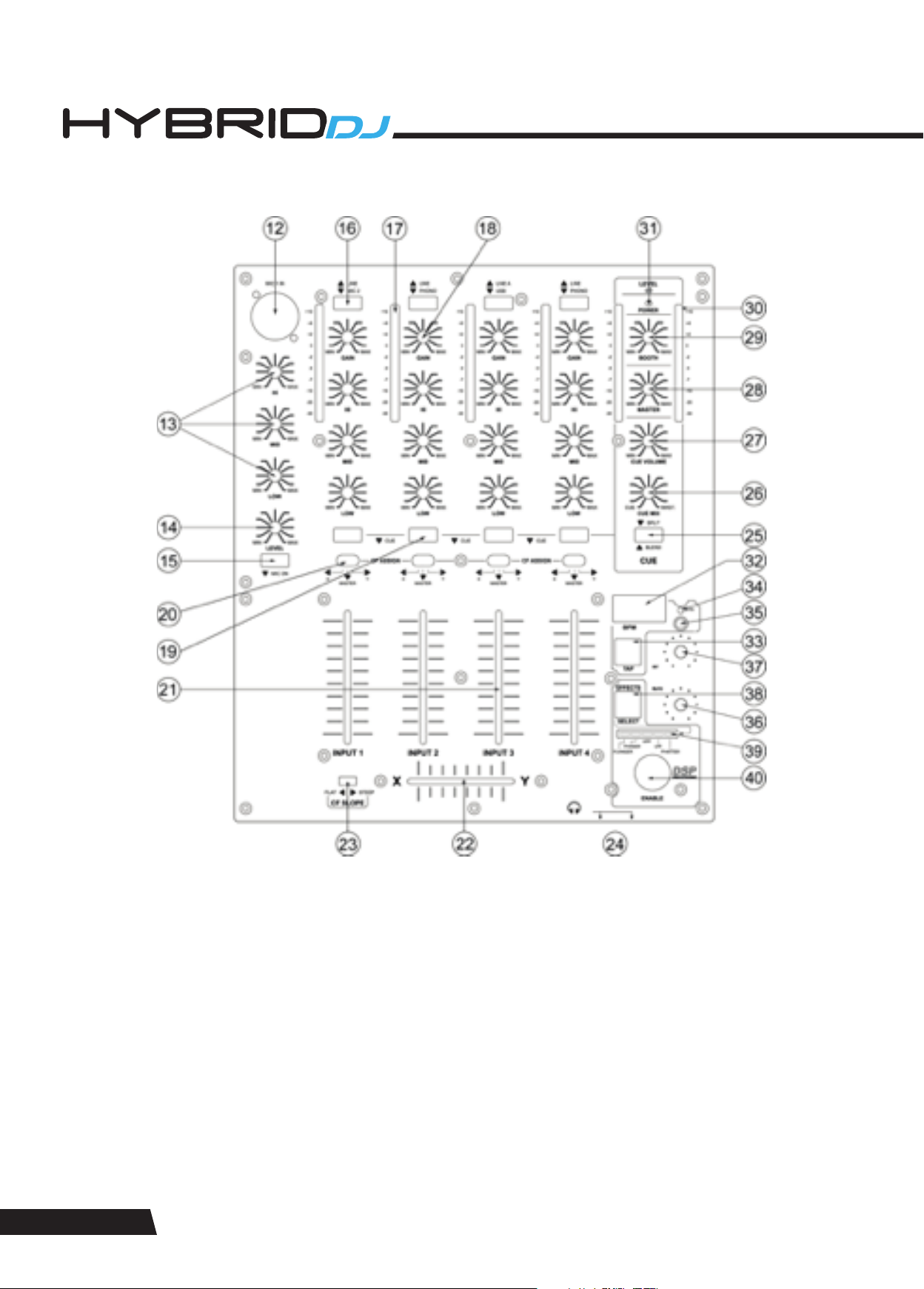
20. Crossfader assignment switch. Allows to route the respective channel either to X (left crossfader side) or to Y (right crossfader
side) or directly to the master.
21. Channel fader for input channels. A high-grade dual rail 60mm fader determines the volume of the respective channel.
22. Crossfader. A high-grade dual rail 45mm fader determines the mix ratio between the stereo signals routed to X (assigned to the
left crossfader side) and Y (assigned to the right crossfader side). If no signals are assigned by means of the switches (19), the
crossfader is disabled.
23. Crossfader Curve switch. Allows the transition characteristic of the crossfader between the X and Y signal to be switches between
smooth a flat and steep mixing curve.
24. Headphones output. A ¼” TRS connector to connect a headphone. Turn the CUE level (26) down before plugging in headphones.
25. CUE Mode switch. This control offers two pre-listening modes: (A) Split. In this mode, the master signal appears on one earcup of
the headphones, the CUE signal on the other earcup. (B) Blend. In this mode, main and CUE signal are mixed with adjustable
ration by means of control (25). A LED indicates the pressed position.
26. CUE Mix control. If the CUE mode (24) is set to “BLEND”, the headphone signal can be a mix of the main output and the input(s)
assigned to the CUE bus by means of switches (25). This control determines the mix ration between the main and the CUE signal.
27. CUE volume. Determines the signal volume at the headphone output (23). Always set this control to minimum before putting on
headphones, as sudden high-volume impact may damage your ears. See further health advice below.
28. Output level control. Determines the main output level present at outputs (3) and (4).
29. Booth level control. Determines the booth output level present at output (5).
30. Output level meter. Displays the output level at outputs (3) and (4).
31. Power LED. Indicates the on/off status of unit.
EFFECTS SECTION
32. BPM display. Displays the BPM value of the current music signal played through the main output. The BPM display will show “ - - -
. – “ if the music signal has not enough sensible rhythmic content to automatically determine a BPM value. In such case, wait unit
the enough rhythmic content becomes available, or use the manual tap mode by means of the TAP button (33).
33. TAP button. This button allows to determine a BPM value manually. If the music signal has a rhythmic structure too complex or
not determined by percussive sounds, the automatic BPM counter may not be able to derive a sensible result and will display “
- - - . – “ on the display (32). In this case, you can use the Tap button to tap along the music; after 4 taps, the display (32) will show
the average speed of your tapping in BPM. The longer you tap, the more precise the result will get due to build-in averaging. Once
you stop tapping, the last result remains displayed on (32). If you wish to switch back to automatic mode, just press the Tap button
once. Whether in automatic or manual mode, the tap button will flash with the speed of the displayed value in (32).
34. SYNC LED. This LED indicates whether the time base of the chosen effect (where applicable) is in synchronization with the BPM
value displayed in (32). In this case, the LED is fully lit. If the time base of the chosen effect (where applicable) is based on the
value shown in the display (32) but has been modified by means of the RATE control (36), the LED will flash. If the time base of the
chosen effect (where applicable) is not related to the displayed value in (32), but based on a default 120 BPM time base, the LED
will be off. The default status (upon start-up) is off (time base = 120 BPM).
35. SYNC Switch. This switch allows to synchronize the time base of the effect (where applicable) with the BPM value displayed in
(32), independent of whether such value has been derived automatically or by manual tapping with (33). After start-up, the unit is
in not-synchronized mode, which means all effect time bases (where applicable) are set to a default of 120 BPM. Pressing the
SYNC switch once will synchronize the effects’ time base (where applicable) to the displayed BPM in (32), and the SYNC LED (34)
will be lit. Pressing the SYNC switch again will switch back the effect time base to 120BPM. In case the synchronization is active
and the SYNC LED is lit, the user may vary the time base of the effect by turning the RATE control (36), where the displayed BPM-t
ime base will be prorated accordingly. This deviation from the synchronized time base will be visible by the SYNC LED flashing.
Pressing the SYNC switch once when the SYNC LED is flashing will reset the time base to the display BOM value in (32).
36. RATE/(FREQUENCY) control. Allows to change the speed rate with or without BPM synchronization, or the effect frequency
(depending on the chosen effect, see below).
37. INTENSITY/(MIX) control. Allow to set an intensity parameter for the effect, or (depending in the chosen effect, see below) the
setting of the dry/wet mix ration between effect and original signal.
38. Effect selector switch. This switch allows to consecutively step through the five provided effects. The selected effect is indicated by
the LEDs in the selection bargraph (39). The effects available are listed at the end of this chapter.
39. Effects selection bargraph. Indicates which effect is selected. Please note that once the chose effect is changed, the last setting
of the Rate/(Frequency) control (36) is stored and will be recalled whenever returning to this effect; however, the Intensity/(Mix)
parameter is a global setting and will not be stored with the effects.
40. Effects ON/OFF switch. Activates the effect which is chosen by (38). Once the effect is active, this switch is backlit.